Abstract— This paper presents a new approach to upgrade and extend the reach of the current passive optical network (PON) by using wavelength division multiplexing (WDM) in the standardized optical grid of gigabit PON (In-band WDM PON overlay). The aim is to increase the number of optical distribution networks (ODNs) fed by a single fiber while preserving the users bandwidth. In this approach four downstream (DS) wavelength signals are transmitted from an optical line terminal (OLT) to four different ODNs using the standard DS PON spectrum ranging from 1480 to 1500 nm. The upstream (US) signals from the four different ODNs are also wavelength multiplexed within the standardized US PON spectrum ranging from 1270 to 1330 nm. Experimental proofs of concept are presented in a 20 km PON serving 32 ONTs and in a 58 km extended PON in order to demonstrate the feasibility of this proposal.
Index Terms—PON Overlay, PON Stacking, GPON, GEPON CWDM.
I. INTRODUCTION
Current passive optical networks (PON), such as gigabit passive optical network (GPON) and
gigabit Ethernet passive optical network (GEPON), are recognized as market leaders in optical access
deployments. The upgrade or the evolution of these networks has been proposed and analyzed in the
literature [1]-[4].
The trivial PON evolution is to increase the transmission bit ratio to 10 Gb/s or to use dense
wavelength division multiplexing (DWDM) [4]. However there are also some ITU-T studies to
implement the concept of a coarse wavelength division multiplexing (CWDM) PON overlay or PON
stacking, which are extensions of standard PON equipment based on several independent colored
PON systems over a single optical distribution network (ODN) infrastructure and that enable a
wavelength level unbundling [5]-[6].
Previous works proposed a CWDM PON overlay network to increase the number of ODNs
powered by a single fiber [7]-[9]. In [7] a CWDM PON overlay was proposed to increase fourfold the
downstream (DS) network capacity, while maintaining the ability to upstream (US) by 1.25 Gb/s.
According to [7] the optical line terminal (OLT) is replaced keeping the optical network terminals
Upgrading and Extending PON by Using
In-Band WDM Overlay
Rivael Strobel Penze(1), Joao Batista Rosolem(1), Renato Baldini Filho(2)
(1)CPqD – Research and Development Center in Telecommunications, Campinas, SP, Brazil E.mail [email protected], [email protected]
(2)
to the standardized PON channel of 1490 nm are used as downstream channels to the ONTs. The
same authors also analyze this topology in [8] applied for an extended reach PON. In [9] it is
presented the overlay of five gigabit signals operating between 1531nm to 1611nm over a working
G-PON.
Nowadays, these DS CWDM wavelengths are incompatible with the optical bandwidth of the
current ONT transceivers which work in the range from 1480 nm to 1500 nm (S band) according
ITU-T G.984.2 [10]. ITU-Therefore the ONITU-T transceiver filter must be re-designed. However, ONITU-T
transceivers are currently in mass production which makes difficult to apply this proposal in the
current PON architecture.
This paper presents a new approach to upgrade the current PON by using WDM in the standardized
PON optical grid. This approach is named In-band PON overlay. Four channels chosen in S band
(1482, 1486, 1492 and 1496 nm) are transmitted from the OLT to four different ODNs. The upstream
signals (1270, 1290, 1310 and 1330 nm) from the four different ODNs are also multiplexed within the
standardized OLT O band receiver spectrum. This procedure allows the network to be expanded
preserving the same standardized PON spectrum. In addition, the user bandwidths are kept unchanged
despite of the network upgrading. The network topology is described and an experimental proof of
concept is presented in order to demonstrate the feasibility of this proposal. In addition, we show the
feasibility to increase the reach of the proposed network by using SOA’s based extender. It is also
presented the experimental results of the extended network operation for four downstream channels
centered in 1490 nm and four upstream channels centered in 1300 nm, using downstream and
upstream transmission rate of 2.5 Gb/s in a 20 km PON serving 32 ONTs and in a 58 km extended
PON.
II. PONOVERLAYARCHITECTURES
A. Previous CWDM PON overlay grids
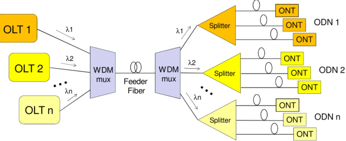
The traditional PON overlay architecture is shown in Fig. 1. Several PONs use different CWDM
wavelengths for DS and US signals [11]. Therefore, the total capacity of the feeder fiber is increased,
making this architecture very attractive to extend the reach of feeder fiber. Since, the fiber plant cost
increases with the reach, sharing various ODNs in the same feeder is an effective way for network
OLT 1
OLT 2
OLT n
ONT ONT ONT ODN 1 ONT ONT ONT ODN 2 ONT ONT ONT ODN n Feeder Fiber Splitter WDM mux WDM mux Splitter Splitter λ1 λ2 λn λ1 λ2 λnFig. 1. Generic diagram for a CWDM PON overlay.
Fig. 2 shows the CWDM optical grid [12] available for PON overlay operation. The spectra
reserved for GPON systems [10], XGPON [13] and Video Overlay [14] systems are also shown in
this figure. These systems will coexist in the same current implanted optical network establishing
probably the first standardized PON overlay.
Notice that in the CWDM PON overlay demonstration described in [6] the DS wavelengths are
1430 nm, 1450 nm, 1470 nm and 1490 nm (See Fig. 2). In the demonstration described in [8] the DS
wavelengths are 1531 nm, 1551 nm, 1571 nm, 1591 and 1611 nm. None of these demonstrations
includes grid for US channels.
1 3 5 1 1 3 7 1 1 3 9 1 1 4 11 1 2 7 1 1 2 9 1 1 3 11 1 3 3 1 1 5 11 1 5 3 1 1 5 5 1 1 5 7 1 1 4 3 1 1 4 5 1 1 4 7 1 1 4 9 1 1 5 9 1 1 6
11 λ(nm) CWDM Grid
10G-PON US G-PON US
This work US This work DS
10G-PON DS G-PON DS Video Overlay DS proposed in [7] DS proposed in [9]
Fig. 2. Available spectrum grid for a WDM PON overlay.
B. In-band WDM PON overlay architecture
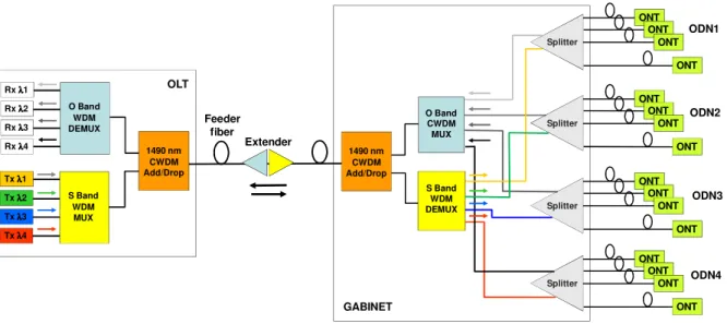
The proposed in-band WDM PON overlay architecture is shown in Fig. 3. The basic concept is to
increase the number of ODNs fed by just one single fiber. This PON architecture uses four S band
wavelengths transmitted from an OLT to four different ODNs. The experiment makes use of selected
commercial distributed feedback (DFB) lasers that operated in the standardized PON DS spectrum
band (1480 nm to 1500 nm). The downstream wavelengths are 1482, 1487, 1492 and 1497 nm
(Fig.2). The 5 nm spacing between the wavelengths is allowed to match with the grid of selected
Tx λλλλ1 Tx λλλλ2 Tx λλλλ3 Tx λλλλ4
OLT
ODN3 Feeder
fiber
Rx λλλλ1 Rx λλλλ2 Rx λλλλ3
Rxλλλλ4 1490 nm CWDM Add/Drop
S Band WDM DEMUX O Band CWDM MUX 1490 nm
CWDM Add/Drop
S Band WDM MUX O Band
WDM DEMUX
Splitter
ONT ONT
ONT
ONT
Splitter
ONT ONT
ONT
ONT
Splitter
ONT ONT
ONT
ONT Splitter
ONT ONT
ONT
ONT
ODN4 ODN2 ODN1
GABINET Extender
Fig. 3. Proposed in band WDM PON overlay architecture using standardized transceiver’s bands.
In the OLT the four S band channels are multiplexed in the feeder fiber by means of one S band
mux and one 1x2 1490 nm add/drop CWDM filter. The same add/drop filter connects the upstream
channels to one 1x4 O band CWDM demultiplexer (demux) that is followed by the optical OLT
receivers.
In the far end of the feeder fiber, the downstream channels and the upstream channels are again
routed by other 1x2 1490 nm add/drop CWDM filter. The downstream channels are inserted into four
ODNs by means of one S band demux. Notice that each ODN contains one 2xN splitter.
All ONTs transmitters, belonging to a given ODN, send the upstream signals using a specific
CWDM channel. The wavelengths for the four OLTs are in the range from 1270 nm to 1330 nm
(Fig.2). These wavelengths have been chosen by the following reasons: they are within the
standardized OLT receiver spectrum; they are CWDM channels standardized by ITU-T [12]; they
have already been used in deployed PONs [5], and also they allow PON extension by using
semiconductor optical amplifiers (SOAs) with spectrum gain matched to these wavelengths [15].
The upstream channels, after passing through the splitters, are multiplexed by means of one 1x4 O
band CWDM mux and they are connected in the feeder fiber by the 1x2 1490 nm add/drop CWDM
filter. The 1x4 O band CWDM mux may be replaced by one 1x4 splitter if its insertion loss can be
absorbed by the link power budget.
In the OLT, other 1x2 1490 nm add/drop CWDM filter directs the upstream signals to a 1x4 O band
CWDM demux and, finally, to the optical receivers.
A PON extender based on the use of SOAs has also been utilized before the ODNs. This application
III. PROOFSOFCONCEPT
A. Network Upgrading
The in-band WDM PON overlay architecture shown in Fig. 3 was firstly implemented without a
PON extender. The feeder fiber length was 20 km composed by a standard single mode fiber. The
OLT and the ONT channels performance were evaluated in terms of bit error rate (BER), using
transmission bit rate of 2.5 Gb/s, and a pseudo-random binary sequence (PRBS) with length equal to
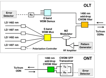
223-1. Fig. 4 shows the OLT and OLT prototype diagrams used only to demonstrate our proposal. In
the OLT, four S band DFB lasers operating in continuous wave (CW) power inject their signals in one
Mach-Zender (MZ) LiNbO3 modulator by means of the S band mux. Polarization controllers are used
to adjust the right polarization of the signals in the modulator input. The electrical signal of a pattern
generator is amplified before injected in the MZ modulator.
O band WDM Demux Rx
Error Detector
LD 1482 nm
Polarization Controller
S band WDM Mux
OLT
LD 1487 nm
LD 1492 nm
LD 1497 nm
RF Amplifier
MZ Modulator
Pattern Generator
1490 nm add/drop CWDM filter
To/from ODNs
1490 nm add/drop CWDM filter
CWDM SFP
Transceiver ONT
Error Detector Rx
Tx To/from
ODN
Fig. 4. Details of the OLT and OLT prototype diagrams.
Each ONT uses a commercial CWDM small form pluggable (SFP) transceivers and one 1x2 1490
nm add/drop CWDM filter to connect the downstream channel in the receiver and the upstream
channel in the 2x32 splitter arm. The ONT and OLT receivers use APD (Avalanche Photo Diode)
detectors with -31 dBm average sensitivity (ONT) and -33.5 dBm average sensitivity (OLT). The
average optical power transmitted by each laser in S band is 1.3 dBm and 0 dBm for O band CWDM.
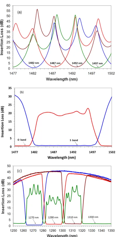
Fig. 5 shows the total insertion loss/insulation of (a) S band demultiplexer, (b) 1490 add/drop
CWDM and (c) O band demultiplexer. The maximum insertion losses for multi/demultiplexers are: S
band WDM mux/demux = 1.6 dB, O band WDM mux/demux = 1.8 dB, 1490 nm add/drop CWDM
filter = 0.7 dB and the 2x32 Splitter = 15.8 dB. The fiber attenuation at O band ranges from 0.39
dB/km dB at 1270 nm to 0.31 dB/km at 1330 nm. At S band, the average fiber attenuation is 0.22
(a)
0 5 10 15 20 25 30 35
1477 1482 1487 1492 1497 1502
In
se
rt
io
n
L
o
ss
(
d
B
)
Wavelength (nm) (b)
S band O band
Fig. 5. Mux loss/insulation for (a) S band, (b) 1490 add/drop CWDM and (c) O band.
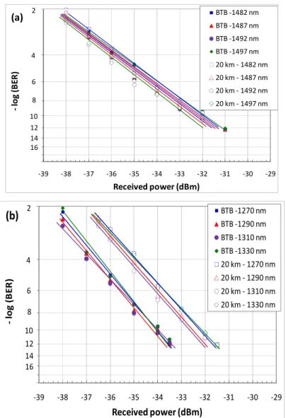
Fig. 6(a) shows the BER performance evaluation for S band channels and Fig. 6(b) shows it to O
band channels measured, respectively, in the ONT and in OLT with and without fiber (BTB). The
power penalty is null at BER = 1x10-12 for downstream channels and it is around 2 dB for upstream
channels. The power penalty for upstream channels is entirely absorbed by the system optical budged.
The margin for the downstream and upstream channels is 2 dB at BER = 1x10-12. Fig.7 shows the
2
20
-39 -38 -37 -36 -35 -34 -33 -32 -31 -30 -29
-lo
g
(
B
E
R
)
Received power (dBm)
BTB -1482 nm BTB -1487 nm BTB -1492 nm BTB -1497 nm 20 km - 1482 nm 20 km - 1487 nm 20 km - 1492 nm 20 km - 1497 nm 4
6
8
10 12 2
14 16 (a)
2
20
-39 -38 -37 -36 -35 -34 -33 -32 -31 -30 -29
-lo
g
(
B
E
R
)
Received power (dBm)
BTB -1270 nm BTB -1290 nm BTB -1310 nm BTB -1330 nm 20 km - 1270 nm 20 km - 1290 nm 20 km - 1310 nm 20 km - 1330 nm 4
6
8
10 12 2
14 16
(b)
Fig. 6. The BER performance evaluation for (a) S band downstream channels measured in ONT and (b) O band upstream
channels measured in OLT.
B. Network Upgrading and Extending
In order to verify the reach increase of in-band WDM PON overlay architecture, a PON extender
based in SOAs is used. The bi-directional SOAs circuit is presented in Fig. 8. It is utilized a
1310/1490 nm fuser coupler to connect the input and output of two commercial SOAs, one for 1310
nm spectral band and other for 1490 nm spectral band. Fig. 3 shows the extender position in the fiber
link, i.e., after 50 km from the OLT. Following the PON extender it is deployed 8 km fiber. These two
fiber links have same attenuation as for the 20 km link previously described.
PON Extender 1.3/1.49 µm
Mux
O Band S Band
50 km 8 km
A
1.3/1.49 µm Mux
Fig. 8. Details of the bidirectional PON extender.
Typical characteristics of the SOAs are: loss signal gain greater than 15 dB in 1490 nm and in 1310
nm, operation current equal to 200 mA, and polarization sensitivity better than 1.5 dB. An optical
attenuator is used in the input of the 1490 nm SOA to avoid BER degradation caused by cross gain
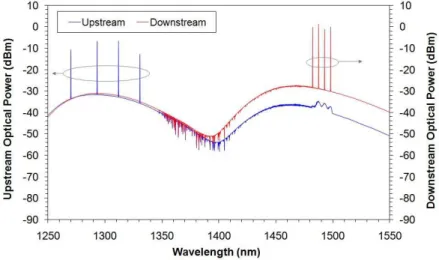
modulation in nonlinear regime. Fig. 9 shows the spectrum of the PON extender outputs according to
its position presented in Fig. 1. Notice that the gain bandwidth is 15 nm in S band and it is 60 nm in O
band.
In the position where the extender is utilized the average input power per channel for S band
channels is approximately -13.5 dBm (-23.5 dBm after the attenuator) and the gains are 13.5 dB (1482
nm), 13.8 dB (1487 nm), 13.1 dB (1492 nm) and 12.8 dB (1497 nm). The gains for O band channels
are (average input power per channel ≈ -24 dBm): 11.9 dB (1270 nm), 17.4 dB (1290 nm), 16.8 dB (1310 nm) and 14.1 dB (1330 nm).
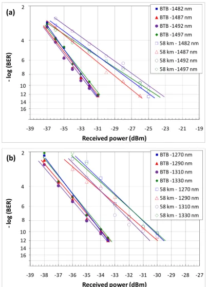
Fig.10(a) shows the BER performance evaluation for S band and Fig. 10(b) shows the BER
performance evaluation for O band channels measured in the ONT and in OLT, respectively,
compared to BTB measurements. The power penalty is around 7 dB at BER = 1x10-12 for S band
channels and it is around 4 dB for O band. These penalties are attributed to the signal-to-ASE
(Amplified Spontaneous Emission) beat noise process in the optical receivers.
Further experiments were conducted in order to test the ONT receiver performance due to the
possible thermal wavelength variation of S band lasers. Since the S band multiplexer/demultiplexer
transmission band is not flat (see Fig. 5(a)), the spectral variation of S band lasers can degrade the
BER in the ONTs. Figure 11 shows the BER and received power performance of one S band channel
(1492 nm) measured in an ONT receiver when the wavelength of the laser is thermally changed by +/-
2.5 nm. It is observed that the BER performance is not changed for +/-0.75 nm because the optical
received power does not change in this range. This specific measurement point was chosen to
demonstrate the problems concerned with the channel bandwidth.
2
20
-39 -37 -35 -33 -31 -29 -27 -25 -23 -21 -19
-lo
g
(
B
E
R
)
Received power (dBm)
BTB -1482 nm
BTB -1487 nm
BTB -1492 nm
BTB -1497 nm
58 km - 1482 nm
58 km -1487 nm 58 km -1492 nm
58 km -1497 nm 4
6
8
10 12 2
14 16
(a)
2
20
-39 -38 -37 -36 -35 -34 -33 -32 -31 -30 -29 -28 -27
-lo
g
(
B
E
R
)
Received power (dBm)
BTB -1270 nm
BTB -1290 nm
BTB -1310 nm
BTB -1330 nm 58 km - 1270 nm
58 km - 1290 nm
58 km - 1310 nm
58 km - 1330 nm 4
6
8
10 12 2
14 16
(b)
Fig. 10. The extended PON BER performance evaluation for (a) S band downstream channels measured in ONT and (b)
O band upstream channels measured in OLT.
According this evaluation the maximum temperature operation for the S band lasers in this
wavelengths by 0.075 nm/ºC. The S band mux and demux using dielectric filters technology could
extend the operational temperature range since they have flat bandwidth, however they are not
available in S band currently with 5 nm wavelength spacing.
1,E-12 1,E-11 1,E-10 1,E-09 1,E-08 1,E-07 1,E-06 1,E-05 1,E-04 1,E-03
-45 -40 -35 -30 -25 -20 -15 -10 -5 0
-3 -2 -1 0 1 2 3
B
E
R
R
e
ce
iv
e
d
p
o
w
e
r
(d
B
m
)
Δλλλλ(nm)
Received power 1492 nm
BER 1492 nm
Fig.11. BER and received power performance of one S band channel (1492 nm) measured in ONT receiver when the laser
wavelength is changed by +/- 2.5 nm.
IV. CONCLUSION
This paper has presented a new proposal to upgrade and to extend the currently PON by using
WDM in the standard GPON or EPON optical grid. The aim is to increase the number of optical
distribution networks powered by a single fiber while preserving the users’ bandwidth. Four
wavelengths channels are transmitted from the OLT to four different ODNs using the standardized
ONT receiver ranging from 1480 to 1500 nm. The upstream channels from the four different ODNs
are also wavelength multiplexed using the standardized OLT receiver band spectrum ranging from
1270 to 1330 nm. The network topology has been described and an experimental proof of concept has
been presented. The good bit-error-rate performance presented by the proposal has shown its
feasibility.
REFERENCES
[1] F. An, K. S. Kim, D. Gutierrez, S. Yam, E. Hu, K. Shrikhande, and L. G. Kazovski, “SUCCESS: a next-generation hybrid WDM/TDM optical access network architecture”, J. Lightwave Technology, Vol. 22, No 11, pp.2557–2569, November 2004.
[2] K. M. Choi, S. M. Lee, M. H. Kim, and C. H. Lee, “An Efficient Evolution Method from TDM-PON to Next-Generation PON”, IEEE Photonics Technology Letters, Vol. 19, No. 9, pp. 647-649, May 2007.
[3] S. Ahsan, M. S. Lee, S. H. S. Newaz, and S. Asif, “Migration to the Next Generation Optical Access Networks Using Hybrid WDM/TDM-PON”, Journal of Networks, Vol. 6, No. 1, pp.18-25, January 2011.
[4] F. J. Effenberger, J. Kani, and Y. Maeda, “Standardization Trends and Prospective Views on the Next Generation of Broadband Optical Access Systems”, IEEE Journal on Selected Areas In Communications, Vol. 28, No. 6, August 2010.
[5] T. Pfeiffer, “Enhancing PON capabilities using the wavelength domain”, Join ITU-T/IEEE Workshop on Next Generation Optical Access Systems, Geneva, Switzerland, 2008.
[7] M. Bouda, P. Palacharla, Y. Akasaka, A.Umnov, C. Tian, and T. Naito, "Cost-Effective Optical Access Upgrades Using Wavelength Shared Hybrid Passive Optical Network Architecture", in National Fiber Optic Engineers Conference, OSA Technical Digest Series (CD) (Optical Society of America, 2007, paper NThD5.
[8] M. Bouda, P. Palacharla, Y. Akasaka, A.Umnov, and T. Naito, "Extended-Reach Wavelength-Shared Hybrid PON", in Optical Fiber Communication Conference and Exposition and The National Fiber Optic Engineers Conference, Technical Digest (CD) (Optical Society of America, 2008, paper NThD5.
[9] K. McCammon and S. Wong “Experimental Validation of an Access Evolution Strategy: Smooth FTTP Service Migration Path”, in National Fiber Optic Engineers Conference, OSA Technical Digest Series (CD) (Optical Society of America, 2007, paper NThD5.
[10]G.984.2, “Gigabit-capable Passive Optical Networks (GPON): Physical Media Dependent (PMD) layer specification”, ITU-T, 2003.
[11]J. Kani, “Enabling Technologies for Future Scalable and Flexible WDM-PON and WDM/TDM-PON Systems”, IEEE Journal of Selected Topics in Quantum Electronics, Vol. 16, No. 5, pp.1290-1297, September/October 2010.
[12]G.694.2, “Spectral grids for WDM applications: CWDM frequency grid”, ITU-T, 2002.
[13]G.987.1, “10-Gigabit-capable passive optical networks (XG-PON): General requirements”, 2010.