_____________________________
*) Corresponding author: [email protected]
doi: 10.2298/SOS0902199D
UDK 621.785:57.012.3
Microstructure and Properties of Boronizing Layer of Fe-based
Powder Metallurgy Compacts Prepared by Boronizing and
Sintering Simultaneously
X. Dong, J. Hu, Z. Huang, H. Wang, R. Gao, Z. Guo
*)The Key Lab of Automobile Materials, Ministry of Education, College of Materials
Science and Engineering, Jilin University, Changchun, 130025, China
Abstract:
In this study, the boronized layers were formed on the surfaces of specimens with a composition of Fe-2 wt. % Cu-0.4 wt. % C by sintering and boronizing simultaneously, using a pack boronizing method. The processes were performed in the temperature range of 1050 - 1150 oC at a holding time of 4 hours in 97 % N2 and 3 % H2 atmosphere. Scanning electron
microscopy examinations showed that the boronized layers formed on the surface of boronized and sintered specimens have a denticular morphology. The thicknesses of the
boronized layers varied from 63 to 208 μm depending on the processing temperature. The
structures of the boronized layers were Fe2B and FeB confirmed by X-ray diffraction
analysis. The microhardness values of boronized layers ranged from 1360 to 2066 HV0.3
much higher than that of substrate hardness which was about 186 HV0.3. Wear testing results
showed that the wear resistance of the boronized and sintered specimens was significantly improved, resulting from increased surface microhardness.
Keywords: Powder metallurgy; Pack boronizing; Microstructure; Microhardness; Wear.
Introduction
Manufacturing of many mechanical components [1-3] by powder metallurgy (P/M) technology has been frequently used in manufacturing industry owing to their low energy consumption, high materials utilization and low production cost resulting from the near net shape process [4-6]. Therefore, some P/M structural parts with high sintered density as well as high wear resistance have been widely used in automotive systems, such as cam lobes, gears and valve seats etc. [3]. The surface hardening was usually carried out for these components to obtain a harder layer on surfaces and tough core in the center, which exhibited both high wear resistance and strength. In the past few years, surface hardening processes such as gas nitriding [1, 7, 8], plasma nitriding [5, 9], glow-discharge treatment [10], nitriding and nitrocarburizing [11], as well as surface carburizing [12, 13] treatments have been widely used for surface hardening treatments of P/M parts.
alloys, titanium alloys, and sintered carbides [14, 15]. Generally, the process temperature of thermal diffusion treatments of boronizing compounds should be between 973 and 1273 K. This process can be performed in solid, liquid or gaseous medium. The most frequently utilized method is pack boronizing which is a process similar to pack carburizing process. Especially, powder-pack boronizing has the advantage of simplicity and cost-effectiveness in comparison with other boronizing processes [16-19]. Boron atoms, owing to their relatively small size and high mobility at process temperature can diffuse into ferrous metals, resulting in the formation of both single Fe2B and FeB-based polyphases coatings which is mainly used
to improve wear resistance of the components for tribological applications. The thickness and proportion of each boride depend on chemical composition of workpiece, boronizing medium, process temperature and duration of treatment [16, 20-22].
In the present study, boronizing of P/M parts can be referred to as a one-step process in which boronizing and sintering are fulfilled simultaneously. Its obvious merit is to simplify the traditional boronizing process and decrease production costs. The purpose of this paper is to provide an available boronizing-sintering process for the production of P/M materials with boride in their surface. It is also expected that this study could help to develop the fabrication of special P/M materials with good properties of a surface layer containing boride.
2. Experimental procedures
2.1 Materials and sintering process
The water atomized iron powder (Höganäs AHC100.29), together with 2 wt. % copper and 0.4 wt. % natural graphite with purity higher than 99 %, were used to fabricate compacts. The average diameters of different particles for iron, copper and graphite were 45-125 μm, 37 μm and 60 μm, respectively. Mineral oil (0.3 ml/kg) and zinc stearate (5 g/kg) were added to the mixture as lubricant. After being blended with a blender running at a rate of 33 rpm for 60 min, the powder mixture was uniaxially cold pressed to a green density of 7.0 g/cm3. The size of the compacts was Ø 13 mm×10.6 mm. The compacts were enveloped by boronizing medium which contains 5 wt. % B4C as donor, 5 wt. % KBF4 as an activity and
90 wt. % SiC as diluent. Subsequently, they were packed in a boronizing box made of special steel. The box was then placed into an electrical resistance furnace for boronizing. The compact specimens were boronized at different temperatures (1050, 1100, 1120 and 1150 oC) for 4 hours in a 90 % N2 - 3 % H2 atmosphere. The specimens were taken out from the box by
removing the used boronizing mixture when the box was gradually cooled to room temperature.
2.2 Characterization of boronized specimens
After the surfaces of the boronized specimens were ground, polished and etched with a 4% Nital solution, their microstructures were observed by SEM (Model JSM-5310, Japan). The average thickness of the boronized layers was measured in the microscope.
The presence of borides formed on specimen surfaces was checked by a Rigaku X-ray diffractometer (D/Max 2500PC) with a Cu Kα radiation source of a wavelength of 1.541 Å over a 2θ range from 20 o to 90 o.
The Vickers microhardness measurements were carried out from the surface to the substrate along the cross-section using a HXD-1000 microhardness tester with a load of 300 g and indentation time of 15 s. The final values quoted for the microhardness were the averages of 10 measurements.
diameter and 10 mm in height were machined from the boronized specimens and the only sintered specimens for comparison. Specimen surfaces were thoroughly degreased by acetone and dried before wear testing. The tests were carried out with different applied loads (40, 70, 100, 130 and 160 N) at a sliding speed of 0.785m/s. Specimens were weighed on an electrical balance with an accuracy of 0.1 mg before and after wear testing. The weight losses calculated by worn volume before and after wear testing were given by the averages of three specimens after sliding distance of 376.8 m. The 70 mm-diameter disc made of high carbon chromium steel was hardened to a hardness of 57 HRC, and the bearing surface of the disc was grounded to a constant surface roughness of ~0.4 μm Ra. The worn surfaces of the wear pins were examined by SEM.
3. Results and Discussions
3.1 X-ray diffraction analysis
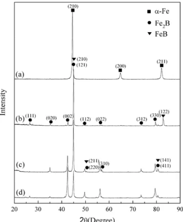
Fig. 1 shows the XRD patterns for the boronized specimens at different temperatures for 4 hrs and un-boronized specimens sintered at 1120 oC for 4 hrs. It can be seen that the surface of the un-boronized specimen is mainly -Fe shown in Fig. 1(a). After boronizing treatment at 1050, 1120, 1150 oC for 4 hrs, the XRD patterns as shown in Fig. 1(b), (c), (d), reveal that the boronized layers mainly consist of Fe2B, and only a small amount of FeB was
detected.
Furthermore, the intensity of the Fe2B (002), (022) and (330) peaks become more
intensive as boronizing temperature increases, indicating that these Fe2B orientation were
becoming dominant for higher boronizing temperature.
3.2 Microstructures
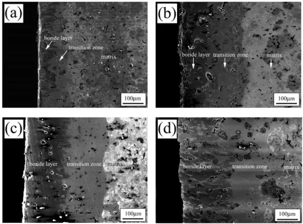
The cross-sectional microstructures of the boronized layer for different specimens are shown in Fig. 2. It can be seen that the surfaces of the boronized specimens are composed of three distinct regions, i.e.: (i) a surface layer, primarily consisting of Fe2B and FeB phases; (ii)
a transition zone, being rich in boron and (iii) matrix, which is not affected by boronizing process.
Fig. 2 The microstructure in a cross-section of a boronized layer of specimens boronized at: (a) 1050 oC, (b) 1100 oC (c) 1120 oC, (d) 1150 oC for 4 hrs, respectively.
The prominent phase formed in the boronized layer is Fe2B while a small amount of
FeB is detected by XRD analysis (Fig.1). As the boronized temperature increases, the boronized layer becomes thicker.
The thicknesses of the boronized layer corresponding to the sintering temperature are listed in Tab. I.
Tab. I Case depth of boronized specimens at different temperature for 4 hrs.
Temperature (oC) The depth of boride layer
(μm)
3.3 Microhardness and wear behavior
3.3.1 Microhardness
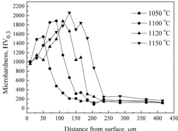
The microhardness of the boronized layer, transition zone and matrix were measured along the cross-section of specimens, as shown in Fig. 4. The microhardness in the outer part of the boronized layer is relatively lower resulting from the crystallographic disorder and friability, which is in agreement with the results in Ref. [23]. It can be seen that the microhardness is higher in the subsurface of boronized layer. And the microhardness values of specimens boronized at different temperatures are in the range of 1487-1545 (1050 oC), 1354-1887 (1100 oC), 1331-1882 (1120 oC) and 1360-2066 (1150 oC) HV0.3, respectively. It
can be found from Fig. 4 that the microhardness values of all these boronized layers are much higher than that of the substrate, i.e. 186 HV0.3. The transitional regions have an intermediate
microhardness of about 855 HV0.3, which is also higher than that of the substrate.
Fig. 3 Microhardness profiles in cross section of boronized layers fromed on the surface of specimens boronized at different temperature for 4 hrs.
Then, the microhardness gradually decreases along the cross-section until reaching the substrate at ~250 μm. The enhancement in the microhardness on the surface is due to the presence of harder phases Fe2B and FeB (see Fig. 2). It can be seen from Fig. 3 that the
microhardness values of the boronized layer is related to the temperature which is in accordance with the tendency that the thickness of the layer increases with increasing temperature as shown in Fig. 2.
3.3.2 Wear behavior
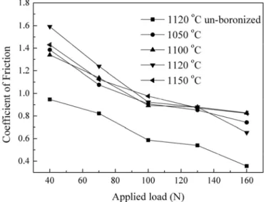
the friction coefficients have a highest value at 40 N and gradually decrease and finally decrease to the lowest level at high load with the loads increases. For the boronized specimens, the changing trend of the friction coefficient with load is similar to that of the as-sintered specimen. It is obvious that the friction coefficient of the boronized specimens is much higher than that of the as-sintered specimens under the same applied load. It is probably due to a large amount of worn debris are produced in the sliding and reached steady-state. The debris compositions may significantly affect the friction behavior, e.g. softer debris usually produces lower friction [24].
Fig. 4 Variation of friction coefficient to loads for the boronized and un-boronized specimens.
Fig. 5 Variation of wear rate to loads for boronized and un-boronized specimens.
conditions, it is obvious that the wear resistance increases with the increase of the surface microhardness and the layer thickness. It can be clearly seen from the inset shown in Fig. 5, at 1050oC, the wear rate increases rapidly as the applied load beyond 100 N, which is ascribed to the thinner boronized layer compared to that boronized at the higher temperatures.
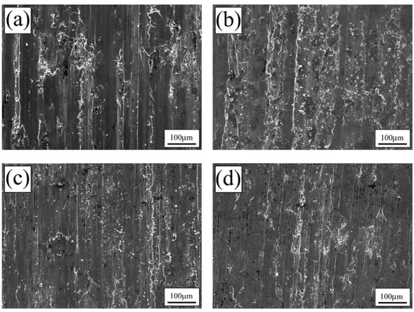
Fig. 6 SEM micrographs of worn surfaces of (a) un-boronized specimen sintered at 1120oC for 4 hrs and boronized specimens at different temperatures: (b) 1050 oC, (c) 1120oC, (d) 1150oC for 4 hrs, respectively.
Fig. 6 shows the micrographs of the worn surfaces of both boronized and un-boronized specimens at the moderate load 100 N. The characterization of the worn surfaces reveals quite different wear behaviour between boronized and un-boronized specimens. From Fig. 6(a), it is seen that abrasive grooves and adhesion wear appear in the worn surface of the un-boronized specimen. The un-boronized specimens are mainly characterized by adhesion, scratch and serious plastic deformation. On the contrast, the boronized specimens are mainly characterized by scuffing and brittle micro-fracture (Fig. 6(b)-(d)). It can be seen that the abrasive wear with a few shallower and narrower grooves are exhibited, and the delaminated debris can be observed.
4. Conclusions
1. It is shown that the powder metallurgy compacts can be boronized in a mixture of SiC-5 wt.% B4C-5 wt.% KBF4 at 1100-1150oC for 4 hrs. The XRD studies reveal that
dominant phase is Fe2B except a little FeB in the boronized layers.
2. The microhardness distribution of the boronized layer presents a gradient change and a hardness range of 1360-2066 HV0.3 is obtained. Experimental results reveal that higher
3. The wear resistance of the boronized specimens is higher than that un-boronized ones under dry sliding conditions.
Acknowledgements
This work is supported by the 'Project 985' Graduate Innovation fund of Jilin University (No. 20080205).
References
1. J. Georgiev, T. Pieczonka, M. Stoytchev, D. Teodosiev, Surf. Coat. Technol. 180-181 (2004) 90.
2. J.S. Park, S.Z. Lee, J.H. Kim, K.N. Lee, Surf. Coat. Technol. 114 (1999) 169. 3. A. Fujiki, Mater. Chem. Phys. 67 (2001) 298.
4. J.A. Wang, H. Danninger, Wear 222(1998) 49.
5. A. Molonari, B. Tesi, T. Bacci, T. Marcu, Surf. Coat. Technol. 140 (2001) 251. 6. K.S. Narasimhan, Mater. Chem. Phys. 67 (2001) 56.
7. J. Kazior, A. Molinari, C. Janczur, T. Pieczonka, Surf. Coat. Technol. 125 (2000) 1. 8. M. Campos, J.M. Torralba, Surf. Coat. Technol. 182 (2004) 351.
9. S.D. de Souza, M. Olzon-Dionysio, E.J. Miola, C.O. Paiva-Santos, Surf. Coat. Technol. 184 (2004) 176.
10. F. Borgioli, E. Galvanetto, T. Bacci, G. Pradelli, Surf. Coat. Technol. 149 (2002) 193.
11. S. Mansoorzadeh, F. Ashrafizadeh, Surf. Coat. Technol. 192 (2005) 231.
12. N. Candela, R. Plaza, M. Rosso, F. Velasco, J.M. Torralba, J. Mater. Proc. Technol. 119 (2001) 7.
13. G. Fillari, T. Murphy and I. Gabrielov, Metal Powder Report 60 (7-8) (2005) 32. 14. A.K. Sinha, ASM Handbook, 4, ASM International, Materials Park, Ohio, USA,
1991, p. 437.
15. R. Chatterjee-Fisher, in: T.S. Sundarshan (Ed.), Surface Modification Technologies, chap. 8, Marcel Dekker Inc, USA, (1989) 567.
16. O. Allaoui, N. Bouaouadja, G. Saindernan, Surf. Coat. Technol. 201 (2006) 3475. 17. G. Celebi, M. Ipek, C. Bindal, A.H. Ucisik, Mater. Forum 39 (2005) 456.
18. O. Ozdemir, M. Usta, C. Bindal, AH.Ucisik, Vacuum 80 (2006) 1391. 19. M. Keddam, S.M. Chentouf, Appl. Surf. Sci. 252 (2005) 393.
20. K. Genel, I. Ozbek, C. Bindal, Mater. Sci. Eng. A 347 (2003) 311. 21. K. Genel, Vacuum 80 (2006) 451.
22. M.A. Be′ jar, E.J. Moreno, J. Mater. Proc. Technol. 173 (2006) 352. 23. G. Palombarini, M. Carbucicchio, J. Mater. Sci. Lett. 6 (1987) 415. 24. J. Qu, P.J. Blau, B.C. Jolly, Wear 263 (1-6) (2007) 719.
Са р а: У ш
ш Fe-2 wt.% Cu-0.4 wt.%C
. ш
1050-1150 4 97% N2 3% H2.
А
ш
. Fe2B
FeB ш ђ . В
1360 2066 HV0.3 ш ш
186 HV0.3.
ш
ш .
К учн р чи: М , , ,