The mechanical response of metallic sandwich beams under foam
projectile impact loading
Abstract
The dynamic response of the clamped sandwich beams was investigated by impacting the beams at mid-span with metal foam projectiles. Effects of applied impulse, face-sheet thick-ness and core thickthick-ness on the impact resistance of sand-wich beams are discussed. Using strain gauge measurement technique, the deformation mechanism of sandwich beams was analyzed in the paper. The results indicate that the structural response is sensitive to the configuration of sand-wich structures. Based on the experiments, corresponding finite element simulations have been undertaken using the LS-DYNA software. A good agreement has been obtained between the numerical and experimental results. The defor-mation and failure modes of sandwich beams under impact loading are presented, i.e. large inelastic deformation, core compression and core shear with interfacial failure. Numer-ical results also show that the velocity-time histories of the mid-span of the front and back sheet of sandwich beams are related to not only core strength but also core thickness. The research results are of worth to the theoretical prediction of the dynamic response of metallic sandwich beam.
Keywords
sandwich beam, impact loading, dynamic response, numeri-cal simulation.
Lin Jinga, Zhihua Wanga,b,∗,
Jianguo Ningb and Longmao Zhaoa
a
Institute of Applied Mechanics and Biomed-ical Engineering, Taiyuan University of Tech-nology, Taiyuan 030024, China
b
State Key Laboratory of Explosion Science and Technology, Beijing Institute of Technol-ogy, Beijing 100081, China
Received 19 Oct 2010; In revised form 6 Dec 2010
∗Author email: wangzh [email protected]
1 INTRODUCTION
structures subjected to quasi-static loading tended to perfection and the dynamic behavior is of current academic and industrial interest. An analytical model is developed by Qiu et al [12] for the deformation response of clamped circular sandwich plates subjected to shock loading. The deformation history is divided into three sequential stages and analytical expressions are derived for the deflection, degree of core compression, and for the overall structural response time. An explicit finite element method is employed to assess the accuracy of the analytical formulas. Results show that the sandwich panel response has only a low sensitivity to the magnitude of the core compressive strength and to the degree of strain hardening in the face-sheets. The corresponding finite element simulations have been undertaken by Xue et al [18] to valid the analytical model. A good agreement has been obtained between the numerical and theoretical results. The importance of both the strength and energy absorbing capacity of the core are highlighted for superior blast resistance. Zhu et al [4, 5] investigated the deformation and failure modes of blast-loaded metallic sandwich panels. The effects on the structural response of face-sheet and core configurations were discussed. Based on the experimental results, corresponding finite element simulations have been undertaken to study the effect of plastic stretching and bending. Based on the experimental and numerical study, Radford [14] investigated experimentally the deformation/failure modes and impact resistance performance of sandwich plates under impact loading. Results show that sandwich plates have a higher impact resistance than monolithic plates of equal mass. Further, a convenient experimental technique was developed to subject structures to high intensity pressure pulses using metal foam projectiles. For completeness, some researches on the deformation/failure modes, [7, 16, 17] loading carrying capacity [2, 16, 17] and plastic energy dissipation [2, 7, 15] of sandwich structures were conducted. However, little attention has been given to the subject of the deformation/failure mechanism and its transition of impulsively loaded sandwich beams on the base of experimental results; and few attempts have been made to investigate the coupling effect between the response stages in the theoretical prediction of sandwich beams with different core thicknesses.
In this paper, the dynamic response of metallic sandwich beams was investigated by using metal foam projectile. The deformation/failure modes of specimen were classified and analyzed, and the deformation mechanism of sandwich beams was discussed by strain gauges records. Based on the experiments, corresponding finite element simulations have been undertaken using the LS-DYNA software.
2 EXPERIMENTAL INVESTIGATION
2.1 Experimental procedure
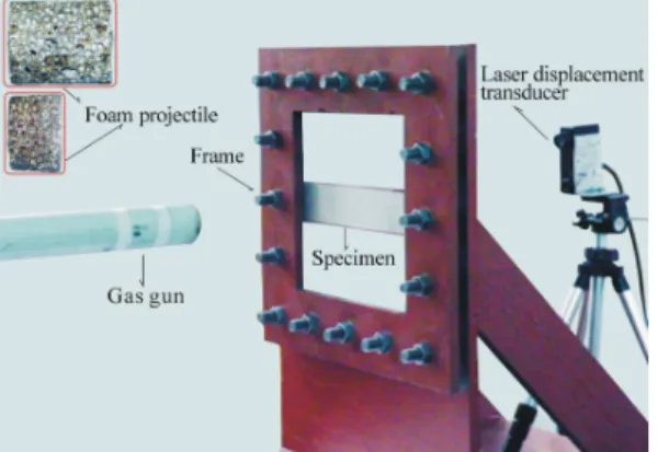
alloy foam, of length l = 45mm, diameter d= 36.5mm and relative density 8.5%. Projectiles were fired from a 37mm diameter bore, 4.5m long gas gun at velocities v0 of 54 to 153m/s, providing a projectile momentum I = mv0 of up to1.59 Ns, where m is the mass of the metallic foam projectile. The overall experimental device includes gas gun, laser displacement transducer, clamping device and data recorder, etc. A sketch of the overall experimental set-up is shown in Fig.2. Strain gauges and high dynamic strain amplifiers were used to obtain the corresponding strain signals of sandwich beams in the deformation process. Single element gauges (BE-120-3AA, zemic.Com, China) with a nominal resistance of 119.9 Ω ± 0.1 and a gauge factor of 2.21 were used to measure the direct strain in the face sheets. Fig.3 shows the location of the gauges on the face sheets.
Figure 1 Geometry and dimension of the specimen.
Figure 2 The sketch of the experimental set-up.
2.2 Experimental results
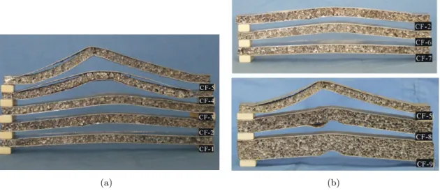
The experimental results are classified into two types, i.e. (1) observed deformation/failure modes of the specimens; and (2) quantitative results that include the history of displacement and strain. The effects of applied impulse, core thickness and face thickness on the deformation modes of specimens were investigated in the tests. Results show that sandwich beams subjected to dynamic loading can fail in several modes: the large inelastic deformation, core compres-sion, core shear, as shown in Fig.4. Moreover, experimental results also show that the failure and deformation mode of sandwich beam is sensitive to structural configuration and loading intensity. As the increase of applied impulse, the deformation/failure modes of specimens are changed from large inelastic deformation to the local core deformation. For the thin sandwich beams subjected to high loading intensity, although some specimens are dominated by localized failure at the central area, the global deformation is also evident. It is noted that the effect of face thickness on the deformation mode is small, and the sandwich beams with three face thicknesses(0.5mm, 0.8mm and 1.0mm) are prone to deform globally. But the deformation mode is sensitive to the core thickness. Sandwich beam with thick core, which can dissipate considerable energy due to local compression deformation of core, has superior resistance to impact.
(a) (b)
Figure 4 Effect of key parameters on the deformation/failure mode (a. applied impulse and b. face-sheet thickness and core thickness).
the average deflections by 32% and 59%, respectively. Using the thinnest core (10mm) as a benchmark, the other two cores give a decrease of average deflections by 30.9% and 65.5%, respectively. It is evident that the deflection is reduced by increasing the face-sheet thickness and core thickness, and this however leads to an increase in the beam weight. How to make a compromise between strength and weight is one of the most important issues that need to be considered in the optimal design of sandwich beams. Moreover, it can be found that, for the given beam configuration, back face deflection increases with impulse.
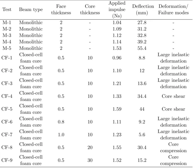
Table 1 Summary of dynamic experiments performed on monolithic and sandwich beams.
Test Beam type Face thickness Core thickness Applied impulse (Ns) Deflection (mm) Deformation/ Failure modes
M-1 Monolithic 2 - 1.04 27.8
-M-2 Monolithic 2 - 1.09 31.2
-M-3 Monolithic 2 - 1.12 32.8
-M-4 Monolithic 2 - 1.14 39.2
-M-5 Monolithic 2 - 1.53 55.4
-CF-1 Closed-cell
foam core 0.5 10 0.96 8.8
Large inelastic deformation
CF-2 Closed-cell
foam core 0.5 10 1.10 12
Large inelastic deformation
CF-3 Closed-cell
foam core 0.5 10 1.21 13.6
Large inelastic deformation
CF-4 Closed-cell
foam core 0.5 10 1.33 34.4 Core shear
CF-5 Closed-cell
foam core 0.5 10 1.59 44 Core shear
CF-6 Closed-cell
foam core 0.8 10 1.11 9.2
Large inelastic deformation
CF-7 Closed-cell
foam core 1.0 10 1.23 5.6
Large inelastic deformation
CF-8 Closed-cell
foam core 0.5 20 1.55 30.4
Core compression
CF-9 Closed-cell
foam core 0.5 30 1.52 15.2
Core compression
Figure 5 Effect of key parameters on the structural response (normalized deflectionW¯ =W/L, normalized impulseI¯=I/(L√ρ
fσf Y)).
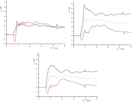
deformation. The maximum stretching deformation occurs at the centre, and it reduces with the increase of the distance from the centre. Note that an abnormal signal recorded from gauge 1 may be caused by core shear with interfacial failure mode, which prevented the continuous bending and stretching deformation in the adjacent area. The average value of strain signal at same point of front and bottom face indicates the strain generated by longitudinal plastic membrane force (the broken line in Fig.6). Similar experimental result was observed by Zhao et al. in the literatures [8, 11].
3 FE MODEL
The numerical simulations were conducted using LS-DYNA 970 software, which is a power-ful FEA tool for modeling non-linear mechanics of solids, fluids, gases and their interaction. Since the sandwich beam is symmetric about x-z and y-z planes, only a quarter of the beam was modeled, as shown in Fig.7. The face-sheets were meshed using Belytschko-Tasy shell element, while the core was meshed using solid element. The entire model comprises 41572 nodes and 40935 elements. In the simulation, the mechanical behavior of aluminum alloy was modeled with material type 3 (*MAT PLASTIC KINEMATIC) in LS-DYNA, which is a bi-linear elasto-plastic constitutive relationship that contains formulations incorporating isotropic and kinetic hardening. The aluminum foam was modeled by material model 63 of LS-DYNA (*MAT CRUSHALBE FOAM), and its stress-strain curve is shown in Fig.8. Material proper-ties of sandwich beam were summarized in the Table 2. The bolts used in the tests to clamp the beams to the fixture were represented by nodal constraints in the numerical model. Automatic, surface-to-surface contact options were generally used between the projectile and front face.
Figure 7 FE model of the 1/4 beam.
Figure 8 Stress-strain curves for the foam materials.
4 SIMULATION RESULTS AND DISCUSSION
4.1 Deformation mode
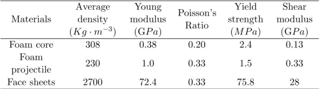
Table 2 Material property of sandwich beam with metal foam core
Materials
Average density (Kg·m−3)
Young modulus
(GP a)
Poisson’s Ratio
Yield strength
(M P a)
Shear modulus
(GP a)
Foam core 308 0.38 0.20 2.4 0.13
Foam
projectile 230 1.0 0.33 1.5 0.33
Face sheets 2700 72.4 0.33 75.8 28
of sandwich beam were presented and discussed in this section. Due to structural features, the failure of sandwich beam is almost characterized by the large inelastic deformation. The large inelastic deformation modes of sandwich beams obtained from the simulation and experiment are shown in Fig.9. It is found that the thin core often lead to the large global deformation when the applied impulse is small, the local indentation in the impact area can be observed for the thin face sheet sandwich beams. The deformed cores show a progressive deformation pattern, and the deformation mode of sandwich beams with various core thickness (10mm, 20mm and 30mm) is similar. Compression deformation occurred mainly at the centre area of specimen, in which aluminum foams were compressed progressively and microstructures col-lapse layer by layer, and then are fully compacted at the densification strain. A comparison of core compression mode in the experiment and simulation is shown in Fig.10. The shear force is carried mainly by the core of sandwich beam, and plastic collapse by core shear can result, as shown in Fig.11. It is noted that the desired symmetrical shear mode, which occurred at 45 degree from the direction of the neutral plane, is not observed due to heterogeneity of foam material. Moreover, interfacial failure between the core and the bottom face usually accompa-nied core shear failure, which is essentially a result of core fracture, rather than debonding in the interface.
Figure 11 Core shear with interface failure (CF-4).
4.2 Back-face deflection
Since personnel or objects shielded from impact/blast attacks are usually behind the barriers such as sandwich structures, the back-face deflection of specimen is herein considered as the main response of interest. A comparison of the experimental and numerically predicated back face deflections are plotted in Fig.12. It is shown in the figure that the data points are concen-trated around a straight line of a slope equal to 1, thus representing a reasonable correlation between the experimental and numerical results. Therefore, the proposed FE model can be con-sidered as a valuable tool in assessing and understanding the deformation/failure mechanism and predicting the dynamic response of sandwich beams subjected to impact loading.
4.3 Structural response process
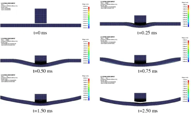
Fig.13 indicates the deformation process of metallic sandwich beam under impact loading. The applied impulse generated by foam projectile is transmitted to the front face of the sandwich beam, and then core is compacted immediately until the final common velocity of the sandwich beam cross-section over the loading patch is achieved. The deformation profile has the shape of a uniform dome, moving out from the centre, transforming into a more quadrangular shape towards the clamped edges. In the succedent phase, the compacted foam projectile is ejected by the reacting force.
Figure 13 A typical process of sandwich beam deformation.
stages: the fluid-structure interaction stage, the core compression stage and finally a combined beam bending and stretching stage. Some FE simulations [9, 13] indicated that the Fleck and Deshpande model may over-estimate or under-estimate the deflection of the sandwich beams under blast loading. These discrepancies have been attributed to the fact that coupling between the stages of the response can cause enlarged or reduced deflections compared with those predicted by the fully decoupled Fleck and Deshpande model. McShane et al [10] performed FE simulations with the couplings between the three stages of response switched on and off and demonstrated that the enhanced performance for sandwich beams observed in their study is primarily a result of coupling between core compression in stage and combined beam bending and stretching in stage of the sandwich beam response. This coupling is most significant in beams with a core of low transverse strength.
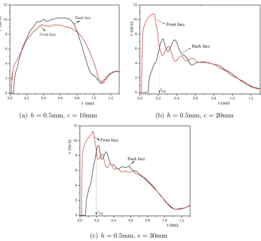
(a)h= 0.5mm,c= 10mm (b) h= 0.5mm,c= 20mm
(c)h= 0.5mm,c= 30mm
Figure 14 Velocity-time histories at the mid-span of the front and back sheet of sandwich beam.
sandwich beam, which is prone to deform globally with no core compression. For the thick sandwich beam, the velocity of front face reaches its maximum value in the early stage of structural response, and decreases gradually due to the compression of core. At the same time, the front and back face velocities equalize early in the deformation history. The core is being compressing untilt=teq, the deformed shape of the sandwich beam varies from a flat profile to
a dome-like shape with largest transverse deflections at the mid-span. Subsequently, the faces share a common velocity-time response and both the face-sheets are brought to rest during the subsequent sandwich mode of bending/stretching. According to Liang’ research results [9], the coupling between core compression in stage and combined beam bending and stretching in stage of the sandwich beam response is not significant for the tested specimens due to the high core strength. However, sandwich cores of very high strength will not fully densify and this can not result in a loss in bending strength of sandwich beams and give rise to very high support reactions when the front face slams into the back face. Therefore, a deep insight into the coupling of sandwich beam with different core strength and core thicknesses is required to investigate the dynamic response and optimal design of these structures.
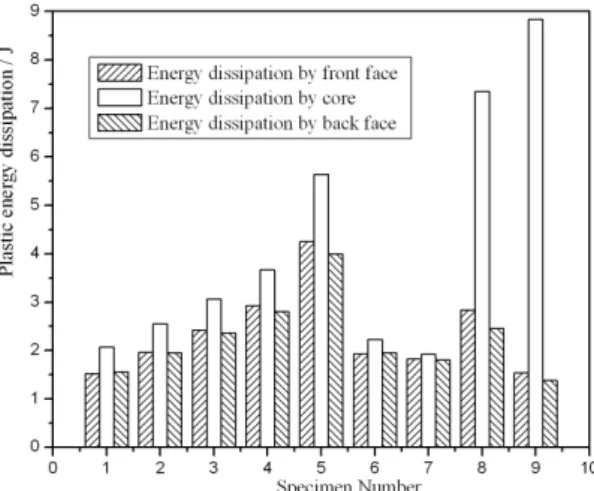
4.4 Energy absorption
Figure 15 Plastic energy dissipation by face sheets and core of sandwich beams.
5 CONCLUSIONS
The dynamic response of clamped metallic sandwich beams under impact loading was inves-tigated experimentally and numerically in this paper. Results show that the deformation and failure mode of sandwich beam is sensitive to its structural configuration and loading intensity. The impact resistance capacity of sandwich beam can be improved by increasing the face-sheet thickness or core thickness. Sandwich beams subjected to dynamic loading can fail in several modes: large inelastic deformation, core compression and core shear with interfacial failure. The dynamic response of sandwich beams is analyzed by using strain gauge testing technique. It is shown that the maximum stretching deformation occurs at the centre, and it reduces with the increase of the distance from the centre. But it is difficult to observe the traveling of plastic hinges according to the recorded strain signals. Numerical results also show that the velocity-time histories of the mid-span of the front and back sheet of sandwich beams are related to not only core strength but also core thickness; and the coupling between core compression in stage and combined beam bending and stretching in stage of the sandwich beam response is not significant for the tested specimens due to the high core strength.
AcknowledgmentsThis work is supported by the National Natural Science Foundation of China (Grant No. 90716005, 10802055, 10972153), Postdoctoral Science Foundation of China, the Natural Science Foundation of Shanxi Province (Grant No. 2007021005) and Program for the Homecomings Foundation and the Top Young Academic Leaders of Higher Learning Institu-tions of Shanxi. The financial contribution is gratefully acknowledged.
References
[1] M. F. Ashby, A. G. Evans, N. A. Fleck, et al. Metal Foams: A Design Guide. Butterworth-Heinemann, Boston, 2000.
[3] A. G. Evan, J. W. Hutchinson, and N. F. Ashby. Multifunctionality of cellular metal systems. Progress in Materials Science, 43:171– 221, 1999.
[4] Zhu Feng, Zhao Longmao, Lu Guoxing, et al. Deformation and failure of blast-loaded metallic sandwich panels – experimental investigations.International Journal of Impact Engineering, 35:937–951, 2008.
[5] Zhu Feng, Zhao Longmao, Lu Guoxing, et al. A numerical simulation of the blast impact of square metallic sandwich panels. International Journal of Impact Engineering, 36:687–699, 2009.
[6] N. A. Fleck and V.S. Deshpande. The resistance of clamped sandwich beams to shock loading. J. Appl. Mech., 71(3):386–401, 2004.
[7] L. J. Gibson and M. F. Ashby. Cellular Solids: Structure and Properties. Cambridge University Press, Cambridge, 2nd edition, 1997.
[8] M. Koller, Zhao Longmao, Mu Jianchun, et al. Experiments on the impact of cylindrical projectiles on thin spherical caps.Acta Mechanica Solida Sinica, 12(3):218–223, 1991. (In Chinese).
[9] Y. Liang, A.V. Spuskanyuk, S.E. Flores, et al. The response of metallic sandwich panels of water blast. J.Appl. Mech., 74:81–99, 2007.
[10] G.J. McShane, V.S. Deshpande, and N.A. Fleck. The underwater blast resistance of metallic sandwich beams with prismatic lattice cores.J.Appl. Mech., 74:352–365, 2006.
[11] Li Qingming and Zhao Longmao. Experimental investigation of clamped shallow arches subjected to projectile impact.Explosion and shock waves, 11(3):238–243, 1991. (In Chinese).
[12] X. Qiu, V. S. Deshpande, and N. A. Fleck. Dynamic response of a clamped circular sandwich plate subject to shock loading.Journal of Applied Mechanics, 90:637–645, 2004.
[13] T. Rabczuk, J.Y. Kim, E. Samaniego, et al. Homogenization of sandwich structures. Int. J. Numer. Methods Eng., 61(7):1009–1027, 2004.
[14] D. D. Radford, G. J. McSHane, V. S. Deshpande, et al. The response of clamped sandwich plates with metallic foam cores to simulated blast loading.International Journal of solids and structures, 43:2243– 2259, 2006.
[15] C. A. Steeves and N. A. Fleck. Collapse mechanisms of sandwich beams with composite faces and a foam core, loaded in three-point bending. Part I: analytical models and minimum weight design. International Journal of Mechanical Sciences, 46:561–583, 2004.
[16] V. L. Tagarielli and N. A. Fleck. A comparison of the structural response of clamped and simply supported sandwich beams with aluminium faces and a metal foam core. Journal of Applied Mechanics, 72:408–417, 2005.
[17] V. L. Tagarielli, N. A. Fleck, and V. S. Deshpande. Collapse of clamped and simply supported composite sandwich beams in three-point bending. Composites: Part B, 35:523–534, 2004.