INTRODUCTION
Since the early 90s, much attention has been given to the synthesis of materials with porous structure in the mesoporous range and narrow distribution range from 2 to 10 nm. The fi rst materials of this type were called M41S in 1992 by the Mobil Oil Co. group. This incredible discovery employing ionic surfactants that interact with inorganic ions forming an orderly mesoporous network, opened new fi elds in the area of engineering of new materials, catalysis and molecular accessibility, which were not achieved before due to the limited pore size of zeolites and other microporous materials.
The use of ionic surfactants together with inorganic ions to promote orderly mesoporosity was also employed in clays. Its main purpose, after calcination to remove the surfactant, was to increase the accessibility and sieving of molecules of the interlayer region combined with the properties of clays, such as acidity, ion exchange, etc. Firstly described in 1995 by Galarneau et al and due to their lamellar structure with mesoporous cylinders similar to MCM -41 in the inter-gallery region, they were called Porous Heterostructured Clays - PCHs. Although they were discovered 17 years ago, studies on PCHs are relatively new and many challenges
remain. It is observed in literature that there are only studied on this topic, and no detailed review has been reported. This study aims to describe, from a historical perspective, the evolution of synthesized materials based on clay to the discovery of PCHs. Considerable attention was given to the synthesis aspects such as the role of each reagent in the formation of PCHs, their main applications, as well as the characterization techniques that help prove the formation of these materials.
From porous clays to porous heterostructured clays
Clays: clays can be defi ned as a natural and earthy product, consisting of very fi negrain components including,for being fundamental, clay minerals. In a more scientifi c defi nition, it is considered a rock mainly composed of clay minerals, which can be found with other minerals such as quartz, feldspar, mica, calcite, organic material and other impurities. It can be physically characterized by having high content of particles having equivalent spherical diameter (d.s.e) less than or equal to 2 μm. When they are pulverized and mixed with enough amount of water, they become plastic and upon drying, they become stiff and consistent. At elevated temperatures above 1000 °C, clays acquire great hardness
Porous heterostructured clays – recent advances and challenges - revisão
(Argilas porosas heteroestruturadas - avanços e desafi os recentes -
revisão)
A. J. Schwanke1, S. B. C. Pergher1,2
1Materials Science and Engineering Program, 2Department of Chemistry
Federal University of Rio Grande do Norte, Campus Lagoa Nova, Natal, RN 59072-970 [email protected], sibelepergher@gmail.
Abstract
Porous heterostructured clays – PCHs – are lamellar solids with acid and adsorptive properties serving as catalysts or catalyst supports formed on a template mechanism. This work provides information about porous heterostructured clays. Historical aspects of the development of lamellar solids to porous heterostructured clays will be discussed, and detailed information on synthesis and applicationaspects, as well as on the infl uence of eachreagent on these materials and the characterization techniques used to prove their formation will be given.
Keywords: porous heterostructured clays, PCHs, lamellar solids.
Resumo
Argilas porosas heteroestruturadas - PCHs - são sólidos lamelares com propriedades ácidas e adsortivas que servem de catalisadores ou suporte de catalisadores formados pelo mecanismo de gabarito. O presente trabalho traz informações sobre as argilas porosas heteroestruturadas - PCHs. Aspectos históricos sobre o desenvolvimento dos materiais lamelares até os PCHs são abordados, bem como informações detalhadas sobre aspectos de síntese, aplicações, a infl uência de cada reagente na formação destes materiais e as técnicas de caracterização essenciais utilizadas para comprovar a sua formação.
[1]. Chemically, clay minerals of are aluminum / hydrated magnesium silicates and may contain other elements such as iron, calcium, sodium, potassium and others of fi brous or layered crystalline structure [2].
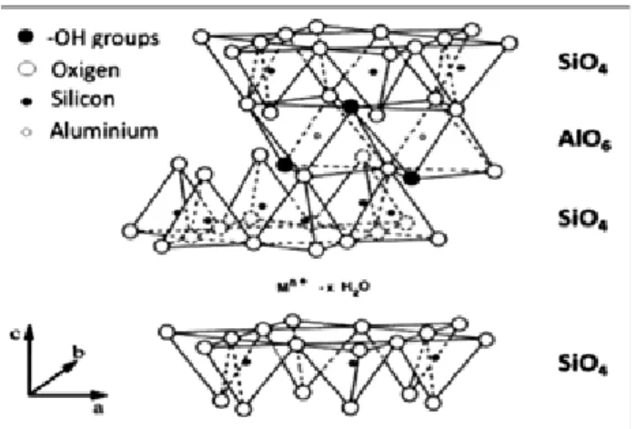
Smectite clays: the class of smectites is within the group of clay minerals. Fig. 1 shows the following clay materials: montmorillonite, nontronite, beidellite, saponite, hectorite and sauconite. Smectites have been the most used both in scientifi c research and in industrial applications due to properties that will be described later. Here, in particular, we will deal with clays for catalytic and adsorption purposes.
As seen in Fig. 1, the union of a tetrahedral silicon sheets and an aluminum octahedral sheet results in a 2:1 layer also called TOT. These lamella grow in the directions of a andb axisand are piled with a certain order, or not along the c-axis. Smectites may show isomorphous substitution in a moderate percentage of silicon by aluminum in tetrahedral positions (beidellites), and the population of octahedral positions can be aluminum (montmorillonite), iron (nontronite), magnesium (hectorite) and others, alone or in combination. All octahedral positions may be fi lled (trioctaedral forms) or only two thirds of them (dioctaedralforms). The population of cationic positions is such that the blades are electrically unbalanced with a defi ciency of positive loads
that is compensated by hydrated cations accommodated between the lamellar structure. Thus, the layers (A) form a clay particle (B). Clay particles, in turn, can be piled to form aggregates (C), generating the interparticle space. The assembly of aggregates (A) forms interaggregate spaces as seen in Fig. 2.
Properties of smectites
The use of clays in a given application depends directly on their properties. The main properties of smectites will be discussed below.
Cation exchange capacity: cation exchange capacity (CEC) is defi ned as the amount of exchangeable cations that a clay mineral can absorb at a specifi c pH. This is a measure of the total number of negative charges present, also including isomorphic substitutions within the reticulate, broken bonds at the edges and outer surfaces and dissociation of accessible hydroxyl groups [4]. F o r equivalent concentrations, some cations are adsorbed more strongly than others and may be ordered in sequence, thus,cationsfrequently found may show the following order: H < Al <Ba<Sr< Ca < Mg < NH4< K < Na < Li. The exchange power of a cation will be greater the greater its valence and the lower its hydration. For monovalent cations, the sequence would be H+>Cs+>Rb+> NH4+> K+> Na+> Li+. For divalent cations, the sequence would be as follows [ 1 ]: H+>Cs+> Rb+> NH4+> K+> Na+> Li+.
Table I shows the cation exchange capacity values for different clays, showing that montmorillonite, class of smectites, have the second highest cation exchange capacity.
Acid surface: smectite clays can have both Brönstedacidic sites such as Lewis, which correspond to water molecules that are coordinated to the compensation cations, hydroxyl groups of the edges of crystals and hydronium ions. Lewis sites correspond to coordinated unsaturated aluminum and magnesium ions and their own exchangeable cations, especially transition metals. Both acid sites depend on the clay’shydration state. Thus, the strong Brönsted sites of smectite are derived from the dissociation of water coordinated to compensation cations. The dissociation of Figure 1: Idealized structure of smectite clay (2:1 ) [3].
[Figura 1: Estrutura idealizada de uma esmectita (2:1) [3].]
Figure 2: Different conformations of clays.
[Figura 2: Diferentes conformações das argilas.]
Table I - Cation exchange capacity of different clay minerals. Adapted [4].
[Tabela I - Capacidade de troca catiônica de diferentes argilominerais. Adaptado [4].]
Clay mineral CEC
(mEq/100g)
Kaolinite 3-15
Halloysite 5-50
Ilite 10-40
Chlorite 10-40
Montmorillonite 60-150
hydrogen ions from the hydrated water on the polarizing effect of the metal ion is as follows (A):
[M(OH2)x]n+ → [M(OH)(OH 2)x - 1]
(n - 1)+ + H+ (A) where M is the cation of charge n+ coordinated to x water molecules.
The acid strength of some ions decrease in the polarization order, decreasing with size and increasing with charge, therefore, the order would be Fe3+< Al3+< Fe2+< Mg2+< Ca2+< Ba2+< Li+< Na+< K+.
Cations fully dehydrated behave as Lewis acids. For example, in adsorption, if the exchangeable cation is a transition metal, or a Lewis acid, and the adsorbate is a strong electron donor, a coordination complex d in the interlayer region is formed, stabilizing the adsorption process [5].
Pillared clays: with the increase in oil prices in 1973, a great effortwas done for the development of catalytic materials that could process heavy petroleum fractions. Even the external surfaces of clays being active in catalysis, these heavy fractions could not penetrate between the lamella of clays used in the high temperatures used for cracking. Thus, they needed to promote accessibility, structural stability and catalytic activity in the interlayer spacing. The fi rst work using pillared clays was reported in 1955 by Barrer and Macleod [6] and then intensifi ed by Vaughan et al [7], incorporating cations of large sizes between the lamella of clays, so receiving this name, pillared clays or PILCs, Pillared Interlayered Clays. Fig. 3 shows the schematic formation of clay pillars. The top image shows a natural clay with sodium and calcium cations compensating the charges; in the lower right image, these cations are replaced by larger ions, in this case, of charge 7+, increasing the interlayer spacing to 19 Å. When heated, this ion loses protons to lamella to balance their negative charge, so the pillar is transformed into an oxide particle [7]. Pillared clays have specifi c areas, ranging from 50 to 200 m².g-1, are hydrothermally less stable than zeolites but have larger pore volumes, favoring reactions of high-volume molecules [8]. Previously studies describe this topic [3, 9-11].
TSLS - Tubular Silicate - Layered Silicate: imogolite, a mineral of formula SiAl2O3(OH)4 that can be constructed from gibbsite layer to which orthosilicic acid is coordinated with three aluminum atoms through common oxygen atoms, as seen to the left of image (a), Fig. 4. The layer is subsequently wound up into a cylinder (image (a) right) with inner and outer diameters of tubes of approximately 1.0 and 2.4 nm, respectively, as shown in image (b), while its length can reach hundreds of nanometers [12]. This material proposed in 1988 [13] was called TSLS – Tubular Silicate - Layered Silicate and had as peculiarity the microporous channel formed by imogolite interspaced in between the lamellas, as seen on image (c). According to studies [14], this channel has the capacity of adsorbing molecules of kinetic diameter up to 1.0 nm. In fact, the fi rst material in whichthe interspersed material acted jointly with clay lamellas as moleculeselectors wassynthesized.
In imogolite interspersed with smectite clays such as Na+montmorillonite, basal spacing of 3.40 nm was obtained, which was approximately 2.40nm the outer imogolite diameter and approximately 0.96 nm the thickness of the montmorillonitelamella. The mode of interaction between the tubular surface of imogolite and clay lamellae involve hydrogen bonds. This material also obtained specifi c area of Figure 3: Pillared clay formation.
[Figura 3: Formação de uma argila pilarizada.]
Figure 4: Image(a), perspective projection of the piling of a gibbsite layer and orthosilicic acid and the formation of imogolite tube, adapted from literature [15]. Image (b) shows the internal and external diameters and distances from imogolite and two silanol group in the same section = 0.26 nm and between two adjacent section of silanol groups = 0.44 nm, adapted from reference [16]. Image (c) shows the TSLS material interspaced between montmorillonite clays, adapted [13].
approximately 300 m².g-1and thermal stability of 400 ° C [13]. FSM-16-Folding Sheet Mechanism: this material called FSM-16-Folder Sheet Mechanism number 16 has been reported [17] and is regarded as the fi rst study to report the synthesis of a material with high specifi c area derived from a silicate using surfactant in hydrothermal medium (Fig. 5). Kanemite of formula NaHSi2O5.3H2O is a material of lamellarform that can be found naturally or synthesized in laboratory. Its layers consist of monolayers of SiO4 tetrahedra, with interlayer space occupied by sodium ions. In a process of ion exchange, organic cations (CnH2n+1(CH3)3N+) are inserted into the interlayer region, with the occurrence of folding of lamella and the condensation of silanol groups. After calcination at 1000 °C the mesoporous material is formed on specifi c areas of 1,100 m².g-1and average pore diameter of 2.8 nm, thus demonstrating its high porosity and thermal stability [18]. It is also emphasized that this mesoporous material, FSM-16, was proposed in 1990, at the same time the famous mesoporous materials of family M41S were reported by Mobil. But due to a limited description of the synthesis and characterization of this material,there were not many advances regarding the publications and patents of Mobil [19].
Porous heterostructured clays- PCHs: porous heterostructured clays-PCHs were synthesized [20]. Fig. 6 shows the formation of porous heterostructured clays.
Li+ fl uorohectorite smectite clay was used [20]. In this process, long chains of quaternary ammoniun cationic, surfactants (Q+ = C
nH2n+1N(CH3)3
+, where n vary from 10 to 16, are introduced into the interlayer space of the clay by the cationic
exchange of Li+ ions present in clay in order to compensate for the negative charge of sheets. Then co-surfactants or neutral chain amines ranging from n = 6 to 16 (CnH2n+1NH2) were added, and together formedmicelletemplates in the interlayer region. Once the silicon source wasadded, TEOS, which causes a partial displacement of the neutral amine, polymerized silicate species are formed on the outer surface of cylinders analogous to the micelles formed by the template mechanism of MCM -41 [22], forming a dense silicon network. The surfactant fraction in the micelle is determined by the lamella charge of the clay. The calcination process to remove the organic template resulted in a porous silica network interposed between the lamellae. It is noteworthy that the formation of porous heterostructured clays is based on a template mechanism and not on a pillaring mechanism. This is because the pore system generated in the interlayer space is promoted by the use of surfactants and co-surfactants, which determine the pore size, whose maximum values range from 1.4 to 4.0 nm [23], thus establishing a clay: amine: silica relationship. Otherwise, the formation of silica aggregates in the interlayer region would depend only on the clay: silica relationship [24]. One of the main advantages of using PCHs compared to other materials such as pillared clays is that the density of the interspaced material is controlled by the mounting mechanism, whatever the initial amount of silica [25].
The role of each reagent in the synthesis: the synthesis of PCHs uses a source of lamellar silicate, usually synthetic montmorillonite or saponite clays, surfactant, co-surfactant and a silica source, TEOS. The function of each reagent in the synthesis will be discussed below.
Clay: the type of clay infl uences the synthesis of PCHs. Depending on the clay used and its dimensions, two types of mechanisms may occur. In natural clays, the preferred piling of layers of average size of 1μm is parallel and the silica network is located between the lamella, generating a two-dimensional porous structure shown in Fig. 7a. For synthetic saponite clays, hydrolysis and polymerization of TEOS around the micelles do not necessarily occur in the interlayer space of the clay due to the small size of sheets of up to 50 nm, generating mutual edge and edge-to-face interactions, resulting in a type of individual piling of lamellae anchored by the growth of the silicate network in a three-dimensional structure, as shown in Fig. 7b.
Figure 5: FSM-16 mesoporous material formation mechanism. Adapted [18 ].
[Figura 5: Mecanismo de formação do material mesoporoso FSM-16. Adaptado [18].]
Figure 6: Porous Heterostructured Clays - PCHs formation scheme. Adapted [21].
[Figura 6: Esquema de formação das argilas porosas heteroestruturadas - PCHs. Fonte: adaptado [21].]
Figure 7: Stacking mechanisms of natural clays (a) and synthetic saponite clays (b). Adapted [26, 27].
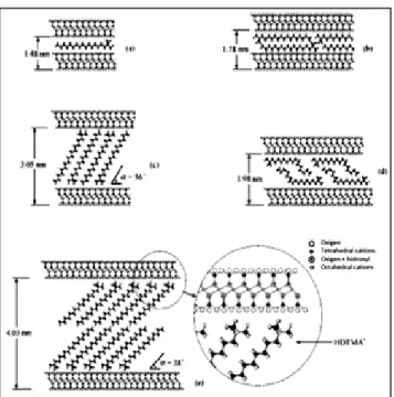
Surfactant: surfactant plays an important role for being responsible to compensate for the negative charges of lamellae, allowing access to the interlamellar region, control the size of mesoporous cylinders formed in the intra-gallery region [28]. Generally, for the synthesis of PCHs, the amount of surfactant used is above the clay CEC [23]. Controlling the increase in the surfactant concentration, one can foresee different surfactant conformations in the interlayer region with the aid of X-ray diffraction, as shown in Fig. 8. For the synthesis of PCHs, the preferred ions are the ammonium quaternary with at least six carbon atoms of chain length. Secondary and tertiary ions may also be used, but primary ions are not effective in the formation of PCHs [23]. This is due to the size of the head group, which needs to be large to form micelles, the same occurs for the formation of MCM-41 [29]. Both the surfactant and the co-surfactant, which will be explained later, will assist in the formation of the silica network by electrostatic interactions and hydrogen bonds between the ionicsurfactant and the neutral amine and the precursor [23].
Table II shows the variation surfactant (Q +) and amine and formation of PCHs before and after calcination. As noted, there is a linear relationship between the size of the carbon chain of the surfactant and co-surfactant and pore size. By using HDTMA+ and dodecylamine, speci
fi c areas of 750 m².g-1 and pore size of about 2.20 nm are obtained.
In a recent study [32], the authors reported that it is possible to synthesize PCHs without the addition of co-surfactant. Through IR analysis, the rearrangement of CTAB
molecules into cylindrical liquid crystals is observed. X-ray diffraction and transmission electron microscopy analyses of the calcined materials show basal spacings near 3.10 nm and pore diameter calculated by BJH 2.00 nm.
Inorganic precursor: the inorganic precursor is preferably a source of silicon, tetraethyl orthosilicate (TEOS). Metal oxides such as alumina, zirconia and titanium may also be used alone or mixed [23]. By adding TEOS in the synthesis, it is hydrolyzed and condensed successive times to form polymeric species with Si-O-Si bonds, thus three reactions are typically used to describe this process [33]: hydrolysis
≡Si – O(CH2CH3) + H2O ↔≡Si – OH + CH3CH2OH (B) esterifi cation
condensing alcoholic
≡Si – O(CH2CH3) + HO – Si≡↔
≡Si – O – Si≡ + CH3CH2OH (C) alcoholysis
water condensation
≡Si – OH+HO – Si≡ ↔ ≡Si – O – Si≡ + H2O (D) hydrolysis
Once the extra-gallery water concentration is too low, the base catalyzed hydrolysis of TEOS is more rapid in the interlayer region and this minimizes the formation of extra-gallery silica. Therefore, the hydrolysis is favored in part by the removal of water present inside the lamella [31]. Therefore, in practically all procedures for the synthesis of PCHs, theclay expanded with quaternary ammonium cations (Q+-clay) is dried at room temperature, since if water is completely removed, TEOS will not be hydrolyzed and the intercalated silica will not be formed [32].
Table III shows the amine: TEOS molar ratio, and it is observed that the best values are found in the 7.5 and 1ratios.
Surfactant removal: it is not wrong to say that the proposed routes for the removal of the structure directing agent of PCHsare very similar to those of MCM-41. Nevertheless, efforts are still directed to the main member of the family M41S, as can be seen in Table IV, noting that in some cases, it is possible to recover the surfactant for reuse. As seen, the study fi eld for PCHs, compared to MCM -41, still needs more attention and can serve as future studies.
Chmielarz et al [21], before submitting PCHs to the calcination step, studied by thermogravimetry coupled with mass spectrometer, the thermal degradation of surfactant present in the pore system of PCHs and noted that several products are formed. At 184 °C, degradation of surfactant and co-surfactant molecules is observed. The authors claim that the degradation of amines at this temperature is favored by the presence of acid sites located on the surface of the clay lamellae, which are known to be catalytically active in the process of hydrocarbon cracking. At temperatures above 230 °C, there are ionic species CH2=NH2+ formed by the fragmentation of co-surfactant hexadecilamina. At approximately 280 °C there is the evolution of trimethylamine N(CH3)3, probably formed by the degradation of hexadecyltrimethylammoniun cation. At 346 ºC, intensive oxidation of organic matter deposited Figure 8: Different accommodations of surfactant HDTMA+. (a)
lateral monolayer, (b) lateral bilayer, (c) paraffi n monolayer, (d) pseudotrilayer, (e) paraffi n bilayer. Adapted [30].
[Figura 8: Diferentes acomodações do surfactante HDTMA+.
within the pores is observed. These authors varied the calcination temperatures at 550, 600 and 800 °C. The optimum calcination temperature was set at 600 ºC. At lower temperatures, an incomplete removal of carbon deposits is observed, but at 800 °C, a partial collapse of the pore structure may occur.
Another route used in PCHs is the extraction using solvents. This technique has been successfully used for HMS materials [42], where mesoporous structures are formed by S0I0 interactions between silica oligomers and neutral amines. As these interactions are relatively weak, structure directing agent can be extracted under milder conditions. In
the case of PCHs and MCM -41, the interactions between silica oligomers and surfactant are based on S+I-electrostatic forces, which are usually too strong to allow the extraction with a simplepolar solvent.
Therefore, the introduction of H+ or NH 3
+cations improved extraction effi ciency because they replace the interaction of cationic surfactants by compensating the negative charge of the silicate network. Table V shows the percentage of template extracted for PCHs synthesized using natural montmorillonite clays under different types of extraction. Extraction with solvent generates a remaining amount of surfactant present in the pores, needing to be Gallery = basal spacing - lamella thickness ( 9.60 nm )
HDTMA+ = C 16H33N
+(CH
3)3, DDTMA + = C
12H25N +(CH
3)3, DTMA + = C
10H21N +(CH
3)3
Example Surfactant Co-surfactant Dry product gallery (nm)
Calcined product gallery (nm)
ABET (m².g-1)
H & K (nm)
1 HDTMA+ C
6H13NH2 2.22 1.49 550 1.5
2 C8H17NH2 2.24 1.84 680 1.8
3 C10H21NH2 2.84 2.24 800 2.1
4 C12H25NH2 3.44 2.34 750 2.2
5 DDTMA+ C
8H17NH2 2.90 1.70 600 1.6
6 C10H21NH2 3.10 2.00 660 1.8
7 DTMA+ C
8H17NH2 1.76 1.40 560 1.4
8 C10H21NH2 2.39 1.43 600 1.4
Table II - PCHs formed with different variation between surfactants and co-surfactants. Adapted [23]. [Tabela II - PCHs formados com diferentes variações de surfactante e co-surfactantes. Adaptado [23].]
Example Surfactant Dry product gallery (nm)
Calcined product gallery (nm)
Amine: TEOS molar ratio
ABET (m².g-1)
H & K (nm)
9 DTMA+ 2.74 0.27 0.5 200 0
10 2.44 0.27 5.0 260 0
11 2.44 1.39 7.5 560 1.4
12 2.34 1.44 10.0 650 1.4
13 DDTMA+ 2.94 0.27 0.5 170 0
14 2.64 1.64 5.0 350 0
15 2.64 1.8 7.5 660 1.7
16 2.64 1.8 10.0 750 1.7
17 HDTMA+ 2.84 0.25 0.5 300 0
18 2.84 2.0 5.0 350 0
19 2.84 2.10 7.5 800 2.1
20 2.84 2.14 10.0 850 2.1
Table III - PCHs formed with different variation of co-surfactants and TEOS. Adapted [23]. [Tabela III -PCHs formados com diferentes variações de surfactante e TEOS. Adaptado [23]. ]
Gallery = basal spacing - lamella thickness (9.6 nm) HDTMA+ = C
16H33N +(CH
3)3, DDTMA + = C
12H25N +(CH
3)3, DTMA + = C
10H21N +(CH
followed by calcination for its complete removal.
After solvent extraction, the material was submitted to hydrothermal treatment in mild steam conditions (N2fl ow of 25% steam for fi ve days) indicating excellent hydrothermal stability, where only at 700 °C there is degradation of its structure.
Properties of PCHs
Cation exchange capacity in porous heterostructured clays: in the calcination step, protons generated from the decomposition of the surfactant can offer possibilities for the modifi cation of PCHs with different cations or transition metals for the fi ne adjustment of the catalytic or adsorptive properties and move to unoccupied positions within the clay lamellae (octahedral vacancies in dioctahedral clays or defects in trioctaedral clays) and as a consequence, reduce its CEC. The latter may be limited by the exchange of protons by NH4+ cations, which are too large to migrate into the lamellae. Benjelloun etal [44] studied the CEC of PCHs with different methods and concluded that adsorption on ammonia fl ow, NH3, generating NH4+ ions and later
exchange by K+ ions, proved to be the most ef
fi cient method, with values of 0.20 mmol/gPCH and 0.55 mmol/gPCH for calcined PCHs and with process of solvent extraction, respectively.
Acidity: PCHs interspersed with silica are intrinsically acidic due to the exchange of Na+, Ca2+ or Li+ ions by cationic surfactants and subsequently by proton H+, generated by calcination or extraction of surfactants, which will compensate the charges of clays. One way to increase acidity is through alumination. In a post-synthesis step, using synthetic saponite clay and aluminum chloride, AlCl3, or sodium aluminate, NaAlO2, in Si/Al molar ratio 5:10, PCHs showed higher catalytic activity than Al-MCM-41 and Al-HMS under similar conditions, as shown in Table VI.
The increase in acidity may also be achieved by adding titanium, in this case, titanium tetraisopropoxide, TIP, which added along with the silica source in the surfactant/
Solvent extraction Extracted
template (%)
EtOH (50 mL) 24
EtOH (50 mL) / HCl (5 mL, conc.) 71 EtOH (50 mL) / NH4-acetate (0.5 g) 68 EtOH (50 mL) / Na-acetate(0.5 g) 82 Acetone (45 mL) / HCl (5 mL, conc) 82 MeOH (45 mL) / HCl (5 mL, conc) 91 Table V - Percentage of template extraction over different extractions. Adapted [43].
[Tabela V - Porcentagem de extração de template em diferentes extrações. Adaptado [43] .]
Method Procedure Removal (%) Reuse Ref.
Sonication Ultrasound 15 min + 40 ºC 94 X [34]
Ion Exchange Alcoholic solution + ammonium nitrate + 15 min + 35 ºC
100 X [35]
Extraction using super-critical fl uid
Pressure 350 bar + methanol fl ux 0.2 mL.min-1 + 85 ºC
93 X [36]
Photo calcination by UV
Ultraviolet ( = 172 nm) + 105 Pa + 30 min
100 [37]
Oxidation by Ozone Ozone Generator + 14 h 94.5 [38]
Heating in H2fl ow Hydrogen + 250 ºC + 15 h 100 [39]
Plasma Dielectric barrier plasma
discharge
96.3 [40]
Microwave Microwave Digestion + 5 min. --- [41]
Table IV - Alternative methods of surfactant removal from mesoporous materials.
[Tabela IV - Métodos alternativos de remoção de surfactantes para materiais mesoporosos.]
Cumene cracking conversion a
Catalyst Aluminizing
agent
Conversion rate (%)
H+saponite 20.2
SAP - PCH 36.2
Al-PCH-10 AlCl3 55.2
Al-PCH-10 NaAlO2 58.8
Al-PCH-5 NaAlO2 66.7
5% Al-HMS NaAlO2 48.9
5% Al-MCM-41 NaAlO2 34.5
Table VI - Cumene cracking conversion over different materials. Adapted [31].
[Tabela VI - Conversão de craqueamento do cumeno em diferentes materiais. Adaptado [31].]
areaction temperature 300 °C , 200 mg of catalyst and 4.1 μmol/min
co-surfactant/TEOS/TIP molar ratio of 1/20/150/0, 1/20/14 8.5/1.05, 1/20/142.5/7.5 and 1/20/135/15, provide increased Lewis acidity and mainly in the Brönsted acidity, evidenced by the programmed temperature of ammonia desorption and IR spectroscopy with pyridine adsorption [45]. Another way to increase the acidity is the use of acid clays for the formation of PCHs, calls PAACH, Porous Acid-Actived Heterostructured Clays. These clays, which are determined by programmed temperature of cyclohexylamine desorption may be at least 30% more acidic than the PCHs due to the increased acidity of lamella after the acid treatment, or possibly, a loss of aluminum present in the octahedral sheet incorporated in the silica network of the interlayer space [46].
Characterizations
X-ray diffraction: the characterization of PCHs by X-ray diffraction is an information technique in the fi eld of materials obtained by clay intercalation, allowing the determination of the basal spacing and the ordering degree of the material. Fig. 9 shows the typical diffraction pattern of PCHs calcined at 600 ºC, the natural montmorillonite clay as sodium and uncalcined PC. The peak d001 plane is characterized by basal spacing. For sodium montmorillonite natural clay, the peak refl ection 2 = 6.83° corresponds to the basal spacing of 1.26 nm (schema a). The refl ection at 2 = 27 is attributed to the presence of quartz impurities present in the clay. The basal spacing of layered materials depends on the lamella thickness and on the interlayer distance and thus the thickness of the montmorillonite lamella is estimated at about 0.96 nm [13] and 0.30 nm is characteristic of hydrated clays.
When there is deposition of surfactants andco-surfactants, as well as the formation of the silica in the interlayer region of the clay, a displacement of the d001 plane for smaller angles showed that the basal spacing
was increased. For uncalcined FCHs, the basal spacing is 3.74 nm, reducing 0.96 nm of the lamella thickness, 2.78 nm, indicates that the hexadecylamine molecules, the co-surfactant, are oriented perpendicularly to the clay lamellae, suggesting that they have cylindrical shape in the interlayer space (scheme c), since this value is twice the size of the hexadecylmanine molecule, which is approximately 1.44 nm (diagram b). In the same diffraction pattern, a peak of low intensity with basal spacing of 0.98 nm is detected, which can be attributed to lamellar pilingnot separated by the interlayer spacing, which is an effect than is possible when protons or other small dehydrated cations migrate from unoccupied octahedral positions, resulting in the neutralization of the negative charges of clay lamella [47]. When calcined (scheme d), the material does not change the position of the characteristic peak of the basal spacing; however, the refl ection intensity is relatively reduced, featuring a non- parallel arrangement of the clay lamella, as template decomposition occurs in the calcination, which is an exothermic process, and overheating of the sample can cause disturbances in the lamellae arrangement.
Some studies on the synthesis of PCHs have reported the diffi culty of detecting the diffraction peaks when oriented and non-oriented samplers are used [28, 48]. This is because, as already reported [49], such materials have low ordering and long range. According to these authors, this low ordering can also be complemented by the analysis of high-resolution transmission electron microscopy, where the domains of lamella can be observed, as well as the different pore domains
X-ray diffraction also assists in detecting other phases that compete with PCHs. As they use engineering similar to MCM-41 - using surfactants as structure directing agent and TEOS as inorganic precursor - if the synthesis parameters are not controlled, materials with hexagonal ordering can be formed and their characteristic refl ections are sensitive to X-radiation [50].
N2 adsorption and desorption: this technique is the most widely used to determine the surface of catalysts. Characteristics such as volume, geometry and size can be determined by adsorbing probe molecular such as N2, Ar, CO2 and He. Among them, N2 at temperatures of -196 ºC is still the most widely used [51]. Furthermore, the technique also shows the measured specifi c area related to micro, meso and macroporosity. To determine the volume of the adsorbate monolayer (Vm) and the specifi c area, the model developed by Brunauer, Emmett and Teller (BET) [52] is still the most widely used and is given in equation D. As PCHs generally have combined structure of micro and mesopores, other methods generally used to characterize volume and micropore size distribution of PCHsare Horvath-Kawazoe, HK [53] combined with the method proposed by Barrer, Joyner and Halenda, BJH, for volume and distribution of mesopores [54].
ABET= nm .A .NA . 10-18m².g-1 (E) where nm = number of adsorbed molecules forming the Figure 9: X-ray diffraction patterns of calcined PCHs, uncalcined
PCHs and sodic montmorillonite clay. Schematic representation of basal spacing of sodic montmorillonite clay (a), hexadecilamine molecules perpendicularly oriented in the clay (b), hexadecilamine molecules in a cylindrical shape (c), PCH calcined at 600 ºC (d). Adapted [45].
monolayer. A is the cross sectional area of the gas molecule N2 = 0.162 nm ². NA is the Avogadro’s number.
Fig. 10 shows the N2 adsorption/desorption isotherm and
the pore size distribution with HK-BJH methods combined of a PCH sample calcined at 550 °C for 6 h. According to the authors, this isotherm resembles type II with an increase in the amount of volume adsorbed at relative pressures < 0.02 indicative of micropores. The upward deviation of pressure from 0.02 to 0.3 and the almost linear part located in approximate relative pressures from 0.05 to 0.25 are indicative of mesopores with sizes in the small mesopores zone or in the super-micropore region (between 15 and 25 Å). Based on these characteristics, PCHs are the only materials that combine micro-and mesoporosity [44].
Transmission electron microscopy - TEM: previous
Figure 12: Alkylation of 2,4-Di-tert-butylphenol (BP) with Cinnamyl alcohol (CA). Adapted [57].
[Figura 12: Alquilação de 2, 4-di-tert-butilfenol (BP) com álcool cinamílico. Adaptado [57].]
Figure 10: N2 adsorption/desorption isotherms and pore size distribution combining HK and BJH methods. Adapted [44].
[Figura 10: Isotermas de adsorção e dessorção de N2 e distribuição de tamanho de poros combinando os métodos de HK e BJH. Adaptado [44].]
0.08
600
400
200
0 0
Relative pressure (P/P0) 0.2 0.4 0.6 0.8 1
Adsortion Dv (r)
0.06
0.04
0.02
0
0 10 20 30 40
Pore radius (A)
studies have reported the diffi culty of obtaining MET imagesof PCHs [20]. Although clay lamellae can be easily identifi ed, the pore structure in the intra-gallery region is more diffi cult due to the turbostatic nature of these materials, or when there is a random rotation or translation of the individual layers relative to each other.
Fig. 11a is a typical TEM image of a PCH derived from saponite clay of a sample sectioned along the ab plane with the aid of microtome. This Figure shows that the larger particles consist of aggregates of layers oriented in all directions. The arrow in the Figure indicates the areas in the interlayer region oriented with ab planes parallel to the optical axis of the microscope. Fig. 11b is a magnifi cation of these areas where the lamellar structure and intra-gallery is clearly evident. In Fig. 11c the clay layers are noticeable in the dark solid lines, in which it could be observed that the pore within one of the galleries have uniform size, as indicated by the arrow; however, this orientation is not persistent, indicating a signifi cant degree of disorder in the structure, as well as awormhole-typedisturbance.
Applications: due to the presence of strong acidic properties, thermal stability and combined structure of micro and mesopores, PCHs offer many perspectives in the acidic catalysis and adsorptive fi elds. Their own inventors in 1997, two years after its discovery reported the fi rst application of PCH. Acting as an heterogeneous acid catalyst, PCHs synthesized with a Li+ fl uorohectorite clay were applied to the selective dehydration reaction of 2-metillbut-3-yn-2-ol (MBOH), which is sensitive to the presence of acid and basic sites of the catalyst surface. Acid sites promote dehydration of MBOH to 2-methylbut-3-yn-1-yne (MBino), whereas basic sites cause the formation of acetone and acetate. In this study, the acidic activity was compared with other materials such as Li+ fl uorohectorite, alumina pillars with fl uorohectorite (APF), commercial acid clay K-10:01 and MCM-41pure silica. As a result, PCHs showed high selectivity (99.9 %) to MBino, indicating that its surface contains acid sites. Li+ fl uorohectorite is highly basic, having as
Figure 11: Electron transmission microscopy micrograph of PCH from saponite clay, sectioned by microtome.
Catalyst Conversion rate (%)
Selectivity (%) Flavan yield (%)
4-tert-butylphenol Flavan
HY 13.3 57.8 11.1 1.5
K-10 47.6 59.7 - <1
H+-Saponite 36.1 87.7 3.3 1.2
PCH-Saponite 36.6 32.1 41.9 15.3
Table VII - Alkylation of 2,4-Di-tert-butylphenol (BP) with Cinnamyl alcohol (CA). Adapted [57].
[Tabela VII - Alquilação Friedel Crafts de fase condensada de 2, 4-di-tert-butilfenol (DBP) com álcool cinamílico. Adaptado [57].]
Application PCH characteristics Year Ref.
Selective catalytic oxidation of ammonia to nitrogen
PCH modifi ed with copper and iron species Clay : synthetic saponite
2006 [21]
Adsorbent of volatile organic compounds (VOCs)
Adsorption with ethanol , methyl ethyl ketone , water, carbon dioxide , ethane, methane and nitrogen in PCH
Clay : Bentonite
2004 [28]
Fischer-Tropsch reaction PCH without the addition of cobalt-impregnated co-surfactant.
Clay : montmorillonite
2012 [32]
Capture of heavy metals (Hg2+) PCH functionalized with 3 -mercaptopropyltrimethoxysilane Clay :fl uorohectorita.
1998 [58]
Epoxidation of alkenes PCH functionalized with chiral complexes of transition metals manganese ( III).
Clay: Bentonite
2010 [59]
Table VIII - Reported applications of PCHs. [Tabela VIII - Aplicações dos PCHs reportadas.]
reaction products acetone (46.5%) and acetylene (36.2%). The study also reveals that the conversions of PCHs (52.7 %) are more active than MCM-41 (11%), APF (16.4 %), approaching the reactivity of commercial clay K-10 (67.9%) [55].
PCHs are also effective in Friedel Crafts alkylation of the condensed phase of 2 , 4-di-terq-butylphenol (BP) of molecular size (Å): 9.5 x 6.1 x 4.4 with cinnamyl alcohol to produce fl avone called 2, 8 terq-di-butyl-2 ,3-dihydro [4H] benzopyran of molecular size (Å): 13.5 x7, 9x 4.9, as shown in Fig. 12. As already reported [56], a small amount of fl avone is obtained using HY zeolite due to the diffi cult BP diffusion among the cavities of HY zeolite, which is strongly restricted. Similarly, using commercial clay montmorillonite K-10 and acidifi ed saponite clay (H+), the major product obtained is 4-terqbutilfenol dealkylated, also indicating diffi cult BP diffusion in the interlayer region, thus the accessibility of reactants and form selectivity are major problems. In contrast, with decreasing diffusion limitation of reactants and products using PCHs, large fl avana yield (15.3%) was obtained, as shown in Table VII.
Table VIII summarizes some of the other applications of PCHs already reported
CONCLUSION
The development of PCHs generated an innovation in the synthesis of layered materials with organized pore structure. For catalytic and adsorptive purposes, the development of pillaring and interspacing techniques and fi nally by the template mechanism, allowed the control of pore size, creating accessibility to bulky molecules, with limited processing in microporous materials synthesized so far. As noted in applications, PCHs have peculiarities that distinguish them from catalysts generally used and may even become important catalysts in many processes not yet studied. However, more attention should to be given to surfactant reuse strategies, because the material is still costly if compared with zeolites.
REFERENCES
[1] C. F. Gomes, Argilas: O que são e para que servem, Fundação Calouste Gulbenkian, Lisboa, Portugal (1988) 457.
[2] S. Santos, P. V. A. C. Coelho, Rev. Bras. Eng. Quim. 11 (1988) 35.
laminares pilarizados. Preparação, caracterização, propriedades e aplicações, Edifapes, Erechim, RS (2005). [4] D. C. Bain, B. F. L. Smith, M. J. Wilson, Ed. Clay Mineralogy: “Spectroscopy and Chemical Determinative Methods”, Chapman & Hall, New York, USA (1994) 300.
[5] S. M. Auerbach, K. A. Carrado, P. K. Dutta,
Handbook of Layered Materials, New York: Ed. Marcel Dekker (2004) 24.
[6] R. M. Barrer, D. M. Macleod, Trans. Farad. Soc. 51 (1955) 1290.
[7] D. E. W. Vaughan, R. Lussier, J. Magee, Pillared interlayered clay useful as catalysts and sorbents, U.S. Patent 4176090 (1979).
[8] E. Teixeira-Neto, A. A. Teixeira-Neto, Quim. Nova 32, 3 (2009) 809.
[9] S. B. C. Pergher, C. Sprung, Quim. Nova 28, 5 (2005) 777.
[10] F. Luna, U. Schuchardt, Quím. Nova 22, 1 (1999). [11] A. Gil, S. A. Korili, R. Trujillano, M. A. Vicente, Pillared Clays and Related Catalysts, 1st Ed., Springer XVI (2010) 522.
[12] V. C. Farmer, M. J. Adams, A. R. Fraser, F. Palmieri, F. Clay Minerals 18 (1983) 459.
[13] T. J. Pinnavaia, I. D. Johnson, T. A. Werpy, Am. Chem. Soc. 110 (1988) 8545.
[14] M. J. Adams, Chromatogr. 97 (1983) 188.
[15] B. Creton, D. Bougeard, S. K. Smirnov, J. Guilment, Phys. Chem. Chem. Phys. 10, 32 (2008) 4676.
[16] I. Bottero, B. Bonelli, S. E. Ashbrook, P. A. Wright, W. Zhou, M. Tagliabue, M. Armandi, E. Garrone, Phys. Chem. Chem. Phys. 13, 2 (2011)744.
[17] T. Yanagisawa, T. Shimizu, K. Kuroda, C. Kato, Bull. Chem. Soc. Jpn. 63 (1990) 988.
[18] Y. Inagaki, K. Fukushima, J. Kuroda, J. Chem. Commun. 680 (1993).
[19] V. Meynen, P. Cool, E. F. Vansant, Microporous Mesoporous Mater. 125, 3 (2009) 173.
[20] A. Galarneau, A. Barodawalla, T. Pinnavaia, Nature 374 (1995) 529.
[21] L. Chmielarz, P. Kuśtrowski, M. Drozdek, R. Dziembaj, P. Cool, E. F. Vansant, Catal. Today 114, 2-3 (2006) 319. [22] C. T. Kresg, M. E. Leonowicz, W. J. Roth, J. C. Vartuli, J. S. Beck, Nature 359 (1992)710.
[23] A. H. Galarneau, J. T. Pinnavaia, A. F. Baradowalla, US Patent 57726113 (1998).
[24] S. M. Auerbach, K. A. Carrado, P. K. Dutta, “Handbook of LayeredMaterials”, Ed. Marcel Dekker, New York, USA (2004) 292.
[25] T. Linssen, K. Cassiers, P. Cool, E. F. Vansant, Adv. Colloid Interface Sci. 103, 2 (2003) 121.
[26] M. Benjelloun, P. Cool, T.Linssen, E. F. Vansant, Microporous Mesoporous Mater. 49, 1-3 (2001) 83.
[27] P. Cool, J. Ahenach, O. Collart, E. F. Vansant, Stud. Surf. Sci. Catal. 127 (2000) 409.
[28] J. Pires, A. C. Araújo, A. P. Carvalho, J. M. González-Calbet, J. Ramírez-Castellanos, Microporous Mesoporous Mater. 73, 3 (2004) 175.
[29] G. D. Stucky, Q. Huo, A. Firouzi, B. F. Chmelka, S. Schacht, I. G. V. Martin, F. Sehiith, Stud. Surf. Sci. Catal. 105, 3 (1997).
[30] J. Zhu, H. He, J. Guo D. Yang, X. Xie, Chinese Sci. Bull. 48, 4 (2003) 368.
[31] M. Polverejan, Y. Liu, T. J. Pinnavaia, Chem. Mater. 14, 5 (2002) 2283.
[32] Q. Q. Hao, Z. W. Liu, B. Zhang, G. W. Wang, C. Ma, W. Frandsen, J. Li, Z. T. Liu, Z. Hao, D. S. Su, Chem. Mater. 24, 6 (2012) 972.
[33] C. J. Brinker, J. Non-Crystalline Solids 100 (1988) 31. [34] S. Jabariyan, M. A. Zanjanchi, Ultrasonics Sonochem. 19, 5 (2012) 1087.
[35] N. Lang, A. Tuel, Chem. Mater. 7, 11 (1994) 1961. [36] S. Kawi, M. W. Lai, Chem. Comm. (1998) 1407. [37] A. Hozumi, H. Sugimura, K. Hiraku, T. Kameyama, O. Takai, Chem. Mater. 12, 12 (2000) 3842.
[38] M. T. J. Keene, R. Denoyel, P. L. Llewellyn, Chem. Comm. 20 (1998) 2203.
[39] J. Goworek, A. Kierys, R. Kusak, Microporous Mesoporous Mater. 98 (2007) 242.
[40] Y. Liu, Y. Pan, Z. J. Wang, P. Kuai, C. J. Liu, Catalysis Comm. 11, 6 (2010) 551.
[41] B. Tian,X.Lui;C. Yu, F. Gao, Q. Luo, S. Xie, B. Tu, D. Zhao, Chem. Comm. 11 (2002) 1186.
[42] P. T. Tanev, T. J. Pinnavaia, Science 267, 5199 (1995) 865.
[43] M. Benjelloun, P. Cool, D. V. P. Van, E. F. Vansant, Phys. Chem. Chem. Phys. 4, 12 (2002) 2818.
[44] M. Benjelloun, P. Cool, T. Linssen, E. F. Vansant, Microporous Mesoporous Mater. 49, 1-3 (2001) 83.
[45] L. Chmielarz, B. Gil, P. Kuśtrowski, Z. Piwowarska, B. Dudeka, M. Michalik, J. Solid State Chem. 182, 5 (2009) 1094.
[46] M. Pichowicz, R. Mokaya, Chem. Comm. (2001) 2100. [47] L. Chmielarz, P. Kuśtrowski, M. Drozdek,R. Dziembaj, P. Cool, E. F. Vansant, Catalysis Today 114, 2-3 (2006) 319. [48] J. Pires, M. Pinto, J. Estella J. C. Echeverría, J. Colloid Interface Sci. 317, 1 (2008) 206.
[49] M. Polverejan, R. R. Pauly, T. J. Pinnavaia, Chem. Mater. 12, 9 (2000) 2698.
[50] S. Arellano-Cárdenas, A. T. Velázquez, O. G. Revilla, M. D. S. López-Cortez, Water Environment Res. 80, 1 (2008) 60.
[51] S. Villar-Rodil, R. Denoyel, J. Rouquerol, A. Martínez-Alonso, J. M. D. Tascón, J. Colloid Interface Sci. 252, 1 (2002) 169.
[52] S. Brunauer, P. H. Emmett, E. Teller, J. Am. Chem. Soc. 60, 1 (1938) 309.
[53] G. Horvath, K. Kawazoe, J. Chem. Eng. Jpn. 16 (1983) 470.
[54] E. P. Barret, L. G. Joyner, P. P. Halenda, J. Am. Chem. Soc. 73 (1951) 373.
[55] A. Galarneau, A. Barodawalla, T. J. Pinnavaia, Chem. Commun, 17 (1997) 1661.
[57] M. Polverejan, Y. Liu, T. J. Pinnavaia, Studies Surface Sci. Catalysis 129 (2000) 401.
[58] T. J. Pinnavaia, L. Mercier, Microporous Mesoporous Mater. 20, 101 (1998) 101.
[59] I. Kuźniarska-Biernacka, C. Pereira, A. P. Carvalho, J. Pires, C. Freire. Appl. Clay Sci. 53, 2 (2011) 195.
![Figure 4: Image(a), perspective projection of the piling of a gibbsite layer and orthosilicic acid and the formation of imogolite tube, adapted from literature [15]](https://thumb-eu.123doks.com/thumbv2/123dok_br/18892645.425475/3.892.461.815.430.719/figure-perspective-projection-gibbsite-orthosilicic-formation-imogolite-literature.webp)
![Figure 7: Stacking mechanisms of natural clays (a) and synthetic saponite clays (b). Adapted [26, 27].](https://thumb-eu.123doks.com/thumbv2/123dok_br/18892645.425475/4.892.461.819.927.1063/figure-stacking-mechanisms-natural-clays-synthetic-saponite-adapted.webp)
![Table III - PCHs formed with different variation of co-surfactants and TEOS. Adapted [23].](https://thumb-eu.123doks.com/thumbv2/123dok_br/18892645.425475/6.892.122.771.493.862/table-pchs-formed-different-variation-surfactants-teos-adapted.webp)

![Figure 12: Alkylation of 2,4-Di-tert-butylphenol (BP) with Cinnamyl alcohol (CA). Adapted [57].](https://thumb-eu.123doks.com/thumbv2/123dok_br/18892645.425475/9.892.77.433.764.1037/figure-alkylation-di-tert-butylphenol-cinnamyl-alcohol-adapted.webp)
![Table VII - Alkylation of 2,4-Di-tert-butylphenol (BP) with Cinnamyl alcohol (CA). Adapted [57].](https://thumb-eu.123doks.com/thumbv2/123dok_br/18892645.425475/10.892.116.775.168.310/table-vii-alkylation-tert-butylphenol-cinnamyl-alcohol-adapted.webp)
