Universidade de Aveiro 2010
Departamento de Electrónica, Telecomunicações e Informática
Carlos Miguel
Nogueira Gaspar
Ribeiro
Esquemas de Estimação de Canal e Desvio de
Frequência em Sistemas Multiportadora
Channel and Frequency Offset Estimation Schemes
for Multicarrier Systems
Universidade de Aveiro 2010
Departamento de Electrónica, Telecomunicações e Informática
Carlos Miguel
Nogueira Gaspar
Ribeiro
Esquemas de Estimação de Canal e Desvio de
Frequência em Sistemas Multiportadora
Channel and Frequency Offset Estimation Schemes
for Multicarrier Systems
Tese apresentada à Universidade de Aveiro para cumprimento dos requisitos necessários à obtenção do grau de Doutor em Engenharia Electrotécnica, realizada sob a orientação científica do Doutor Atílio Manuel da Silva Gameiro, Professor Associado do Departamento de Electrónica, Telecomunicações e Informática da Universidade de Aveiro.
Apoio financeiro da FCT e do FSE no âmbito do Quadro de Referência Estratégico Nacional.
o júri
presidente Prof. Doutor Amadeu Mortágua Velho da Maia Soares
Professor Catedrático do Departamento de Biologia da Universidade de Aveiro
Prof. Doutor Américo Manuel Carapeto Correia
Professor Catedrático do Departamento de Ciências e Tecnologias da Informação do Instituto Superior de Ciências do Trabalho e da Empresa de Lisboa
Prof. Doutora Ana García Armada
Professora Titular do Departamento de Teoría de la Señal y Comunicaciones da Universidad Carlos III de Madrid
Prof. Doutor Atílio Manuel da Silva Gameiro
Professor Associado do Departamento de Electrónica, Telecomunicações e Informática da Universidade de Aveiro
Prof. Doutor Adão Paulo Soares Silva
Professor Auxiliar do Departamento de Electrónica, Telecomunicações e Informática da Universidade de Aveiro
Prof. Doutor Vitor Manuel Mendes da Silva
Professor Auxiliar do Departamento de Engenharia Electrotécnica e de Computadores da Faculdade de Ciências e Tecnologia da Universidade de Coimbra
agradecimentos O caminho percorrido para chegar aqui não se faz sem auxílio.
Sem o suporte financeiro dado pelo Instituto Politécnico de Leiria esta aventura não teria sido possível.
O percurso seria muito mais longo sem a orientação do Professor Doutor Atílio Gameiro.
A viagem tem custos que foram parcialmente suportados pela Fundação para a Ciência e a Tecnologia.
Para a viagem usei meios disponibilizados pelo Instituto de Telecomunicações. A todos humildemente agradeço.
O caminho é solitário. Nas pausas tenho sorte. A Mónica abriga-me. A minha família suporta-me. Os meus amigos rodeiam-me.
Em memória da minha mãe Regina
Para o meu pai Celestino
“A perseverança é a mãe da boa sorte.”
Miguel de Cervantes Saavedra (1547-1616)
“Great works are performed not by strength, but perseverance.”
Samuel Johnson (1709-1784)
“Perseverance is the hard work you do after you get tired of doing the hard work you already did.”
Newt Gingrich
“Try and fail, but don't fail to try.”
Stephen Kaggwa
“Perseverança não é uma corrida longa, são muitas corridas curtas, uma após a outra.”
Walter Elliot (1842-1928)
palavras-chave OFDM, MIMO, sub-portadoras piloto, desenho de sequências de pilotos, estimação de canal, estimação de desvio de frequência.
resumo O presente trabalho aborda o problema da estimação de canal e da estimação de desvio de frequência em sistemas OFDM com múltiplas configurações de antenas no transmissor e no receptor.
Nesta tese é apresentado o estudo teórico sobre o impacto da densidade de pilotos no desempenho da estimação de canal em sistemas OFDM e são propostos diversos algoritmos para estimação de canal e estimação de desvio de frequência em sistemas OFDM com antenas únicas no transmissor e receptor, com diversidade de transmissão e MIMO.
O estudo teórico culmina com a formulação analítica do erro quadrático médio de um estimador de canal genérico num sistema OFDM que utilize pilotos dedicados, distribuidos no quadro transmitido em padrões bi-dimensionais. A formulação genérica é concretizada para o estimador bi-dimensional LS-DFT, permitindo aferir da exactidão da formulação analítica quando comparada com os valores obtidos por simulação do sistema abordado.
Os algoritmos de estimação investigados tiram partido da presença de pilotos dedicados presentes nos quadros transmitidos para estimar com precisão os parâmetros pretendidos. Pela sua baixa complexidade, estes algoritmos revelam-se especialmente adequados para implementação em terminais móveis com capacidade computacional e consumo limitados.
O desempenho dos algoritmos propostos foi avaliado por meio de simulação do sistema utilizado, recorrendo a modelos aceites de caracterização do canal móvel multipercurso. A comparação do seu desempenho com algoritmos de referência permitir aferir da sua validade.
keywords OFDM, MIMO, pilot sub-carriers, pilot sequence design, channel estimation, frequency offset estimation.
abstract The present work focus on the problem of channel estimation and frequency offset estimation in OFDM systems, with different antenna configurations at both the transmitter and the receiver.
This thesis presents the theoretical study of the impact of the pilot density in the performance of the channel estimation in OFDM systems and proposes several channel and frequency offset algorithms for OFDM systems with single antenna at both transmitter and receiver, with transmitter diversity and MIMO.
The theoretical study results in the analytical formulation of the mean square error of a generic channel estimator for an OFDM system using dedicated pilots, distributed in the transmitted frame in two-dimensional patterns. The generic formulation is implemented for the two-dimensional LS-DFT estimator to verify the accuracy of the analytical formulation when compared with the values obtained by simulation of the discussed system.
The investigated estimation algorithms take advantage of the presence of dedicated pilots present in the transmitted frames to accurately estimate the required parameters. Due to its low complexity, these algorithms are especially suited for implementation in mobile terminals with limited processing power and consumption.
The performance of the proposed algorithms was evaluated by simulation of the used system, using accepted multipath mobile channel models. The comparison of its performance with the one of reference algorithms measures its validity.
T
ABLE OF
C
ONTENTS
CHAPTER 1 Introduction ... 1
1.1. Evolution of Cellular Systems... 2
1.2. Thesis Statement ... 6
1.3. Contributions of this Thesis... 8
1.3.1 Dissemination of original contributions... 9
1.4. Thesis Organization... 10
1.5. References... 12
CHAPTER 2 Multicarrier Systems on Multipath Wireless Channels...17
2.1. Introduction... 18
2.2. The Multipath Wireless Channel and Its Modelling... 18
2.2.1 The WSSUS channel model... 20
2.3. The Discrete DFT-Based Multicarrier Transmission System ... 26
2.3.1 Introduction... 26
2.3.2 Basic principles on multicarrier systems... 27
2.3.3 Analysis of the OFDM system... 31
2.4. The Discrete-Time WSSUS Channel Model Affecting the Multicarrier System... 35
2.5. Summary... 37
CHAPTER 3 On the Impact of the Pilot Density in the Channel Estimation of OFDM
Systems ...43
3.1. Introduction to the OFDM Channel Estimation...44
3.2. Pilot-Aided Channel Estimation...47
3.3. Channel Estimation MSE Analytical Formulation...50
3.3.1 2-D LS-DFT channel estimator ...57
3.4. Simulation Results ...58
3.5. Conclusions...60
3.6. References ...61
CHAPTER 4 An OFDM Symbol Design for Reduced Complexity MMSE Channel Estimation...65
4.1. Introduction to Channel Estimation Techniques...66
4.2. OFDM in Mobile Wireless Channels...70
4.3. OFDM Symbol Design for Reduced Complexity MMSE Channel Estimation...72
4.3.1 Design of the OFDM symbol ...73
4.3.2 Time analysis of DFT-based channel estimation...75
4.3.3 Attaining the CIR estimate from the TD samples...76
4.3.4 MMSE smoothing filter...77
4.3.5 MMSE filter design ...78
4.3.6 Complexity analysis of TD-based channel estimators ...80
4.3.7 Analysis of TD-based channel estimators’ MSE ...81
4.4. Simulation Results ...81
4.5. Conclusions...84
4.6. References ...84
CHAPTER 5 Channel Estimation for MIMO-OFDM Systems... 91
5.1. Introduction to MIMO-OFDM Channel Estimation ...92
5.2. MIMO-OFDM Baseband System Model...94
5.3. TD Pilot-Aided Channel Estimation for MIMO-OFDM...96
5.3.1 Channel estimation for overlapping scheme ...97
5.3.2 Channel estimation for frequency-multiplexed scheme...102
5.3.3 Channel estimation for symbol-multiplexed scheme...106
5.3.4 Including the STC algorithm ...108
5.3.5 Including TD LMMSE filter...109
5.5. Conclusions... 114
5.6. References... 115
CHAPTER 6 Estimation of CFO and Channels in Phase-Shift Orthogonal Pilot-Aided OFDM Systems with Transmitter Diversity... 119
6.1. Introduction... 120
6.2. OFDM in Mobile Wireless Channels... 122
6.2.1 The wireless multipath channel... 122
6.2.2 OFDM baseband model ... 123
6.3. CFO and Channel Estimations by Exploring the TD properties of Phase-Shifted Pilot Sequences ... 127
6.3.1 Analysis of the TD symbol’s structure... 127
6.3.2 CFO estimation... 128 6.3.3 Channel estimation ... 133 6.4. Simulation Results... 134 6.5. Conclusions... 137 6.6. References... 137 CHAPTER 7 Conclusions ... 141 7.1. Conclusions... 142 7.2. Future Work ... 147 7.3. References... 148
L
IST OF
F
IGURES
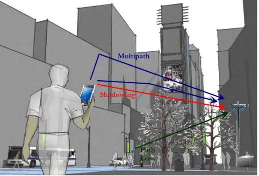
Figure 2.1. Effects of the propagation in wireless channels. ...19
Figure 2.2. Example of a typical urban propagation scenario. ...20
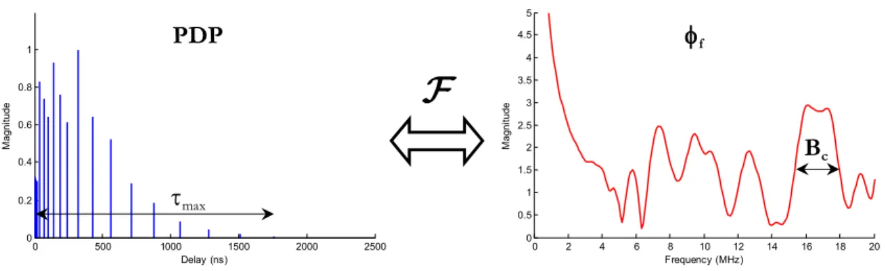
Figure 2.3. Hiperlan/2 BRAN-E PDP and frequency correlation function. ...23
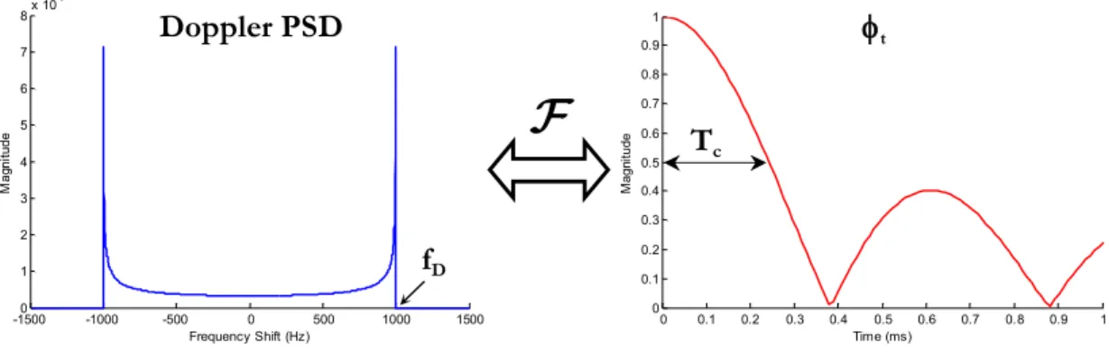
Figure 2.4. Doppler PSD and time correlation function...26
Figure 2.5. Single carrier modulation...27
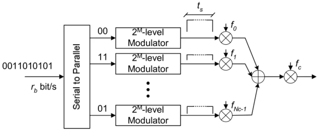
Figure 2.6. Multicarrier modulation...28
Figure 2.7. PSD of the individual OFDM sub-carriers. ...29
Figure 2.8. PSD of the OFDM signal (red – 1024 sub-carriers; blue – 8 sub-carriers). ...31
Figure 2.9. OFDM baseband transmitter model. ...31
Figure 2.10. OFDM baseband receiver model...31
Figure 2.11. Constitution of the OFDM symbol – adding the CP...32
Figure 3.1. OFDM frame structure. ...47
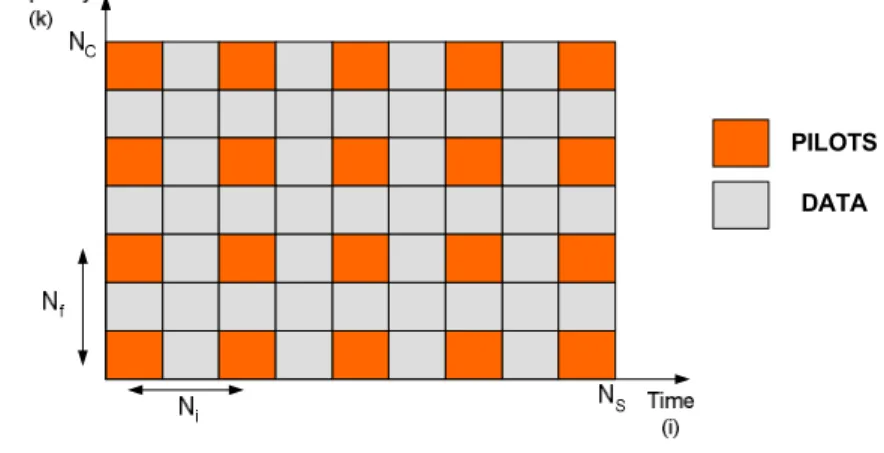
Figure 3.2. Example of rectangular pilot structure...48
Figure 3.3. Basis vectors for rectangular pilot pattern...49
Figure 3.5. Pilot-aided OFDM baseband receiver model. ...50
Figure 3.6. Ideal 2-D sinc filter. ...52
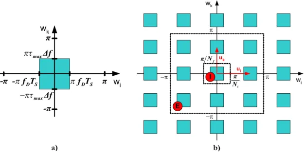
Figure 3.7. Relationship between the channel’s PSDs; a) original; b) sampled...54
Figure 3.8. Channel estimation MSE surface (BRAN-A, MT speed=10km/h, Eb/N0=0dB).58 Figure 3.9. Channel estimation MSE surface (BRAN-A, MT speed=200km/h, Eb/N0=0dB). ...59
Figure 3.10. Channel estimation MSE surface (BRAN-A, MT speed=10km/h, Eb/N0=10dB). ...59
Figure 3.11. Channel estimation MSE surface (BRAN-A, MT speed=200km/h, Eb/N0=10dB). ...59
Figure 3.12. Channel estimation MSE surface (BRAN-A, MT speed=10km/h, Eb/N0=20dB). ...60
Figure 3.13. Channel estimation MSE surface (BRAN-A, MT speed=200km/h, Eb/N0=20dB). ...60
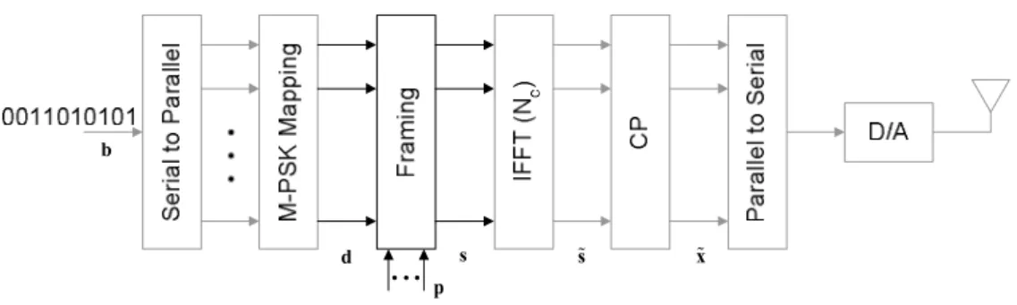
Figure 4.1. Pilot-aided OFDM baseband transmitter model...71
Figure 4.2. Pilot-aided OFDM baseband receiver model. ...71
Figure 4.3. TD pilot-aided MMSE channel estimation. ...73
Figure 4.4. Pilot-aided DFT-based channel estimation...73
Figure 4.5. Received signal for the single antenna transmitter (pilot carriers only; data sub-carriers not loaded)...74
Figure 4.6. Channel estimation MSE (indoor scenario)...82
Figure 4.7. Channel estimation MSE (outdoor scenario)...82
Figure 4.8. System BER performance (indoor scenario). ...83
Figure 4.9. System BER performance (outdoor scenario)...83
Figure 5.1 Pilot-aided MIMO-OFDM baseband transmitter model. ...94
Figure 5.2. Pilot-aided MIMO-OFDM baseband receiver model...94
Figure 5.3. Overlapping pilot scheme for OFDM systems with multiple transmit antennas....97
Figure 5.4. Decomposition of the combined received symbol (pilots only) for n =S 4 transmit antennas...100
Figure 5.5. Frequency-multiplexed pilot scheme for OFDM systems with multiple transmit
antennas...102
Figure 5.6. Symbol-multiplexed pilot scheme for OFDM systems with multiple transmit antennas...106
Figure 5.7. Comparison between real and estimated channel's frequency response. The solid line refers to the real channel while dashed line represents the estimated channel...111
Figure 5.8. Channel estimation MSE (BRAN-A indoor channel). ...111
Figure 5.9. Channel estimation MSE (BRAN-E outdoor channel)...112
Figure 5.10. MSE for STC method as a function of the number of samples used in TD window...112
Figure 5.11. System BER performance (BRAN-A indoor channel)...113
Figure 5.12. System BER performance (BRAN-E indoor channel)...114
Figure 6.1. Pilot-aided MIMO-OFDM baseband transmitter model...123
Figure 6.2. Pilot-aided MIMO-OFDM baseband receiver model. ...123
Figure 6.3. Example of the constitution of vector %g. ...130
Figure 6.4. The cost function J w
( )
...132Figure 6.5. Estimated CFO standard deviation vs. number of samples in J w
( )
...133Figure 6.6. Remaining CFO...134
Figure 6.7. Joint Channel and CFO estimation MSE (indoor channel)...135
Figure 6.8. Joint Channel and CFO estimation MSE (outdoor channel). ...135
Figure 6.9. System BER performance (indoor channel)...136
L
IST OF
T
ABLES
Table 4.1. DFT channel estimation complexity (Ops. per sub-carrier)...80 Table 4.2. Complexity comparison (Ops. per sub-carrier). ...80
L
IST OF
A
CRONYMS
0G Generation Zero mobile cellular systems
1-D One-dimensional
1G First Generation mobile cellular systems
2-D Two-dimensional
2.5G Generation 2.5 mobile cellular systems 2G Second Generation mobile cellular systems 3G Third Generation mobile cellular systems 3GPP 3rd Generation Partnership Project
4G Fourth Generation mobile cellular systems
ADC Analog-to-Digital Converter
AMC Adaptive Modulation and Coding
AMPS Advanced Mobile Phone System
ARIB/TTC Japanese Association of Radio Industries and Businesses / Telecommunication Technology Committee
AWGN Additive White Gaussian Noise
BER Bit Error Rate
BIC Bit-Interleaved Coded
BS Base Station
BWA Broadband Wireless Access
CCSA China Communications Standards Association CDMA Code Division Multiple Access
CFO Carrier Frequency Offset
CFR Channel Frequency Response
CIR Channel Impulse Response
CP Cyclic Prefix
CSD Circuit Switched Data
CSI Channel State Information
DA Data Aided
DAB Digital Audio Broadcasting
DAC Digital-to-Analog Converter
DCS1800 Digital Cellular System 1800
DFT Discrete Fourier Transform
DSSS Direct Sequence Spread Spectrum DTFT Discrete-Time Fourier Transform
DVB Digital Video Broadcasting
EDGE Enhanced Data Rates for GSM Evolution
EM Expectation-Maximization
ETSI European Telecommunications Standards Institute E-UTRA Evolved Universal Terrestrial Radio Access
FD Frequency-Domain
FDMA Frequency Division Multiple Access
GPRS General Packet Radio Service
GSM Global System for Mobile communications
HSCSD High Speed CSD
HSDPA High Speed Downlink Packet Access
HSPA High Speed Packet Access
HSUPA High Speed Uplink Packet Access ICI Inter-Carrier Interference
IDFT Inverse Discrete Fourier Transform IFFT Inverse Fast Fourier Transform
iid Independent and Identically Distributed
IMT-2000 International Mobile Telecommunications-2000
IMTS Improved MTS
IS Interim Standard
ISI Inter-Symbol Interference
ITU International Telecommunication Union JTACS Japan Total Access Communications System
LAN Local Area Network
LMS Least Mean Square
LMMSE Linear Minimum Mean Square Error
LoS Line-of-Sight
LS Least Square
LS-DFT Least Square – Discrete Fourier Transform
LTE Long Term Evolution
LTE-Advanced Advancements for Evolved Universal Terrestrial Radio Access
MAC Medium Access Control
MAI Multi-Antenna Interference
MAN Metropolitan Area Networks
MC-CDMA Multicarrier-CDMA
MIMO Multiple-Input Multiple-Output
ML Maximum Likelihood
MMSE Minimum Mean Square Error
MRC Maximum Ratio Combining
MSE Mean Square Error
MT Mobile Terminal
MTA Mobile Telephone system A
MTS Mobile Telephone System
MVU Minimum Variance Unbiased
NDA Non-Data Aided
NMT Nordic Mobile Telephone
NTT Nippon Telephone and Telegraph
OFDM Orthogonal Frequency Division Multiplexing OFDMA Orthogonal Frequency Division Multiple Access
PAN Personal Area Network
PAPR Peak-to-Average Power Ratio
PDC Personal Digital Cellular
PDF Probability Distribution Function
PDP Power Delay Profile
PHY Physical Layer
PSD Power Spectral Density
QAM Quadrature-Amplitude Modulation
QoS Quality of Service
PSK Phase-Shift Keying
RF Radio-Frequency
RLS Recursive Least Square
SISO Single-Input Single-Output
SMS Short Message Service
SNR Signal-to-Noise Ratio
STC Significant Tap Catching
TD Time-Domain
TDMA Time Division Multiple Access TS-SCDMA Time-Division Synchronous CDMA
TTA Telecommunications Technology Association
UE User Equipment
UMTS Universal Mobile Telecommunications System UTRA UMTS Terrestrial Radio Access
WAN Wide Area Network
W-CDMA Wideband CDMA
WSS Wide-Sense Stationery
L
IST OF
S
YMBOLS
( )
. i Symbol index subscript( )
( ). r Receive antenna index superscript
( )
( ),. r s Transmit antenna index to receive antenna index superscript
( )
( ). s Transmit antenna index superscript
( )
. H Hermitian transpose operator( )
. T Transpose operator{}
.E Expectation operator
data
b Number of data bits sent per symbol
c Speed of light
d Complex symbol ˆf Candidate CFO
c
d
f Doppler frequency
k
f Sub-carriers baseband frequencies
o
f Frequency offset due to the frequency mismatch of the oscillators of the transmitter and the receiver
D
f Largest magnitude Doppler frequency shift
h Channel frequency response
h% Channel impulse response i Symbol index
k FD sub-carrier index
ini
k Position of the first pilot sub-carrier
l Channel path index
m Size of the constellation
n TD sample index
R
n Number of receive antennas
S
n Number of transmit antennas
r Receive antenna index
b
r Input data rate
s
r Baud rate
s Transmit antenna index
( )
s f OFDM signal frequency response
( )
s t% Complex envelope of the OFDM signal
CP
t Duration of the CP
S
t Symbol duration (without CP)
v Mobile terminal speed
x% TD transmitted signal sample
y
ˆw Candidate angular CFO
o
w Normalized angular CFO ˆo
w Estimate of the normalized angular CFO
B System’s bandwidth
c
B Coherence bandwidth
P
D Pilot pattern density
b
E System’s energy per bit
b O
E
N System’s power efficiency
Div
G Diversity gain
H Channel frequency response (time, frequency)
( )
ˆJ w CFO cost function
( )
0 .
J Zero-order Bessel function of the first kind
L Length of guard interval
p
L Number of channel paths
sp
L Number of sub-paths in a channel path
M Number of bits per symbol
C
N Total number of sub-carriers of OFDM system (FFT size)
f
N Number of sub-carriers between consecutive pilots
i
N Number of symbols between consecutive pilots
O
N One-sided noise PSD
P
N Number of pilot sub-carriers in an OFDM symbol
S
N Number of symbols in an OFDM frame
t
N TD CIR replica separation
( )
( )
dS f Doppler PSD
h
S Channel normalized power
r
S Received signal power
St Channel power delay profile symbol
S Average symbol power
c
T Coherence time
F
T OFDM frame duration
S
T Symbol duration (with CP)
l
a Complex value of path l
f
f Channel frequency correlation function
t
f Channel time correlation function
l
a
f Time correlation of the multipath channel for the l-th path
j Angle of arrival
k Free-space phase constant
l Carrier frequency wavelength
ini
q Common phase that affects all samples of the symbol
2
Ch
s Channel power
2
e
s Channel estimation mean square error
D
f
s Spread of the Doppler PSD
[ ]
2
h l
s Average power of path l
[ ]
2
ˆh l
s Estimate of average power of path l
2
n
s Noise variance
2
ˆn
s Estimate of noise variance
2
S
N
t
s Delay spread
tl Delay of path l ˆl
t Estimate of delay of path l
max
t Channel’s maximum delay
t Average delay
f
D Sub-carrier separation
t
D System’s sampling interval
t
D Delay variation
H
F CFR correlation function
à Set of sub-carriers that convey the pilot sequences
a Set of pattern points
b Input data vector
ˆb FD column vector with estimate of the transmitted data
d FD N -complex column vector with M-ary PSK or QAM coded data C
d% TD N -complex column vector with the data symbols’ components C
present in s%
ˆd FD N -complex column vector with values received on the data sub-C
carriers
g% TD N -complex column vector with the filtered received symbol samples t
d
g% TD N -complex column vector with the data-dependent component in gt %
p
g% TD N -complex column vector with the pilot-dependent component in gt %
h FD N -complex column vector with the CFR C
h% TD N -complex column vector with the CIR C
ˆh FD N -complex column vector with the channel’s estimate C
ˆ
LS
h% TD N -complex column vector with the LS channel’s estimate t
j
(
-)
t S p
N n L –complex column vector with the samples of %g with no CIR
energy (only data-dependent and noise)
n FD N -complex column vector with noise values C
n% TD N -complex column vector with noise samples C
n% TD
(
NC +L -complex column vector with noise samples)
p FD N -complex column vector with pilot values C
p% TD N -complex column vector with pilot symbols’ components present in C
s%
r FD N -complex column vector with the received symbol values C
r
% TD N -complex column vector with the received symbol samples (without C
CP)
c
r% TD N -complex column vector with the received symbol samples after C
CFO correction
d
r% TD N -complex column vector with the data-dependent component in C %r
p
r
% TD N -complex column vector with the pilot-dependent component in C %r
s FD N -complex column vector with transmitted signal C
s
% TD N -complex column vector with transmitted signal (without CP) C
%t TD rectangular low-pass window vector
i
u Channel’s PSD replicas placement (symbol dimension) basis column vector
k
u Channel’s PSD replicas placement (frequency dimension) basis column vector
v FD N -complex column vector with filtered noise samples t
v% TD N -complex column vector with filtered noise samples t
i
v Symbol dimension pilot pattern basis column vector
k
x% TD
(
NC+L)
-complex column vector with transmitted signal (with CP)y% TD
(
+)
C
N L -complex column vector with the symbol samples (with CP)
z% TD
(
NC+L -complex column vector with the ISI samples that affect the)
symbol CP A
(
NC +L)
´NC CP adding matrix( )
C N woC NC´N diagonal matrix with the phase rotations that affects the symbol C
samples
F NC´N DFT matrix C
H FD NC´NS channel frequency response matrix (frame)
circ
H% TD NC´N circulant matrix with circulant vector h% C
lin
H% TD
(
NC +L) (
´ NC +L lower triangular Toeplitz channel convolution)
matrix with first column h% ˆ
LS
H FD NC´NS matrix with sampled LS channel’s estimate
' ˆ LS H FD C S f i N N
N ´ N matrix with LS channel’s estimate
C N I NC´N identity matrix C , C N L I C
N ´ matrix with the L last columns of L I NC
N FD NC´NS matrix with noise values
S
N FD NC´NS matrix with sampled noise values
Q FD NC´N channel frequency response diagonal matrix C
CP
R NC´
(
NC +L)
CP removing matrixhh
R%% TD
(
´)
t t
N N channel correlation matrix
ˆ
hh
R%% TD
(
Nt´N filter input–output cross-correlation matrix t)
ˆ ˆ
hh
S FD NC´NS matrix with transmitted signal
T Nt´N matrix with TD pilot sub-carriers selection (multi-band) filter C
U 2 2´ channel’s PSD replicas placement basis matrix
V 2 2´ pilot pattern basis matrix
W 2-D estimation filter matrix
e
W Error filter matrix
MMSE
W% TD NC´N LMMSE filter C
P
W Ideal 2-D sinc filter matrix
C
N ´L
0 NC´ null matrix L
[ ]
d k FD data vector d k-th element
[ ]
d n% TD data vector d% n-th element
[ ]
g n% TD filtered vector g% n-th sample
[ ]
d
g n
% TD data-dependent filtered vector g% n-th sample d
[ ]
p
g n
% TD pilot-dependent filtered vector g% n-th sample p
[ ]
h k Channel frequency response vector h k-th element
[ ]
h n% Discrete-time channel impulse response vector h% n-th element
[ ]
n n% TD noise vector n% n-th sample of iid zero mean AWGN with variance s2
n
[ ]
n n% TD noise vector n% n-th sample of iid zero mean AWGN with variance s2
n
[ ]
p k FD pilot vector p k-th element
[ ]
p n% TD pilot vector p% n-th element
[ ]
r n% TD received vector r% n-th signal sample
[ ]
p
r n% TD received pilot-dependent vector r% n-th signal sample p
[ ]
s k FD transmitted signal vector s k-th element
[ ]
[ ]
t n% TD rectangular low-pass window %t n-th element
[ ]
u n Unit-step function
[ ]
v k FD filtered noise vector v k-th sample
[ ]
v n% TD filtered noise vector v% n-th sample
[ ]
y n% TD received vector y% n-th signal sample
[ ]
,E k i Estimation error of the k-th sub-carrier of the i-th symbol
[ ]
,H k i FD channel frequency response matrix
( )
k i -th element ,[ ]
ˆ ,
H k i FD channel frequency response estimate
( )
k i -th element ,[ ]
ˆ ,
LS
H k i FD LS channel’s estimate matrix
( )
k i -th element ,[ ]
'
ˆ ,
LS
H k i FD sampled LS channel’s estimate matrix
( )
k i -th element ,[ ]
,S
H k i FD sampled channel frequency response
( )
k i -th element ,[ ]
,N k i FD noise matrix
( )
k i -th element ,[ ]
,S
N k i FD sampled noise matrix
( )
k i -th element ,[ ]
,S k i FD transmitted signal matrix
( )
k i -th element ,(
,)
H k i
S w w Channel’s power spectral density
(
w w -th element k, i)
(
,)
S
H k i
S w w Sampled channel’s power spectral density
(
w w -th element k, i)
[ ]
,W k i 2-D estimation filter
( )
k i -th element ,[ ]
,e
W k i Error filter
( )
k i -th element ,[ ]
,P
CHAPTER 1
I
NTRODUCTION
I
NTRODUCTION
In this chapter we present a brief historic evolution of the wireless cellular systems leading to the adoption of multicarrier modulations schemes in the most recent standards. We then emphasize the importance of the multicarrier wireless system’s operations addressed in this thesis: channel estimation and carrier frequency offset estimation, as a motivation to this work and present the thesis statement. The main contributions resulting of this thesis are identified, followed by an overview of the structure of this document.
Channel and Frequency Offset Estimation Schemes for Multicarrier Systems
1.1. Evolution of Cellular Systems
The appearance of wireless communications over a century ago changed the society we live in. Its origin can be traced back to 1886, when Hertz generated for the first time electromagnetic waves, thus proving the equations by Maxwell that predicted its existence two decades before [Mah03]. The work of Marconi in the following years showed the world the potential of this new discovery, culminating in 1901 with first transatlantic radio communication. The 1920s witness the beginning of regular radio broadcasting services. In 1940 the first two-way radio, the “Handie-Talkie” SCR536, was presented by Motorola [Mot09] and in 1946 the Bell System introduced in St. Louis one of the earliest mobile telephone standards in the USA, the Mobile Telephone System (MTS). It was a half-duplex system, where the operator assisted the user to place or route the call in both directions. An improved full-duplex version of this system, the Improved MTS (IMTS), offering direct-dial and caller identification, was only released in 1964. Meanwhile, Ericsson developed the first fully automatic phone system, the Mobile Telephone system A (MTA) [Bil06], and made the first trials in Sweden in 1956. The base stations were fully automatic and the client’s equipment weighed around 40Kg.
In the context of mobile cellular systems, each generation of systems is characterized by a concept and/or technologic leap from the previous. Some authors consider these early pre-cellular systems to constitute the generation zero (0G) of the mobile cellular systems. The first generation (1G) of mobile cellular systems breakthrough was the use of the concept of cellular network. The cellular concept for mobile wireless systems was proposed by Bell Labs engineer D. H. Ring in his 1947 technical memorandum [Rin47]. The main idea behind this concept is the reuse of the available spectrum, by dividing the geographical area to be covered by the system in adjacent non-overlapping hexagonal-shaped cells. Unlike 0G system, where a single powerful transmitter covered all area and used all available frequency channels, the new generation systems would have low-power transceivers, the Base Station (BS), in each cell, using only a subset of all available channels. By doing so, BSs in non-adjacent cells could reuse the channels with little interference and greatly increase the overall number of channels available for the system’s users.
The cellular technology and the required electronics were mainly developed at Bell Labs until the 1970s [CEUC97], and the first commercial systems saw the light of day in the early 80s. A wealth of systems rapidly spread in different countries. Ericsson claims that its Nordic Mobile Telephone (NMT) was the first truly mobile cellular system to be deployed in Scandinavian countries in 1981. This system was also adopted by Switzerland, Netherlands and some Eastern Europe countries. Shortly afterward, in 1984, the Bell Labs’ Advanced
Chapter 1 – Introduction
Mobile Phone System (AMPS) initiated its operation in the USA and was later adopted in Australia. In 1985, the Total Access Communication System was inaugurated in Great Britain. Germany and Portugal adopted the C-450 system. In Japan, multiple systems were developed and deployed. The Nippon Telephone and Telegraph (NTT) developed and deployed three standards: TZ-801, TZ-802, and TZ-803, and the competitor DDI used the Japan Total Access Communications System (JTACS) [Pad95], [Rap96], [Stu96].
The 1G systems shared some important characteristics like analog frequency modulation for voice transmission, digital signalling, handover and the separation of the channels by allocation of different non-overlapping frequency bands, called frequency division multiple access (FDMA) [Pro01]. These systems suffer from the important drawback of being incompatible among each other. Its capacity was quickly exhausted with the rapid increase in the number of users and the quality of service provided was far from satisfying the customers.
The advances in the area of micro-electronics, with an ever increasing rate of integration, leading to the introduction of the microprocessor in the 70’s and the development of efficient digital signal processing techniques, like digital speech coders, channel coders for error protection and encryption algorithms for improved security and privacy, supported the birth of the second generation (2G) mobile cellular systems [Pad95], the first fully digital cellular generation. Presenting significant improvements in quality of service and availability for customers, and increased spectral efficiency, smaller, more reliable, less power-hungry BSs and overall cheaper provider structure, the 90’s witness the burst of digital personal wireless communications [CEUC97]. The majority of the 2G systems used time division multiple access (TDMA) schemes [Pro01] to separate the channels of the different users. The ubiquitous Global System for Mobile communications (GSM) is one such system, making its debut in Europe and spreading to most continents in over 100 countries. Other examples of successful 2G TDMA systems are the Digital Cellular System 1800 (DCS1800) present in Europe, the Interim Standard (IS) 54 in the USA and the Personal Digital Cellular (PDC) system in Japan, just to name a few [Rap96], [Stu96].
Stemming from the military secure communications systems of the first half on the 20th century [Sch82], commercial 2G systems using code division multiple access (CDMA)
with direct sequence spread spectrum (DSSS) [Pro01] were developed and deployed with considerable success [Rap96], [Stu96]. Characterized by using a bandwidth much greater than the minimum required for a single user [Dix94], the information from the users is separated in the code domain, by the use of independent spreading codes. Of this group, the USA IS-95 system stands out as the most successful one.
The 2G systems were developed as cellular systems for the transmission of voice. Services other than voice calls (Facsimile, Short Message Service (SMS) and other low data
Channel and Frequency Offset Estimation Schemes for Multicarrier Systems
switched nature of the system kept unchanged. The extraordinary growth of Internet users in the 90’s was seen as a promising new breath for the wireless cellular systems that would provide Internet access anywhere with the plus of adding mobility.
The original 2G systems fell short in handling packet-oriented services required by Internet access. The most severe limitations were the limited bandwidth and its circuit switched nature. To overcome the limited bandwidth, higher data rate evolutions were introduced. Still in 20th century, Circuit Switched Data (CSD) and High Speed CSD (HSCSD)
services promise speeds of up to 57,6 kbit/s, when aggregating 4 GSM time slots. In the early 21st century, the General Packet Radio Service (GPRS) offered up to 115 kbit/s and the
Enhanced Data Rates for GSM Evolution (EDGE) service claimed the figure of 384 kbit/s. These added services, that came to be known as generation 2.5 (2.5G), pave the way for the third generation (3G) of wireless cellular systems. The motivation behind the development of this generation was to offer a wireless system that supported a wide range of services, advertised with the slogan “Anywhere, Anything, Anytime”. The traditional low bitrate voice calls with be offered along high bandwidth demanding multimedia services like video-calls and video related applications, high speed Internet surfing, online gaming, etc.
These new services should be available in indoor and outdoor scenarios, with high mobility, variable and asymmetric bitrates, different quality of service (QoS) demands, while providing a smooth transition from the previous generation systems.
The development of the 3G systems started in the late 80’s under the guidance of several standardization bodies. The European Telecommunications Standards Institute (ETSI) was involved in the collaborative 3rd Generation Partnership Project (3GPP) [3GPP], along
with the Japanese Association of Radio Industries and Businesses/Telecommunication Technology Committee (ARIB/TTC), the China Communications Standards Association (CCSA), the North American Alliance for Telecommunications Industry Solutions (ATIS) and South Korean Telecommunications Technology Association (TTA), from what emerged the first Universal Mobile Telecommunications System (UMTS) standard in 1998 [ETS98] defining the Wideband CDMA-based (W-CDMA) UMTS Terrestrial Radio Access (UTRA). This is the 3G standard currently adopted and deployed throughout Europe.
The European UMTS standard together with a number of other 3G standards, like the North American CDMA2000 and the Chinese Time-Division Synchronous CDMA (TS-SCDMA), form the International Mobile Telecommunications-2000 (IMT-2000) family of standards, defined by the International Telecommunication Union (ITU) with the intent of facilitating the growth of 3G systems worldwide. Though several radio interfaces are defined in the several standards making up IMT-2000, the major technological breakthroughs of the
Chapter 1 – Introduction
3G systems are the adoption of CDMA, Turbo Coding and Multiple-Input Multiple-Output (MIMO) techniques [Lu02], [Pra01].
The growth of bandwidth demanding multimedia services continued at a fast pace and the 3G systems kept evolving to satisfy the demands of customers. In 2002, the 3GPP Release 5 standard defined the enhanced 3G packet-oriented full-IP radio interface High Speed Downlink Packet Access (HSDPA) [Par06] which allows UMTS-based systems to reach downlink rates of up to 14,0Mbit/s. The 2004 3GPP Release 6 standard defined the uplink counterpart High Speed Uplink Packet Access (HSUPA) for increased uplinks rates of up to 5,8Mbit/s. Collectively these two new radio access schemes form the High Speed Packet Access (HSPA) that is being widely adopted by operators all over the world. The 2008 Release 8 provided a further rate increase with HSPA+, promising speeds of up 42Mbit/s in the downlink and 11Mbit/s in the uplink, with the adoption of MIMO capability and high-order modulations (64 levels Quadrature-Amplitude Modulation (QAM) in the downlink and 16-QAM in the uplink).
The HSPA standards represent a smooth evolution of the deployed UMTS networks, maintaining most of the structure and sometimes implemented as a software upgrade for both customers and providers. Building on the success of Orthogonal Frequency Division Multiplexing (OFDM)-based local area network (LAN) and wide area network (WAN) standards like IEEE 802.11a/g [802.11a], [802.11g] and 802.16 [802.16], the 3GPP has been involved in the parallel development of the OFDM-based Long Term Evolution (LTE) specification, a strong candidate has the underlying technology for the 4th generation (4G)
wireless cellular systems, technologically incompatible with the current CDMA-based 3G standards.
The LTE specifications were introduced by the 3GGP Release 8 standard in 2008. The demands on the new standard are remarkable:
· Widest range of services from telephony to real-time high-definition video, mobile TV or high speed Internet surfing, and flexibility to accommodate future bandwidth-demanding applications;
· Interconnection and interoperability with different wireless and wired systems; · Interaction with users to simplify the introduction of new applications and
business models;
· Flexible spectrum utilization; · High spectral efficiency;
Channel and Frequency Offset Estimation Schemes for Multicarrier Systems
· High mobility scenarios;
· Variable and on-demand bitrates; · Highly asymmetric bitrates;
To meet the goals, the LTE new radio interface Evolved Universal Terrestrial Radio Access (E-UTRA) is defined [LTE]. Some of its most significant specifications are:
· OFDM-based modulations for both downlink (Orthogonal Frequency Division Multiple Access – OFDMA) and uplink (Single Carrier Frequency Division Multiple Access – SC-FDMA);
· Adaptive Modulation and Coding (AMC) with up to 64-QAM and turbo coding;
· Single user and multi-user MIMO with up to four antennas per station; · Flexible bandwidth from 1,25 MHz to 20 MHz;
· Peak bitrates of 326,4Mbit/s for MIMO 4x4 and 172,8Mbit/s for MIMO 2x2 for every 20 MHz of bandwidth, increasing the spectral efficiency 2 to 4 times when compared with HSPA;
The current LTE Release 8 still fells short of the ITU targeted peak bitrate of 1Gbit/s to fully support the 4G requirements [ITU1645] and the LTE-Advanced standard is currently in development and it is expected that will represent a backward compatible enhancement of current LTE standard [LTEadv]. The 3GPP Release 10 standard will define its specifications and it should be final in 2010. Some key topics that it should address are the use of wider bandwidths by spectrum aggregation, improved MIMO techniques to increase bitrates, use of relaying techniques to increase throughput and coverage and coordinated multipoint transmission/reception [Par08].
1.2. Thesis Statement
The OFDM-based broadband wireless systems are emerging in distinct services. In broadcasting it can be found in the European standards for Digital Audio Broadcasting (DAB) [DAB] and in the terrestrial Digital Video Broadcasting (DVB) [DVB-T]. In the wireless LAN environment is used daily by millions of people connecting to their networks with IEEE 802.11a [802.11a] and IEEE 802.11g [802.11g] wireless cards. In the wireless metropolitan area networks (MAN), Broadband Wireless Access (BWA) systems, commercially termed “WiMAX” and defined in IEEE 802.16 standard [802.16], are currently being installed all over
Chapter 1 – Introduction
the world and the trends for future 4G systems [LTEadv] point for the adoption of OFDM-based radio interfaces.
The transmission over multipath wireless channels has a severe impact on the system’s performance. The received signal is attenuated, distorted and delayed. A detailed description of these impairments is introduced in the next chapter. Noise, interference and system’s imperfection also negatively impacts the system’s performance.
To fully explore the potential of OFDM modulation, the system must mitigate these negative effects. Firstly, the receiver needs to recover the synchronization of the received signal. The use of multiple sub-carriers makes OFDM systems highly susceptible to synchronization errors [Pol95], [Pol95a] and the ability of the receiver to mitigate these errors is of paramount importance for the system’s performance [Moo94], [Wan03], [Rug05], [Kro08].
The synchronization entails three distinct tasks: symbol timing synchronization, sampling frequency synchronization and carrier frequency offset (CFO) correction [Ai06]. The symbol timing synchronization is the process of determining the correct symbol starting position. The sampling frequency synchronization goal is to mitigate the misalignment of the samples of the received signal, due to the mismatch of the crystal oscillators of the transmitter digital-to-analog converter (DAC) and the receiver analog-to-digital converter (ADC). The CFO correction aims at reducing the frequency offset present in the received signal, caused by the frequency mismatch between the local oscillators of the transmitter and the receiver.
Once synchronization is achieved, or in a joint process, the effect of the channel on the received signal must be estimated. This operation is also of major relevance for the system. The channel estimate will be used throughout the system for coherent detection [Pro01], AMC [Kee06], MIMO techniques [Ges03], pre-equalization [Sil04], interference cancellation [Ver98], mobile terminal (MT) positioning [TS36.305] and cross-layer design [Lau06].
The importance of channel estimation is well-known and studied. In [Pro01] a closed formula is given for the bit error rate (BER) performance as a function of the correlation between the channel and its estimate, when transmitting over a multipath channel and using 4 Phase-Shift Keying (QPSK) modulation with coherent Maximum Ratio Combining (MRC) detection. This analysis clearly shows the impact of the multipath channel and of the channel estimator in the system’s performance.
The recent standards for wireless systems define the use of high order modulations and extended service coverage, thus forcing the receivers to operate at very low signal-to-noise ratio (SNR) regimes. The synchronization algorithms must achieve a near perfect performance and the channel estimation scheme must output a very accurate estimate, while keeping the complexity to a minimum to maintain the MT portability, low cost and battery life.
Channel and Frequency Offset Estimation Schemes for Multicarrier Systems
A considerable body of work can be found in the literature and research actively continues on the topics of synchronization and channel estimated for OFDM-based systems.
This thesis addresses the topics of channel estimation and CFO estimation for OFDM-based systems with multiple antennas at both ends of the link. It aims at contributing with original low complexity algorithms with a performance that meets the requirements of the recent and near future wireless cellular standards.
This thesis states that the careful design and placement of the pilot sequences, together with the exploitation of properties of the DFT, allow the design and implementation of reduced complexity cooperating channel and CFO estimation algorithms that exhibit good performance when compared with the reference algorithms in the literature.
1.3. Contributions of this Thesis
The work developed in this thesis was partially supported by the European projects “WISQUAS - WIreless Systems providing high QUAlity Services” [WIS05], “Network of Excellence ACE - Antenna Centre of Excellence” [ACE06], “CRUISE - CReating Ubiquitous Intelligent Sensing Environments” [CRU06], “CODIV – Enhanced Wireless Communication Systems Employing COoperative DIVersity” [COD08], and the National projects “FFT-XXI – FFT-based solutions for the wireless communications of the XXIst century” [FFT05] and “PHOTON – Distributed and Extendible Heterogeneous Radio Architectures using Fibre Optic Networks” [PHO07] and the original contributions were disseminated in the publications listed in Section 1.3.1. It can be synthesized in the following:
· The analytical formulation of the channel estimation mean square error (MSE) for the single-user OFDM downlink scenario with a generic channel estimation scheme for a given power efficiency;
· A pilot-aided minimum MSE (MMSE) channel estimation scheme for broadband OFDM systems is developed. The careful placement of the pilots in the OFDM symbol leads to the proposal of a simplified time-domain (TD) MMSE estimator that explores the Fourier properties of the pilot and data- carrying symbols to extract the MMSE channel impulse response (CIR) estimate from the TD received symbol samples. Using the knowledge that the CIR energy is mainly limit to a small set of samples, a method to estimate the filter parameters is introduced.
· A pilot-aided channel estimation scheme for broadband MIMO OFDM systems is proposed. By constraining the placement of the orthogonal
phase-Chapter 1 – Introduction
shifted pilot sequences and exploring the properties of the DFT, the investigated algorithm extracts the CIRs in the TD for all channels involved in the transmission process. The investigated pilot sequences allow the separation of the CIRs for the different channels from the data components when the symbols are transmitted over Rayleigh fading multipath channels and are robust against co-channel interference.
· A CFO estimation algorithm and associated channel estimation method for broadband OFDM systems with transmitter diversity is proposed. The investigated CFO estimation algorithm explores the TD structure of the transmitted symbols carrying pilots and data. Avoiding additional overhead, like training symbols or null sub-carriers, and relying solely on the data component present on those symbols, the investigated CFO algorithm outputs a highly accurate estimate. An intermediate output of the algorithm is used as input to the TD MMSE filter used in the investigated channel estimation scheme, resulting in a low complexity joint block with no performance trade-off.
1.3.1 Dissemination of original contributions
The original contributions presented in this thesis were disseminated in the following scientific publications.
Scientific Journals with Referees:
[Rib09] C. Ribeiro, A. Gameiro, “Estimation of CFO and Channels in Phase-Shift Orthogonal Pilot-Aided OFDM Systems with Transmitter Diversity,” EURASIP
Journal on Wireless Communications and Networking, vol. 2009, no. 1, pp. 1 – 10, January
2009.
[Rib08a] C. Ribeiro, M. J. Garcia, V. Jiménez, A. Gameiro, A. Armada, “Uplink channel estimation for multi-user OFDM-based systems,” Wireless Personal Communications, vol. 47, no. 1, pp. 125 – 136, October 2008.
[Rib08b] C. Ribeiro, A. Gameiro, “An OFDM Symbol Design for Reduced Complexity MMSE Channel Estimation,” Journal of Communications, vol. 3, no. 4, pp. 26 – 33, September 2008.
Channel and Frequency Offset Estimation Schemes for Multicarrier Systems
Scientific Conferences with referees:
[Nev09] D. Neves, C. Ribeiro, A. Silva, A. Gameiro, “Channel Estimation Schemes for OFDM Relay-Assisted Systems,” in Proc. IEEE Vehicular Technology Conference, Barcelona, Spain, April 2009.
[Rib08c] C. Ribeiro, A. Gameiro, “Mitigating CFO in OFDM systems by exploring the symbol's structure,” in Proc. IEEE International Symposium on Wireless Communication
Systems, Reykjavik, Iceland, October 2008.
[Rib08d] C. Ribeiro, A. Gameiro, “MIMO-OFDM Channel Estimation – a Pilot Sequence Design for Time-domain Processing,” in Proc. International Conference on Wireless
Information Networks and Systems, Oporto, Portugal, July 2008.
[Rib07a] C. Ribeiro, A. Gameiro, “On the impact of the pilot density in the channel estimation of MC-CDMA systems,” in Proc. IEEE International Symposium on
Wireless Communication Systems, Trondheim, Norway, October 2007.
[Rib07b] C. Ribeiro, A. Gameiro, “Direct time-domain channel impulse response estimation for OFDM-based systems,” in Proc. IEEE Vehicular Technology Conference, Baltimore, USA, September 2007.
[Rib07c] C. Ribeiro, A. Gameiro, “Uplink time-domain MMSE channel estimation for MC-CDMA systems,” in Proc. IEEE International Symposium on Personal, Indoor and Mobile
Radio Communications, Athens, Greece, September 2007.
[Rib07d] C. Ribeiro, A. Gameiro, “2D Wiener channel estimation performance analysis with diamond-shaped pilot-symbol pattern in MC-CDMA systems,” in Proc. Conference
on Telecommunications, Peniche, Portugal, May 2007.
[Rib07e] C. Ribeiro, M. J. Garcia, V. Jiménez, A. Gameiro, A. Armada, “Uplink channel estimation for multi-user OFDM-based systems,” in Proc. COST 289 Workshop on
Spectrum and Power Efficient Broadband Communications, Gothenburg, Sweden, April
2007.
1.4. Thesis Organization
This thesis is made-up of seven chapters with similar structure. With the exception of last chapter, each has its own abstract, state-of-the-art and references section. The rationale beyond this structure is to ease the reading of the document, as the reader can easily identify the chapter(s) of interest to his work.
Chapter 2 presents an overview of the wireless multipath channel and its modelling, and the DFT-based multicarrier transmission systems. The wireless multipath channel review focus on the wide-sense stationary uncorrelated scattering (WSSUS) channel model that will
Chapter 1 – Introduction
be used throughout this thesis. The expressions of the multipath channel that are relevant for the following chapters are introduced. Some channel characterization measurements, like coherence bandwidth and coherence time, are given. A brief historical overview of multicarrier systems focusing on OFDM systems follows. The chapter ends with the basic working principles of OFDM and a detailed analysis of the signal flow from origin to destination, with emphasis on the role played by the wireless channel and how the OFDM deals with time dispersive nature of the multipath channel.
The impact of the pilot density in the performance of the channel estimation for OFDM systems is investigated in Chapter 3,. The analytical formulation of the channel estimation MSE for the single-user downlink scenario with a generic channel estimation scheme for a given power efficiency is given. The chapter ends with a set of system simulations that validate the analytical formulation.
Chapter 4 revisits the MMSE pilot-aided channel estimation for broadband OFDM systems. The careful design of the OFDM symbol leads to the proposal of a simplified TD MMSE estimator that explores the Fourier properties of the pilot and data- carrying symbols to extract the CIR from the TD received symbol samples and directly input it to the MMSE filter. Additionally, by using the knowledge that the CIR energy is mainly limit to a small set of samples, a simple, yet efficient, estimation of the filter parameters is introduced. Indoor and outdoor simulation results show that the performance of the investigated channel estimation scheme presents a tolerable degradation when compared with the a-priori knowledge of the channel correlation and noise variance, while exhibiting a reduced computational load.
In chapter 5, a channel estimation scheme for broadband MIMO OFDM systems is proposed. The design of the pilot sequences to explore the properties of the DFT opened way to the extraction of the CIRs in the TD for all channels involved in the transmission process. The investigated pilot sequences allow the separation of the CIRs for the different channels from the data components when the symbols are transmitted over Rayleigh fading multipath channels and are robust against co-channel interference. The feasibility of the investigated scheme is substantiated by system simulations.
Chapter 6 presents a CFO estimation algorithm and an associated channel estimation method for broadband OFDM systems with transmitter diversity. The investigated CFO estimation algorithm explores the TD structure of the transmitted symbols carrying pilots and data. Relying solely on the data component present on those symbols, it estimates the CFO with high accuracy, avoiding additional overhead like training symbols or null sub-carriers. An intermediate output of the CFO algorithm provides an easy to get initial CIR estimate that will be improved with the utilization of a TD MMSE filter. Indoor and outdoor system simulations show that the joint algorithms result in a near optimal system’s performance.
Channel and Frequency Offset Estimation Schemes for Multicarrier Systems
The last chapter starts with a brief introduction to the demands that the future cellular wireless systems will have to fulfil to fully support the 4G requirements, and to some of the most challenging issues affecting the OFDM-based systems. The topics of research addressed in this thesis are identified and the main conclusions that come out of this work drawn. The major contributions resulting from this thesis are related to the main conclusions and, finally, the directions for future research work are identified.
1.5. References
[3GPP] Third Generation Partnership Project, http://www.3gpp.org.
[802.11a] IEEE Std. 802.11a-1999, “Local and metropolitan area networks – Specific requirements – Part 11: Wireless MAC and PHY specifications – High-speed physical layer in the 5 GHz band,” Sept. 1999.
[802.11g] IEEE Std. 802.11g-2003, “Local and metropolitan area networks – Specific requirements – Part 11: Wireless LAN medium access control (MAC) and physical layer (PHY) specifications – Amendment 4: Further higher data rate extension in the 2.4 GHz band,” June 2003.
[802.16] IEEE Std. 802.16-2009, “Local and metropolitan area networks – Part 16: Air interface for broadband wireless access systems,” May 2009.
[ACE06] Network of Excellence ACE – Antenna Centre of Excellence, http://www.ist-ace.org/, 2006.
[Ai06] B. Ai, C. Pan, J. Ge, Y. Wang, Z. Lu, “On the synchronization techniques for wireless OFDM systems,” IEEE Transactions on Broadcasting, vol. 52, no. 2, pp. 236 – 244, June 2006.
[Bil06] O. Billström, L. Cederquist, M. Ewerbring, G. Sandegren, J. Uddenfeldt, “Fifty years with mobile phones: From novelty to no. 1 consumer product,”
www.ericsson.com/ericsson/corpinfo/publications/review/2006_03/files/3_fifty _years.pdf, 2006.
[CEUC97] Committee on Evolution of Untethered Communications, National Research Council, The Evolution of Untethered Communications, Washington D.C., USA, National Academy Press, 1997.
[COD08] CODIV – Enhanced Wireless Communication Systems Employing COoperative DIVersity, http://www.ict-codiv.eu/, 2008.
[CRU06] CRUISE - CReating Ubiquitous Intelligent Sensing Environments, http://www.ist-cruise.eu/, 2006.
Chapter 1 – Introduction
[DAB] ETSI Std. ETS 300 401 v1.4.1, “Radio broadcasting systems; Digital audio broadcasting (DAB) to mobile, portable and fixed receivers,” June 2006.
[Dix94] R. Dixon, Spread Spectrum Systems with Commercial Applications, New York, USA, John Wiley & Sons, 1994.
[DVB-T] ETSI Std. ETS 300 744 v1.6.1, “Digital video broadcasting (DVB); Framing structure, channel coding and modulation for digital terrestrial television,” Jan. 2009.
[ETS98] ETSI SMG Tdoc 032/98, “Proposal for a Consensus Decision on UTRA,” 1998. [FFT05] FFT-XXI – FFT-based solutions for the wireless communications of the XXIst
century, http://www.av.it.pt/motion/projects_4.htm, 2005.
[Ges03] D. Gesbert, M. Shafi, D. Shiu, P. Smith, A. Naguib, “From theory to practice: An overview of MIMO space–time coded wireless systems,” IEEE Journal on Selected
Areas in Communications, vol. 21, no. 3, pp. 281–302, April 2003.
[ITU1645] ITU-R Recommendation M.1645, “Framework and overall objectives of the future development of IMT-2000 and systems beyond IMT-2000,” June 2003.
[Kee06] S. Kee-Bong, A. Ekbal, C. Taek, J. Cioffi, “Adaptive modulation and coding (AMC) for bit-interleaved coded OFDM (BIC-OFDM),” IEEE Transactions on
Wireless Communications, vol. 5, no. 7, pp. 1685 – 1694, July 2006.
[Kro08] M. Krondorf, G. Fettweis, “OFDM Link Performance Analysis under Various Receiver Impairments,” EURASIP Journal on Wireless Communications and Networking, vol. 2008, pp. 1 – 11, January 2008.
[Lau06] V. Lau, Y. Kwok, Channel-Adaptive Technologies and Cross-Layer Designs for Wireless
Systems with Multiple Antennas: Theory and Applications, Hoboken, New Jersey, USA,
John Wiley & Sons, 2006.
[LTE] ETSI Technical Specification TS 136 201 v8.3.0, “LTE; Evolved universal terrestrial radio access (E-UTRA); Long Term Evolution (LTE) physical layer; General description,” April 2009.
[LTEadv] ETSI Technical Report 136 913 V8.0.1, “LTE; Requirements for further advancements for Evolved Universal Terrestrial Radio Access (E-UTRA) (LTE-Advanced),” April 2009.
[Lu02] W. Lu, Broadband Wireless Mobile: 3G and Beyond, Chichester, England, John Wiley & Sons, 2002.
[Mah03] B. Mahon, The Man Who Changed Everything: The Life of James Clerk Maxwell, Chichester, England, John Wiley & Sons, 2003.