Vol. 34, No. 03, pp. 789 – 798, July – September, 2017 dx.doi.org/10.1590/0104-6632.20170343s20150452
* To whom correspondence should be addressed
EVALUATION OF MASS TRANSFER IN A NOVEL
HOLLOW FIBER MODULE DESIGN USING AN
ELECTROCHEMICAL TECHNIQUE
L. S. de França Neta
1*, C. P. Borges
2and A. C. Habert
21Centro Federal de Educação Tecnológica de Minas Gerais, CEFET-MG, Av. Amazonas 5253. Sala 401. Nova Suiça,
30421-169 Belo Horizonte, MG, Brasil.
*Email: [email protected]; Phone: +55 31 3319-7151
2Programa de Engenharia Química, COPPE – Universidade Federal do Rio de Janeiro, 21945-970, Rio de Janeiro, RJ, Brasil.
Phone: +(55) (21) 2562-7169, Fax: +(55) (21) 2562-8300
(Submitted: July 16, 2015; Revised: February 25, 2016; Accepted: April 24, 2016)
Abstract – The mass transfer coefficient (KL) determined using an electrochemical technique was used
in this work as a parameter to evaluate the hydrodynamics of hollow fiber membrane modules. A new microfiltration module configuration was investigated, taking advantage of the hydrocyclone concept aimed at reducing the concentration of the polarization layer near the membrane surface promoted by the centrifugal field. The mass transfer coefficient for the new configuration was compared with that of a conventional longitudinal module. The experimental determination of KL was obtained by monitoring the electrochemical reactions that occur at the electrode surface under mass transfer-limiting conditions. The performance of the microfiltration modules, both hybrid and longitudinal, was evaluated based on parameters such as packing density and fluid flow regimes. The results achieved for the mass transfer coefficient with the electrochemical technique allowed for performance evaluations of the proposed new module configuration and a comparison with the longitudinal module.
Keywords: Electrochemical method, mass transfer coefficient, hollow fiber, permeation module.
INTRODUCTION
MSPs (membrane separation processes) have been used in several industrial sectors, such as in the chemical, food, pharmaceutical, medical and biotechnological fields. The global market for microfiltration (MF) liquid and gas separation is projected to increase from $1.6 billion in 2014 to approximately $2.6 billion in 2018 for a compound annual growth rate of 10.0% (BCC Research, 2013). The
microfiltration process (MF) was among the first to be implemented on an industrial scale.
A new breakthrough in MF is dependent on the control of the permeate flux decline due to the concentration polarization and, mainly, fouling development. The former refers to the concentration gradient of the rejected species that occurs near the membrane surface. The latter is intensified by concentration polarization, and it is associated with several processes that help increase the
of Chemical
L. S. de França Neta, C. P. Borges and A. C. Habert 790
transport resistance for permeation, such as pore blocking, precipitation and cake formation by particle deposition or gelation formation on the membrane surface (Davis, 1992, Mulder, 1996, Strathmann, 2001, Ripperger, 2002).
These limiting factors are results of hydrodynamic restrictions imposed by the permeation module design. For the microfiltration process, for instance, it has been shown that only an integrated approach considering the membrane development, with high surface porosity and strong hydrophilic character for the permeation module geometry and the operational plant strategies, can lead to a high performance process (Van der Horst, 1990).
The development of permeation modules in the 1960s and 1970s was first based on conventional filtration technology and earlier design was based on the conventional filtration technology, with modules very similar to the plate-and-frame filter press packed with flat sheet membrane. Very rapidly, tubular, spiral-wound and hollow fiber membrane modules emerged. The market acceptance of these configurations was related to the operational and production costs (Baker, 2012).
New designs of modules were attempted with the aim of reducing the concentration polarization in order to improve the hydrodynamics inside the module, trying to induce secondary flows and Dean vortex turbulence promoters (Brewster et al., 1993, Chung et al., 1993a, Chung et al., 1993b, Knops et al., 1992, Mallubhotla and Belfort, 2001). The continuous need of enhancing the permeate flux and of lowering the costs of manufacture and operation thus maintain a focus on the development of new permeation module configurations (Sarkar et al., 2012, Zhang et al., 2013, Koutsou et al., 2015, Saced et al., 2015, Káňavová et al, 2014). In this work, a new permeation module design is proposed, introducing a hydrocyclone effect coupled to a longitudinal microfiltration hollow fiber module to improve the mass transfer coefficient inside the module and to increase the permeate flux.
One technique that can be used for the efficiency evaluation of a permeation module is determining the mass transfer coefficient at the feed side of the module. This coefficient, KL, is strongly dependent on the feed velocity and the fluid properties. An estimate of KL can be obtained through the Sherwood correlations, but these correlations are only valid in a steady state regime and with a well-defined velocity profile. On a larger scale the module dimensions favor achieving permanent hydrodynamic and mass transfer regimes, i.e., the entrance effects are minimized and the Sherwood correlations give more precise estimates for the mass transfer coefficient. On the laboratory scale with small modules, it is very rare to achieve permanent flow and mass transfer. In this case, the Sherwood correlations cannot be used to determine the mass transfer coefficient.
To overcome these limitations, the electrochemical method can be applied to estimate KL or the shear stress
close to the surface independent of the dimension and configuration (Barthès et al., 2015, Berrich et al., 2013, Borges, 1993, Fulton et al., 2011, Futselaar, 1993, Gaucher et al., 2002, Hall et al., 2001, Keirsbulck et al., 2012, Li et al., 2004, Sakakibara et al., 1994, Scott et al., 2001, Böhm et al, 2013, Böhm et al, 2014, Jankhah and Bérubé, 2013, Káňavová et al, 2015, Wilk, 2014). The electrochemical method is based on the monitoring of an electrochemical reaction that occurs when the limiting step is the diffusion of ions in the direction of the electrode. Under this condition, the electrical current generated from the reaction is used to calculate the mass transfer coefficient in the liquid phase.
In this work, the electrochemical technique is used to determine the mass transfer coefficient in the liquid phase close the membrane surface. This local mass transfer coefficient was used to evaluate the performance of a new module design using hollow-fiber membranes. This new hybrid configuration operates similarly to a hydrocyclone, aiming to reduce the particulate matter and increase the shear rate near the membrane surface. The effect of packing density (PD) (membrane area/module volume) and flow regime on the mass transfer coefficients was investigated.
THEORETICAL BACKGROUND
Permeation Module and Hydrocyclone Flow Regime
Typically, MF is operated in cross-flow mode when the feed solution flows tangentially at the membrane surface and the permeate is transported perpendicularly to the membrane surface. This operational mode has many advantages in controlling the concentration polarization and fouling, thus reducing the transport resistance and maintaining the permeate flux at a high value for long operational periods (Davis, 1992, Mulder, 1996).
As mentioned, the concentration polarization is strongly affected by hydrodynamic conditions, particularly the tangential feed velocity. Thus, increasing the feed velocity is expected to reduce the polarized layer and, consequently increase the permeate flux. However, higher velocities also lead to higher energy consumption, and optimum operational conditions must be found. Another strategy to obtain better hydrodynamic conditions is using turbulence promoters, which are related to the module design (Matson, 1995).
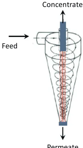
proposed hybrid configuration module. Streamlines with a gradient of velocities inside the hydrocyclone may promote displacement in the polarized layer near the membrane surface.
Feed
Concentrate
Permeate
Figure 1. Hybrid module design. Hollow fiber membranes are placed in the central region.
The electrochemical method
The electrochemical method is used under mass transfer limiting conditions and may be applied to determine local and average values of the mass transfer coefficient at a solid-liquid interface (Mizushina, 1971, Lin et al., 1951, Szánto et al, 2008, Wilk, 2014).
The mass transfer in an electrolytic system consists of the transfer of ions from the bulk of the solution toward the electrode surface through contributions of migration, diffusion and convection. Considering a dilute solution without solute-solute interactions but with a stationary regime and unidirectional flux perpendicular to the electrode surface, the fluxes of the species can be expressed by the contributions of migration, diffusion and convection governed by the Nernst-Planck equation as follows:
v
C
C
D
C
D
RT
F
n
J
i i i i i ii
where Ji is the species flux, ni is the number of electrons per mol in the reaction, F is Faraday´s constant, R is the universal gas constant, T is the temperature, Di is the species diffusion coefficient, Ci is the species concentration, Ñf is the potential gradient, and v is the bulk fluid velocity. The current through the circuit can be expressed according to Faraday’s Law which is proportional to the flux of species i (cations).
e i
i i
FA
n
I
J
where Ii is the limiting current generated in the system and Ae is the area of the electrode (cathode).
For mass transfer to be predominantly diffusive, some considerations should be made. According to Mizushina (1971) and Bard and Faulkner (2001), when the mass transfer is unidirectional and perpendicular to the electrode surface, the convection term is not considered because there is no permeation in this direction. The electrical potential gradient can be eliminated by adding excess non-reactive electrolyte to the solution. These electrolytes do not react on the electrode surface, and they provide a high conductivity when compared with the reactive species present in the electrolytic system. With these considerations, the contributions of migration and convection can be eliminated from Equation 1, and the flow of the reactive species includes only the diffusive term. Combining Equations 1 and 2,
y
C
D
A
F
n
I
ii e i
i
∂
∂
=
The Nernst diffusion layer considers that the concentration gradient in the boundary layer times the diffusion coefficient equals the flux at the electrode surface (Futselaar, 1993). Integrating Equation (3) gives:
(
bi si)
i e i
i
C
C
D
A
F
n
I
=
,−
,δ
where Cb,i is the species concentration in the bulk solution, Cs,i is the species concentration of the electrode surface, and d is the thickness of the Nernst diffusion layer. A null concentration is assumed at the electrode surface because of the increasing potential difference between the anode and cathode, and when this difference is sufficiently high, the entire electrolyte reacts, thus reducing its concentration to nearly zero. Under this condition, the limiting step is the mass transfer in the liquid phase. The mass transfer coefficient can be calculated from the limiting steps, (2)
(3)
(4)
L. S. de França Neta, C. P. Borges and A. C. Habert 792
together with equation (4), and the coefficient Di/d is replaced by the mass transfer coefficient (KL), leading to the following expression:
i b e i
i L
C
A
F
n
I
k
,
=
When the mass transfer is the limiting step, concentration polarization will occur in the direction of the electrodes where redox reactions occur. When the concentration of the limiting electrolyte is null at the electrode surface, the mass transfer coefficient can be easily related to the electric current density because the determination of the limiting current of the electrolyte system mass transfer coefficient is determined from equation 5. Figure 2 shows a typical current-voltage illustration, where the plateau represents the limiting condition, corresponding to the assumptions made to develop equation (5).
Figure 2. A typical current-voltage curve.
A continuous increase in the electrical potential results in a further increase in the current density because of water dissociation.
EXPERIMENTS
Electrolytic solution and electrodes
The current density is correlated with the mass transfer coefficient (KL) when only one type of reaction occurs on the surface of an electrode in an electrolytic system. To determine KL, an electrolyte solution composed of the redox couple potassium ferrocyanide (K4Fe(CN)6 - VETEC) and potassium ferricyanide (K3Fe(CN)6 - VETEC) with an excess of potassium hydroxide (KOH - VETEC) as the unreactive electrolyte was used. The electrolytic solution used for determining the mass transfer coefficient was potassium ferrocyanide (5.35 x 10⁻³ mol/L) and potassium ferricyanide (8.56 x 10⁻⁴ mol/L) in the presence of an excess (0.5 mol/L) of potassium hydroxide as the inert electrolyte (Borges, 1993).
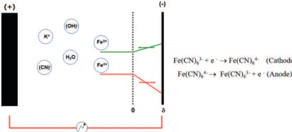
To evaluate the efficiency of the newly proposed membrane module, the mass transfer coefficient was determined for this new configuration and compared with that of a conventional configuration of a membrane module with cross-flow. To determine the mass transfer coefficient inside the modules, an electrode was constructed using nickel wire. Nickel electrodes in the form of thin wires were put close to the membrane surface inside each hollow fiber module (cathode). Another nickel electrode in the form of a flat plate was also placed in another position within the system (anode). To ensure limiting conditions and to obtain the concentration polarization effect only in the electrode positioned inside the module, its area needed to be smaller than that of the other electrode. In this system, the oxidation of potassium ferrocyanide to potassium ferricyanide occurred at the anode and, for the reverse reaction, it occurred at the cathode, as indicated in Figure 3.
This redox system is stable in alkaline solutions, and the chemical polarization at the cathode is reduced. Oxidation
Figure 3. Diffusive transport near the cathode and oxidation of potassium ferricyanide (K3Fe(CN)6) to potassium ferrocyanide (K4Fe(CN)6).
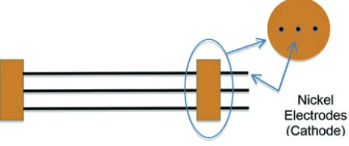
by dissolved oxygen was avoided by bubbling nitrogen in the solution before the experiment. Each module was equipped with three nickel wires. For the longitudinal module, the length and diameter of the wires were 20.0 cm and 0.05 cm, respectively, corresponding to an eff ective area of 3.14 cm2, and the wires were placed inside 1.9 cm diameter PVC tubes (Figure 4).
Figure 4. Nickel wires positioned longitudinally.
For the new hybrid module (Figure 1), the length and diameter of the three wires were 30.0 cm and 0.05 cm, respectively, corresponding to an active area of 6.50 cm2, and the wires were placed in a PVC support tube with a length of 8.0 cm and a diameter of 1.9 cm. The anode was prepared from a fl at nickel sheet (99.9% - Aldrich) with an external area of 112.0 cm2. The electrode was also placed in a PVC fi tting and positioned inside a PVC tube with a 1.9 cm diameter.
The measurement system used to determine the mass transfer coeffi cient using the electrodes and the electrolyte system will be discussed later.
Hollow fi ber membranes
The hollow fi ber microfi ltration membranes were used in conjunction with the electrolytic nickel wires. The fi ber packing density (the membrane area per volume of cylindrical module) was a variable in the bundles containing the nickel wires. The variation in the packing density was used as a parameter to evaluate the functionality of the hollow fi bers as promoters of secondary fl ows within the permeation module. During the development of this work, only the circulation of the solution by the permeation modules without any permeation of the electrolyte solution was examined. Hollow fi ber membranes were prepared in the laboratory. The fi bers were prepared from poly(ether imide) (ULTEM/GE), and poly(vinylpyrrolidone) (Fluka) using a wet-spinning technique (Faria et al., 2002, Habert et al., 2006, Pereira et al., 2003). Three fi ber packing densities were investigated, namely 500, 1000 and 1500 m2/m3. The assembly of the hollow fi ber bundles with the nickel wires is illustrated in Figure 5, and the Figure 6 shows the bundles inside the module.
Figure 5. An MF module assembled with hollow fi bers and nickel wires ready for mass transfer evaluation.
Figure 6. Bundles of hollow fi ber membranes inside the (a) longitudinal and (b) hybrid module.
Experimental apparatus
An experimental system was constructed to determine the current density generated by the electrochemical system. The current density value was used for the subsequent determination of the mass transfer coeffi cient (KL). This is similar to a tangential fl ow microfi ltration system; however, there is no fi ber permeation. The mass transfer coeffi cient determination was completed in the experimental set-up shown in Figure 7, which uses the electrodes and the electrolyte solution.
L. S. de França Neta, C. P. Borges and A. C. Habert 794
current corresponded to the new steady state condition. A frequency inverter controlled the rotation of the pump, allowing the change in flow regime. The voltage-current density plots were extracted from data obtained for each hydrodynamic regime run, which were performed at room temperature (25 ºC).
Figure 7. Electrochemical flow system for mass transfer evaluation. (1) feed tank, (2) pump, (3 and 5) pressure gauges, (4) cathode module, (6)
flowmeter, (8) anode tube, (7) valve and (9) electrical supply.
For the longitudinal module, the Reynolds number (Re) (equation 6) was calculated from the effective diameter using Equation (7).
ed
v
Re
π
ue
A
d
=
4
where de is the effective diameter, g is the fluid kinematic viscosity and Au is the effective cross sectional area given by,
tf tm u
A
A
A
where Atm and Atf are cross sectional areas of the module and the hollow fibers, respectively.
For the hybrid module, the Re number was calculated identically to traditional hydrocyclone equipment and is based on the average flow velocity in the entry of the cyclone (Massarani, 2002):
fc
c
u
D
Re
where Dc is the diameter in the cylindrical region in
the hydrocyclone, uc is the average flow velocity in the cylindrical region, and rf and m are the density and fluid viscosity, respectively. The average flow velocity is:
2
4
c c
D
Q
u
π
=
where Q is the feed flow in the module.
RESULTS AND DISCUSSION
Nickel electrodes
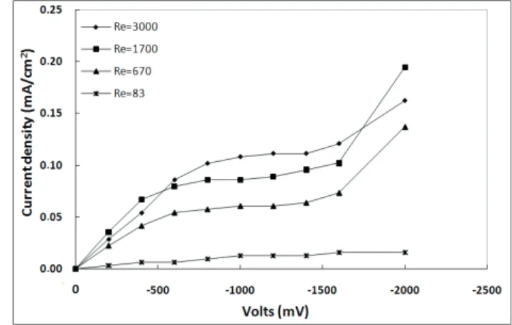
Modules with only nickel electrodes (Figure 4) were first tested at different feed flow rates (with Reynolds numbers ranging from 83 to 3000) to validate the methodology and the experimental set-up applied for determining the mass transfer coefficients. The electrical current was measured for the electrical potential difference from 0 to -2000 mV. The experiments were performed with the central electrode module permeation because there were no variations in the current density in the external electrodes. These experimental results are shown in Figure 8.
Figure 8. Electrical current and voltage curves at different Reynolds numbers. Cathode area = 3.14 cm2 and anode area = 112 cm2.
It can be observed that the polarization plateau, i.e., the limiting current density, is attained for different Reynolds numbers. In the condition of current limit, the Fe3+ is reduced quickly on the electrode surface due to an ion diffusive transport process from the solution to the electrode surface. The main diffusive transport occurs due to the presence of KOH as a non-reactive electrolyte that inhibits the transport of Fe 3+ by migration. In this region, the current is independent of the applied voltage, characterizing the null concentration of the electrolyte at the electrode surface.
At higher Reynolds numbers, there is a tendency to reduce the plateau, which reflects a decrease in the (6)
(7)
(8)
(9)
polarization layer thickness. At electrical potential values higher than -1600 mV, the polarization plateau is no longer sustained, indicating dissociation of the water molecules or the presence of electrokinetic effects (Mizushina, 1971, Lin et al., 1951).
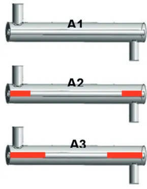
The effects related to the stagnant zones and the disturbance in the flow stream and the secondary flow due the feed flow solution were investigated as a function of the entrance effects. These effects in the longitudinal module were investigated by reducing the electrode area, particularly at the edges of the module (Figure 9). The results are shown in Figure 10 for the experiments run at different hydrodynamic regimes.
Figure 9. Comparison of the cross sectional area of the electrode in the
permeation module to test the entrance effects. A1 = 3.14 cm2, A2 = 2.20
cm2 and A3 = 1.26 cm2. The red lines represent wire electrical isolation.
Figure 10. Effect of the mass transfer coefficient as a function of the Reynolds number and electrode area.
According to the results shown in Figure 10, with the reduction in the area at the ends of the electrode in A1 and A2, there is a slight increase in the mass transfer coefficient. This result suggests that, for this module configuration, the velocity profile inside the module is not well developed and the input hydrodynamic effects are present and affect this transfer process. For the electrode A3, a slight increase in the mass transfer coefficient was observed until Reynolds number equal to 1700. However, with the increase in the Reynolds number from 1700 to 3000, there was a reduction in this value, indicating that the end zones are responsible for a greater impact on the flow and contribute to the increase in the global mass transfer coefficient inside the module. These results emphasize that the Sherwood correlations cannot be used to determine the mass transfer coefficient of membrane modules on a laboratory scale.
The hybrid module described above was evaluated and compared with the longitudinal module by determining the mass transfer coefficient. Due to limitations in the experimental system, it was possible to investigate the mass transfer coefficient behavior for Reynolds numbers values of 3000, 1500 and 1000. Similar to the longitudinal module, the initial evaluation of the new hybrid module was performed only with nickel wires inside the module. Figure 11 shows the mass transfer coefficients (KL) for both modules, longitudinal and hybrid, as a function of the Reynolds number.
These results indicate an improvement in the flow regime inside the proposed module because it increases the mass transfer coefficient for the same value of Reynolds number. The improvement in the flow regime inside the module results in the reduction of the polarization layer close the electrode surface that will increase the mass transfer coefficient. Similar to the longitudinal module, it was also observed that increasing the Reynolds number results in an increase in the mass transfer coefficient.
Figure 11. Comparison between the longitudinal and hybrid modules at
L. S. de França Neta, C. P. Borges and A. C. Habert 796
Effect of the module packing density
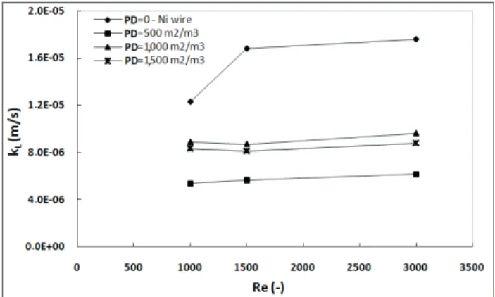
The membrane packing density (PD) in the modules was evaluated at similar flow conditions, keeping the nickel wire (cathode) located inside the bundle hollow fiber, as indicated in Figure 5. To investigate whether the hollow fiber membrane acted as a turbulence promoter inside the permeation module, the PD was fixed at 500, 1000 and 1500 m2/m3. The effect of flow without hollow fiber membranes was evaluated using only one nickel wire (PD = 0). The results are shown in Figures 12 and 13 for the longitudinal and hybrid modules, respectively.
The results presented in Figure 12 clearly show that the presence of hollow fibers inside the longitudinal module increases the mass transfer coefficient when compared with the module that has only nickel wire. This effect can be attributed to a better hydrodynamic condition inside the module, as the hollow fibers act as turbulence promoters. However, it appears that the packing density effect was more effective between 500 and 1000 m2/ m3. For PD of 1000 and 1500 m2/m3, it is not possible to observe significant differences between the two packing density values, indicating a limit of the KL value where the secondary flow promoted by the fibers is unable to further reduce the boundary layer thickness.
Figure 13 shows the results obtained with the hybrid module and three different packing densities at different flow conditions. For the hybrid module, the packing density was calculated considering the central region of the module.
When compared to the module with only nickel wires, the results shown in Figure 13 reveal that the presence of hollow fibers inside the module did not act as turbulence promoters, and they lead to a reduction in KL. This result can be attributed to the region where the fibers are located, i.e., in the central region of the hybrid module, which is a low-speed region. Increasing the packing density from 500 to 1000 m2/m3 resulted in a small increase in the mass transfer coefficient; however, when the density was increased from1000 to 1500 m2/m3, there was a slight decrease in the weighting value inside the module, showing that increasing the packing density does not result in an increase in the mass transfer coefficient. This low-velocity region may be responsible for the increased thickness of the polarized layer near the electrode surface, hindering the electrolytic reaction at the electrode surface. Comparing the values of the mass transfer coefficient for the longitudinal and hybrid module in the presence of the hollow fiber membranes, the longitudinal module presented a better performance than the hybrid module. This result emphasizes the performance of the hollow fibers membrane as turbulence promoters.
CONCLUSIONS
The apparent mass transfer coefficients were successfully determined by the electrochemical method. The electrochemical technique allows the determination of this coefficient more accurately and close to the hydrodynamics flow, unlike the mathematical correlations that are applied to established system conditions, thus elevating the associated error in determining this parameter in modules for experimental analysis, as observed in this work. The increased value of the mass transfer coefficient for the hybrid module indicated an improvement in the flow regime inside the new geometry when compared to longitudinal modulus. The effect of the presence of the hollow fibers in permeation modules was investigated and, for the longitudinal modules, hollow fibers acted as turbulence promoters, especially when the packing density was in the range of 500 to 1000 m2/m3. An opposite effect was observed for the new hybrid module proposed, which showed lower performance compared with the longitudinal
Figure 12. Effect of the membrane packing densities (PD) on mass transfer for longitudinal modules.
Figure 13. Effect of membrane packing density (PD) on the mass
module. These results were interpreted as a contribution of regions with low velocities that resulted in increased thickness of the polarization layer near the electrode surface. Nevertheless, the electrochemical method used to evaluate the apparent mass transfer proved to be an efficient tool to compare different permeation modules or to assist in module design. The module proposed using cyclonic flow has great potential for use in microfiltration and ultrafiltration; however, studies should also be carried out to optimize this configuration.
NOMENCLATURE
Ae - area of the electrode (cathode) (m 2)
Au – effective cross section (m2)
Atf - cross sectional area of hollow fibers (m2)
Atm - cross sectional area of the module (m2)
Ci - species concentration (mol.L -1)
Cb,i - species concentration in the bulk solution (mol.L -1)
Cs,i - species concentration of electrode surface (mol.L -1)
Dc - diameter in the cylindrical region of the hydrocyclone (m), Di - species diffusion coefficient (m2.s-1)
de - effective diameter (m) F - Faraday´s constant (C.mol-1)
Ii - limit current (mA)
Ji - species flux (mol.s -1.m-2)
KL - mass transfer coefficient (m.s -1)
MF - microfiltration process
MSP - membrane separation process ni - number of electrons per mol PD - packing density (m2.m-3)
Q - the feed flow in the module (m3.s-1)
R - universal gas constant (J.mol-1.K-1)
Re - Reynolds number (-) T – temperature (ºC)
uc - average flow velocity in the cylindrical region (m.s-1)
- potential gradient (mV)
Ci – concentration gradient (mol.L -1)
v- bulk fluid velocity (m.s-1)
δ - thickness of the Nernst diffusion layer (m)
γ -fluid kinematic viscosity (m2.s-1)
ρf – fluid density (kg.m -3)
μ - fluid viscosity (kg.m-1.s-1)
REFERENCES
Baker, R. W. Membrane Technology and Applications. Second Edition. John Wiley & Sons, 2012. ISBN: 978-0-470-74372-0
Bard, A. J. and Faulkner, L. R. Electrochemical Methods Fundamentals and Applications. Second Edition. John Wiley & Sons, 2001. New York.
Barthès, M., Mazue, G., Bonnet, D., Viennet, R, Hihn, J., Bailly,
Y., Characterization of the activity of ultrasound emitted in a
perpendicular liquid flow using Particle Image Velocimetry
(PIV) and electrochemical mass transfer measurements. Ultrasonics, 59, 72–78 (2015).
BCC Research. The Global Market for Membrane Microfiltration.
July 2013. https://www.bccresearch.com/market-research/ m e m b r a n e a n d s e p a r a t i o n t e c h n o l o g y / m e m b r a n e
-microfiltration-mst028e.html
Berrich, E., Aloui, F., Legrand, J., Experimental validation and critical analysis of inverse method in mass transfer using electrochemical sensor. Experimental Thermal and Fluid Science, 44, 253–263 (2013).
Böhm, L., Drews, A., Kraume, M. Bubble induced shear stress in flat sheet membrane systems—Serial examination of single bubble experiments with the electrodiffusion method. Journal
of Membrane Science, 437 (15): 131-140 (2013).
Böhm, L., Jankhah, S., Tihon, J., Bérubé, P. R., Kraume, M., Application of the Electrodiffusion Method to Measure Wall
Shear Stress: Integrating Theory and Practice. Chemical Engineering & Technology, 37 (6), 938- 950 (2014).
Borges, C.P., Composite Hollow Fiber for Trace Organics
Removal from Aqueous Solution by Pervaporation. D.Sc.
Thesis, Chem. Eng. Program, Fed. University of Rio de Janeiro Brasil (1993).
Brewster, M. E., Chung, K. Y., Belfort, G. “Dean vortices with wall flux in a curved channel membrane system. 1. A new
approach to membrane module design”, Journal of Membrane Science, 81, 127-137 (1993).
Chung, K. Y., Bates, R., Belfort, G. “Dean vortices with wall flux in a curved channel membrane system. 4. Effect of vortices on permeation fluxes of suspensions in microporous membrane”,
Journal of Membrane Science, 81, 139-150 (1993a).
Chung, K. Y., Edelstein, W. A., Belfort, G. “Dean vortices with wall flux in a curved channel membrane system. Two dimensional magnetic resonance imaging of the velocity field
in a curved impermeable slit”, Journal of Membrane Science, 81, 151-162 (1993b).
Davis, R.H., “Microfiltration”. In: WINSTON HO, W.S. and Sirkar, K.K., Membrane Handbook, chapter 8. Ed. Reinhold
V. N., New York. 1992.
Faria, L. F., DI Luccio, M. and Nobrega, R., Development and
Characterization of Microfiltration Hollow-Fiber Modules
for Sterilization of Fermentation Media, Brazilian Journal of Chemical Engineering, 19 (2),141-150 (2002).
Fulton, B.G., Redwood, J., Tourais, M., Bérubé, P.R. Distribution of surface shear forces and bubble characteristics in full-scale
gas sparged submerged hollow fiber membrane modules.
Desalination, 281:128-141 (2011).
Futselaar, H., The transverse flow membrane module.
Construction, performance and applications. Ph.D. Thesis, University of Twente, Netherlands (1993).
Gaucher, C., Legentilhomme, P., Jaoue N, P., Comiti, J. and
Pruvost, J., Hydrodynamics study in a plane ultrafiltration
L. S. de França Neta, C. P. Borges and A. C. Habert 798
Habert, A. C., Borges, C. P., Nobrega, R. Processos de Separação por Membrana – Série Escola Piloto em Engenharia Química- COPPE/UFRJ. Rio de Janiero: Editora e-papers. (2006).
Hall, D.W., Scott, K. and Jachuck, R.J.J., Determination of mass transfer coefficient of a cross-corrugated membranes reactor by the limiting-current technique, International Journal of
Heat and Mass Transfer, 44, 2201-2207 (2001).
Keirsbulck, L, Labraga, L, Gad-el-Hak, M. Statistical properties of wall shear stress fluctuations in turbulent channel flows.
International Journal of Heat and Fluid Flow. 37, 1–8 (2012).
Knops, F. N. M., Futselaar, H., Rácz, I. G. The transversal flow microfiltration module. Theory, design, realization and
experiments, Journal of Membrane Science, 73, 153-161 (1992).
Koutsou, C.P, and Karabelas, A.J., A novel retentate spacer
geometry for improved spiral wound membrane (SWM) module performance. Journal of Membrane Science, 488, 129–142 (2015).
Li, F., Meindersma, W., Haan, A.B. and Reith, T., Experimental
validation of CFD mass transfer simulations in flat channels
with non-woven net spacers, Journal of Membrane Science, 232, 19-30 (2004).
Lin, C.S., Denton, E.B., Gaskill, H.S. and Putnam, G.L.,
Diffusion-controlled electrode reactions, Engineering and
Process Development, 43, 2136-2143 (1951).
Massarani, G. Fluidodinâmica em sistemas particulados. Rio de Janeiro: Editora e-papers. (2002).
Matson, S.L. “Membrane bioseparation”. In: NOBLE, R.D.,
STERN, S. A. (Ed). Membrane Separations Technology. Principles and Aplications, chapter 8. Ed. Elsevier Science. 1995.
Mallubhotla, H., Belfort, G. “Dean vortex stability using magnetic resonance flow imaging and numerical analysis”.
AIChE Journal, 5, 1126-1130 (2001).
Michaels, A. S., Membranes, membrane processes, and their applications: Needs, unsolved problems, and challenges of the 1990’s, Desalination, 77, 5-34 (1990).
Mizushina, T. “The electrochemical method in transport
phenomena”. In: Irvane, T.F., Hartnett, J.P. (Ed). Advances in heat transfer. v.7, p.87-161. Academic Press, N.Y., London. 1971.
Jankhah, S. and Bérubé, P. R. Power induced by bubbles
of different sizes and frequencies on to hollow fibers in
submerged membrane systems. Water Research, 47 (1), 6516-6526 (2013).
Káňavová, N., Machuča, L., Tvrznik, D., Determination of
limiting current density for different electrodialysis modules.
Chemical Papers, 68 (3): 324–329 (2014).
Káňavová, N., Krejčí, A., Benedeková, M., Doležel, M., Machuča, L., Mass transfer examination in electrodialysis
using limiting current measurements. Chemical Papers, 69 (4), 553–559 (2015).
Mulder, M. Basic Principles of Membrane Technology.
Netherlands, Kluwer Academic Publishers, 1996.
Pereira,C.C., Monteiro,C.A., Habert, A.C., et al, 2003.
“Microfiltração de água utilizando módulos de fibras ocas para purificação de uso residencial”. In: 4° Congresso
Ibero-americano em Ciência e Tecnologia de Membranas, pp. 205-210, Florianópolis, Brasil.
Ripperger, S. and Altmann, J., Crossflow microfiltration – state of the art, Separation and Purification Technology, 26 (1), 19-31
(2002).
Sarkar, A., Moulik, S., Sarkar, D., Roy, A., Bhattacharjee, C., Performance characterization and CFD analysis of a novel
shear enhanced membrane module in ultrafiltration of Bovine
Serum Albumin (BSA). Desalination, 292, 53–63 (2012).
Scott, K., Jachuck, R.J.J. and Hall, D.W., Crossflow microfiltration
of water-in-oil emulsion using corrugated membranes,
Separation and Purification Technology, 22-23, 431-441 (
2001).
Sakakibara, Y., Flora, J.R.V., Suidan, M.T., Biswas, P., Kuroda, M., Measurement of mass transfer coefficients with an
electrochemical method using dilute electrolyte solutions. Wat. Res., 28, 9-16 (1994).
Strathmann, H., Membrane separation processes: current relevance and future opportunities, AIChE Jounal, 47 (5), 1077-1087(2001).
Szánto D. A., Cleghorn, S., Ponce-de-León, C., Walsh, F. C., The
limiting current for reduction of ferricyanide ion at nickel: The importance of experimental conditions. AIChE Jounal, 54 (3), 802-810 (2008).
Van der Horst, H.C. and Hanemaaijer, J.H., Cross-flow microfiltration in the food industry. State of the art,
Desalination, 77, 235-258 (1990).
Wilk, J., A review of measurements of the mass transfer
in minichannels using the limiting current technique.
Experimental Thermal and Fluid Science, 57, 242–249 (2014).
Zhang, J., Li, J., Duke, J., Hoang, M., Xie, Z., Groth, A., Tun, C., Gray, S., Influence of module design and membrane