ISSN 0104-6632 Printed in Brazil
www.abeq.org.br/bjche
Vol. 33, No. 02, pp. 287 - 296, April - June, 2016 dx.doi.org/10.1590/0104-6632.20160332s20150234
Brazilian Journal
of Chemical
Engineering
NUMERICAL SIMULATION OF THE
INCOMPRESSIBLE TURBULENT FLOW OF A
BINARY MIXTURE OF AIR-WATER VAPOR:
APPLICATIONS IN DRYING PROCESS
P. S. B. Zdanski
1*and D. Silva
21
State University of Santa Catarina, UDESC, Department of Mechanical Engineering, Campus Universitário Avelino Marcante s/n, Zona Industrial Norte, 89219-710, Joinville - SC, Brazil.
E-mail: [email protected] 2
Tupy S.A, Joinville - SC, Brazil.
(Submitted: April 15, 2015 ; Accepted: May 6, 2015)
Abstract - The present work deals with numerical simulation of the incompressible turbulent flow of a binary mixture air-water vapor inside channels. Calculations are performed using the RANS (Reynolds Average Navier-Stokes Equations) formulation in addition to the standart k-ε turbulence model. The mathematical model is discretized by a finite difference scheme, being adopted second order accurate expressions for both convection and diffusion terms. The mesh arrangement is collocated and artificial dissipation terms are added to control the odd-even decoupling problem. The numerical scheme is applied to solve the flow of a binary mixture of air-water vapor inside plane channels and sudden expansions. The validation performed indicates that the present method reproduces satisfactorily the literature data for both concentration profiles and Sherwood number. Furthermore, the parametric analysis performed indicates that the drying process (wall mass flux) is very sensitive to the flow parameters investigated, i.e., inlet flow velocity and channel expansion ratio.
Keywords: Binary mixture; Turbulent flow; Numerical analysis; Finite difference method.
INTRODUCTION
The turbulent flow of binary mixtures occurs in practical problems of the chemical and mechanical engineering areas. In the convective drying process, water vapor is removed from moist objects (e.g. wood, food, etc.), being transported by the hot air stream. It is important to mention that convective drying is the most used method in agricultural, food, paper and timber processing industries (Mohan and Talukdar, 2010). In general applications, convective drying of moist objects conjugates heat and mass transfer both inside the solid and in the flowing me-dium (Vaz Jr et al., 2013). The understanding of the
related physics of the problem is important for indus-trial process control.
Navier-Stokes equations subjected to laminar flow condi-tions. The results obtained indicate a correlation be-tween drying rate in the solid and the flow behaviour. In a similar route, Lamnatou et al. (2009) studied numerically the drying process of a moist object (a porous sliced wood) subjected to incompressible laminar flow of a binary mixture inside a channel. The authors analysed the effects of two flow con-figurations, and the results indicated that using the upstream flow divider device produced a higher mass transfer rate at the surface of the moist object (en-hancing the drying rate).
In other interesting practical applications, some literature works solve the flow of a binary mixture to study both the environmental problem of pollutant dispersion and the chemical corrosion of metallic sur-faces (Xiong et al., 2014; Lateb et al., 2013; Arellano et al., 2013; Arellano and Rivera, 2014). The afore-mentioned works adopted the numerical methodol-ogy to study practical aspects of the problem, i.e., to estimate the mass flux of the chemical component on the surface, the concentration of the pollutant be-tween the buildings in a city, etc.
The present work deals with the 2D numerical simulation of turbulent flow of a binary mixture (air-water vapor) aiming to study some aspects of the con-vective drying process. The numerical scheme ap-plied by the authors was originally proposed for solving turbulent Newtonian flows (Zdanski et al. 2004). The present methodology was also applied successfully to solve non-Newtonian polymer melt flows inside channels (Zdanski et al., 2008; Zdanski and Vaz Jr., 2011). Therefore, the present work per-forms an extension of the author’s methodology for solving turbulent flows of binary mixtures, including the solution of the concentration equation. The re-sults obtained indicate that the present method repro-duces satisfactorily the literature data for both con-centration profiles and Sherwood number. Further-more, the parametric analysis performed shows that the drying process (mass flux at the channel walls) is dramatically affected by the flow parameters investi-gated, i.e., inlet flow velocity and channel expansion ratio.
THEORETICAL FORMULATION
Governing Equations
The mathematical model employed corresponds to the classical Reynolds Averaged Navier-Stokes Equations (RANS) together with the Boussinesq eddy viscosity approximation. Within this framework, the
mass, linear momentum, energy and chemical spe-cies conservation laws are solved to obtain the aver-age velocities, pressure, temperature and concentration profiles of the flow. In cartesian tensor notation, the equations are given by (Kays and Crawford, 2005):
i 0 iu x
, (1)
i
j i e i je
j i j j i
u u u
u p u
t x x x x x
, (2)
p
i p
e
i i i
c T u c T T
k
t x x x
, (3)
e
i
AB
i i i
C u C C
D
t x x x
, (4)
where e T, ke k kT and
e T
AB AB AB
D D D
are the effective diffusion coeficients, and
2 3
e
p p is the effective pressure. In the pre-ceding expressions, T, kT and
T
AB
D are the turbu-lent diffusion coeficients, being determined by the standard two-equation
turbulence model. In the present model, two differential equations are solved for the turbulence kinetic energy (
) and its dissipa-tion rate (), i.e.,
jj
j
T i i
T
j k j j i j
u
t x
u
u u
x x x x x
, (5)
1
2 2
j T
j j j
j
i i
T
j i j
u
t x x x
u
u u
C
x x x
C , (6)
the turbulent eddy viscosity being calculated by:
2
T C
Numerical Simulation of the Incompressible Turbulent Flow of a Binary Mixture of Air-Water Vapor: Applications in Drying Process 289
The constants appearing in the preceding equa-tions are empirically determined (Launder and Spal-ding, 1974), i.e.,
0.09
C , C11.44, C21.92,
(8) 1.0
, 1.3.
The turbulent diffusion coeficients in the energy and chemical species equations are obtained by using the analogy between linear momentum, heat and mass diffusion processes through the definition of the tur-bulent Prandtl and Schmidt numbers (Kays and Crawford, 2005),
T p T T
c k
Pr
, (9)
T T AB
Sc D
T
. (10)
The turbulent Prandtl and Schmidt numbers are assumed to be constants, being adopted common val-ues for engineering calculations PrT ScT 0.9 (Kays and Crawford, 2005). It is worth to mention that the standard turbulence model is valid only for the fully turbulent region; in the near wall regions the law of the wall for velocity, temperature and concen-tration profiles is adopted (Launder and Spalding, 1974; Kays and Crawford, 2005; Arpaci and Larsen, 1984).
Numerical Methodology
The mathematical model is discretized with a fi-nite difference scheme, second order accurate formu-lae being adopted for both the convection and diffu-sion terms. The mesh arrangement is collocated and artificial dissipation terms are added to control the odd-even decoupling problem. The pressure-velocity coupling strategy employed comprises the solution of the Poisson equation for pressure. The solution procedure follows a pseudo-transient march in time, aiming at the steady-state solution. The present work constitututes an extension of the author’s method-ology (Zdanski et al., 2004; Zdanski et al., 2008; Zdanski and Vaz Jr., 2011) for solving turbulent flows of binary mixtures. The main general steps of the present scheme are given in sequence.
The linear momentum, energy and chemical spe-cies conservation equations, as well as the turbulence
model equations, can be written in a compact form (for a 2D cartesian coordinate system)
Q E F
S
t x y
, (11)
where Q is the vector of conserved variables, E, F and S are the flux vectors containing the convection, diffusion and source terms. The vector Q is expanded in time by Taylor expansion:
1 1
m
m m Q
Q Q t
t
(12)
in which m and t are the time step and time incre-ment, respectively. Furthermore, from Equation (11) one finds:
1 1
. m m
Q E F
S
t x y
(13)
Solution of Equation (12) requires linearization of vectors E, F and S in terms of vector Q using Taylor expansion and defining the Jacobian matrices at time step m. The resulting equation may be expressed as
m m
m m
m m
m
A B
I t J Q
x y
E F
t S
x y
, (14)
where A, B and J are the Jacobian matrices, and
1
m m m
Q Q Q
is the variable delta form. In
or-der to reduce the computational effort in the numeri-cal solution of Equation (14), the approximate fac-torization technique (Beam and Warming, 1978) is introduced. Besides, to reach second order spatial accuracy, the scheme uses a central discretization for both convection and diffusion terms; however, to cir-cumvent the odd-even decoupling problem (Patankar, 1980), artificial dissipation terms are added externally. The final form of the equation is:
m
x y x y
L L Q R R , (15)
where
2 2 2 2m m
x i
A J
L I t x
x x
2 2 2 2m m
y i
B J
L I t y
y y
, (17)
4 4 4 2m m m
x e
E S Q
R t x
x x
, (18)
4 4 4 2m m m
y e
F S Q
R t y
y y
, (19)
I being the identity matrix, i and e the artifi-cial dissipation coefficients and x and y the nodal distance along the corresponding coordinate axes. Following an ADI (alternating direction implic-itly) concept, Equation (15) is solved as a sequence of two one-dimensional problems
1 1
m
y x x y
Q L L R R
, (20)
1
m m m
Q Q Q . (21)
Finally, it is important to mention that the artifi-cial dissipation coefficients
i and e are calibrated numerically and the values found to be adequate were i 0.001 and e 0.003. The complete proce-dure to control the magnitude of the artificial smooth-ing terms is described by Zdanski et al. (2004).RESULTS AND DISCUSSION
Validation/Verification of the Numerical Solution
This section comprises the validation of the numerical method applied. The flow of a binary mixture in a two-dimensional plane channel was the benchmark problem selected, i.e., the turbulent con-centration profiles and the Sherwood number dis-tribution were confronted with literature data (for three meshes). Firstly, in Fig. 1 the dimensions of the geometry are presented, i.e., the channel height h=0.011 m and the channel length L=60 h. The computational meshes adopted in the simulations are uniform with 201 × 31, 301 × 35 and 401 × 41 grid points in the streamwise and cross-sectional di-rections, respectively. Boundary conditions at the inlet plane are: uniform velocity, temperature and concentration profiles, with the Reynolds number based on the hydraulic diameter equal to 27.480. For this test, the following values were applied: ui =
18.68 m/s, Ci= 0.00788 kg/m3 and
i= 0.02 (ui)2/2,with ui, Ci and i being the inlet velocity,
concen-tration and turbulent kinetic energy, respectively. At the exit section, parabolic conditions (null derivatives) are specified for all the variables, except for pressure, whose variation is considered to be linear. At the solid walls, a constant mass flux of the chemical spe-cies (water vapor) is imposed, No"w= 0.025 kg/m2s.
Figure 1: Illustration of the two-dimensional channel with the main dimensions.
Figure 2 shows the computed non-dimensional concentration profiles at the channel exit section (L/h = 60), corresponding to the fully developed flow region. As can be seen in the figure, the results clearly indicate that the numerical scheme reproduces satis-factorily the literature concentration profile for the three meshes tested. The benchmark solution in this case is the classical correlation according to Kader (1981), that was developed to fit the experimental data for fully developed flow regions in plane chan-nels and circular ducts. The non-dimensional con-centration is defined as C+=(C-Cw)/C,* where
C*=No"w/u* and u*=C0.5 0.25 (u* being the shear velocity), and the parameter y+ (non-dimensional distance from the wall) is given by yu y* .
08 10 12 14 16
10 100 1000
C +
y +
Analytical correlation (Kader,1981) 201 x 31 mesh points
301 x 35 mesh points 401 x 41 mesh points
Figure 2: Comparisons between analytical correla-tion and computacorrela-tions for the concentracorrela-tion profile in the fully developed flow region.
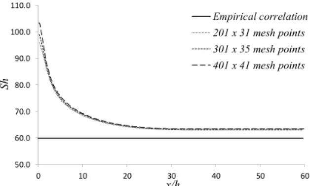
Sher-Numerical Simulation of the Incompressible Turbulent Flow of a Binary Mixture of Air-Water Vapor: Applications in Drying Process 291
wood number (Sh) expresses the local convective mass transfer coefficient (hm), i.e.,
m h
AB
h D Sh
D
, (22)
AB w m
m w
C D
y h
C C
, (23)
A m
m
uCdA
C
u A
, (24)where Cm is the bulk concentration of the chemical
species, Cw is the concentration at the channel walls,
hm is the local convective mass transfer coefficient,
Dh is the hydraulic diameter and um is the average
velocity in the channel cross section.
50.0 60.0 70.0 80.0 90.0 100.0 110.0
0 10 20 30 40 50 60
Sh
x/h
Empirical correlation 201 x 31 mesh points 301 x 35 mesh points 401 x 41 mesh points
Figure 3: Comparisons between the empirical corre-lation and computations for the Sherwood number.
The results presented in Figure 3 indicate a good agreement between the numerical solution and the empirical correlation in the fully developed flow region (x/h
25), the error being around 6%. It is important to mention that the Sherwood number for the fully developed flow region is obtained from the empirical correlation of Dittus-Boelter (Incropera et al., 2007), i.e.,0.8 0.4
0.023Re
m h
Dh AB
h D
Sh Sc
D
, (25)
ReDh and Sc being the Reynolds and molecular
Schmidt numbers. Finally, it is important to mention that the numerical results obtained with the present scheme (see Figures 2 and 3) are clearly mesh independent.
Flow in a Wood Dry Kiln
A typical convective wood dry kiln comprises various channels that are formed between the wood stacks. The previous numerical results of Possamai (2013) and Zdanski et al. (2015), assessing the aero-dynamic effects in a dry kiln, have shown that flow inside the channels can be highly non-uniform. Be-sides, according to the same authors, flow stagnation regions and recirculation zones are typically found in a dry kiln device. Therefore, this section aims at studying the effects of the aforementioned flow char-acteristics on the drying rate of the wood stack (mass flux in the channel walls).
The geometry adopted in the simulations, along with the flow configuration at the channel entrance section, is shown in Figure 4. A parametric study was performed, i.e., the inlet flow velocity and the inci-dence angle (Â) were varied to assess the influences on mass transfer at the channel walls. In the present test the boundary conditions were specified similarly to the validation case, except the concentration at the walls that was set to a constant value, Cw = 0.025
kg/m3, and the inlet flow velocity was varied. The computational mesh adopted in the simulations is uniform with 201 x 31 grid points, the channel di-mensions being equal to the validation case.
Figure 4: Illustration of the two-dimensional channel with variable flow incidence angle.
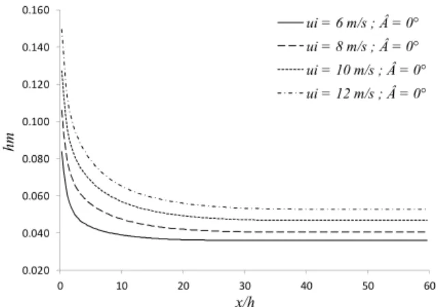
Firstly, in order to study the effects of distinct inlet flow velocities on mass flux at the channel walls, parallel flow was considered (Â=0). The flow velocities tested were ui = 6, 8, 10 and 12 m/s, values
drastically the mass transfer at the channel walls (and probably the drying rate of the wood stacks).
0.020 0.040 0.060 0.080 0.100 0.120 0.140 0.160
0 10 20 30 40 50 60
hm
x/h
ui = 6 m/s ; Â = 0° ui = 8 m/s ; Â = 0°
ui = 10 m/s ; Â = 0° ui = 12 m/s ; Â = 0°
Figure 5: Convective mass transfer coefficient for distinct inlet flow velocities (Â=0).
The results of Figure 6 show the convective coef-ficient for non-vanishing incidence angle at the chan-nel entrance. It is important to mention that the afore-mentioned flow topology typically occurs inside a wood dry kiln (Possamai, 2013; Zdanski et al., 2015), being worthy of investigation. The entrance velocity ui was set variable with respect to the incidence
angle in order to produce an uniform mass flow of the mixture in the channel for the cases tested (Â=0°,10°, 20°, 30° and 40°), i.e.,
A
m
udActe. (26)The results of Figure 6 clearly indicate that mass transfer of the chemical species (water vapor) at the channel walls was enhanced in the entrance flow region (x/h<25) as the flow incidence angle increased.
0.020 0.040 0.060 0.080 0.100 0.120 0.140
0 10 20 30 40 50 60
hm
x/h
 = 0°  = 10°  = 20°  = 30°  = 40°
Figure 6: Convective mass transfer coefficient for distinct incidence angles (Â).
The physical scenario is dominated by the stagna-tion region formed at the channel upper wall, that leads to enhancement in the convective mass transfer process. Otherwise, in the fully developed flow re-gion (x/h>25) the convective coefficient is basically constant (an expected result due to the occurrence of similar velocity profiles in this region).
Finally, in order to conclude this section Figure 7 shows the results for the average Sherwood number along the channel length for Â=10°and 40° and for all velocities tested, i.e.,
s
s
m s
A m
s
A
h dA
h
dA
and mABhh D Sh
D
. (27)
The results show basically a linear variation be-tween Sherwood and Reynolds numbers. The con-vective mass transfer enhancement was also ob-served when the flow presented an incidence angle, this behaviour being related to the stagnation region formed at the upper wall.
Figure 7: Average Sherwood number as function of Reynolds number for Â=0°and40°.
Flow in Channels with Sudden Expansion
Numerical Simulation of the Incompressible Turbulent Flow of a Binary Mixture of Air-Water Vapor: Applications in Drying Process 293
mesh uniform with 901 × 31grid points in the x and y directions, respectively. The velocity at the inlet section was set as follows: ui = 16 m/s for the
chan-nel with expansion ratio ER = (h-s)/(h) = 1/2; ui= 12
m/s for ER = 2/3and ui= 10 m/s for ER = 5/6.
Fi-nally, it is important to mention that uiwas set
vari-able with respect to the expansion ratio in order to produce an uniform mass flow of the mixture in a channel for the cases tested (see Equation (26)).
݄
ܮ ݏ
ݑ
ܶ
ܥ
ݔ ݕ
Figure 8: Illustration of the two-dimensional channel with sudden expansion section.
The purpose of this section was to study the effects of the expansion ratio on the mass flux of the chemi-cal species (water vapor) at the solid walls. Figure 9 shows the results for the convective mass transfer coefficient at the lower and upper channel walls for an expansion ratio ER = 1/2. The convective coeffi-cient at the upper wall presents behaviour similar to the plane channel (the maximum value occurs at the entry region). Otherwise, the recirculation zone formed at the stepped wall produces a distinct behaviour on the convective coefficient, i.e., a maximum value near the reattachment point (similar behaviour was obtained for heat transfer results in a back step prob-lem with the effects of turbulence promoters – see Zdanski et al., 2015) followed by a sharp decrease towards the exit section.
0.000 0.020 0.040 0.060 0.080 0.100 0.120
0 5 10 15 20 25 30
hm
x/h
Upper wall
Lower wall
Figure 9: Convective mass transfer coefficient for the channel with expansion ratio ER = 1/2.
Aiming to clarify the physics of the problem, Fig-ure 10 presents the streamlines (flow topology) with the vortex region clearly indentified. It is important
to mention that, for the conditions simulated, the reattachment length was around x/s = 4.0 (or x/h = 2.0), and the vortex zone imposed a reduction in the mass transfer near the vertical wall at the entrance section (x/h = 0).
Figure 10: Flow topology (streamlines) for the channel with expansion ratio ER = 1/2.
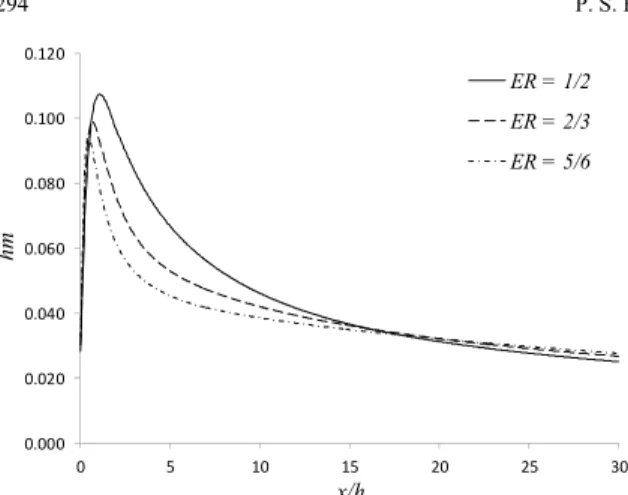
The effects of the expansion ratio (ER) on mass flux at the channel walls are presented in Figures 11 and 12. The results clearly indicate that the mass fluxes at both walls are reduced in the entry flow region (x/h < 15) with increasing expansion ratio ER. This behaviour may be explained due to the occur-rence of lower velocities in this region since the flow passage area was enhanced. Otherwise, the point of maximum value at the lower wall (see Figure 12) displaces towards the entrance section due to reduc-tion in the recirculareduc-tion region as the expansion ratio was increased (for the cases simulated x/s = 4, but as the step height s decreases, the vortex length also reduces – see Figures 13 and 14). Finally, in the flow region towards the exit section (x/h > 15) the results for the convective coefficient at the lower and upper walls are similar (with minor differences) for all expansion ratios (this is an expected result since the average velocities inside the channels are equal in this region).
0.000 0.020 0.040 0.060 0.080 0.100 0.120
0 5 10 15 20 25 30
hm
x/h
ER = 1/2
ER = 2/3
ER = 5/6
0.000 0.020 0.040 0.060 0.080 0.100 0.120
0 5 10 15 20 25 30
hm
x/h
ER = 1/2
ER = 2/3
ER = 5/6
Figure 12: Convective mass transfer coefficient for the lower wall in the channel with variable expansion ratios (ER).
Figure 13: Flow topology (streamlines) for the channel with expansion ratio ER = 2/3.
Figure 14: Flow topology (streamlines) for the channel with expansion ratio ER = 5/6.
CONCLUSIONS
In this paper a numerical method is presented for solution of the turbulent flow of a binary mixture inside channels. The numerical results obtained indi-cate that the scheme reproduced satisfactorily the literature data for both concentration profiles and Sherwood number. Furthermore, the numerical solu-tion obtained was clearly mesh independent.
Besides, in the physical analysis performed, the main conclusions are: (i) the parametric study reveals that distinct inlet flow velocities produce drastic
effects on the convective mass transfer coefficient. The analysis of the results clearly indicates that mass flux at the walls is highly enhanced as the inlet flow velocity varies from 6 to 12 (an average increase around 95%). Furthermore, the wall mass flux of the chemical species (water vapor) was enhanced in the entrance flow region (x/h<25) as the flow incidence angle increases. The physical scenario is dominated by the stagnation region formed at the channel upper wall, that leads to enhancement of the convective mass transfer process. (ii) The flow in a sudden ex-pansion reveals that the convective coefficient is very sensitive to the expansion ratio ER. In the entry flow region the mass flux reduces as the expansion ratio increases. Furthermore, the maximum value for mass flux near the reattachment point displaces to-wards the vertical wall as a consequence of the re-duction of the vortex zone.
NOMENCLATURE
A Jacobian matrices
 incidence angle [o]
As surface area [m2]
B Jacobian matrices
C average concentration of the chemical component [kg/m3]
i
C concentration of the chemical
component at the inlet [kg/m3] Cm bulk concentration [kg/m3]
w
C concentration of the chemical component at the walls [kg/m3]
C+ non-dimensional concentration [-]
cp specific heat coefficient [J/kgK]
cte constant [kg/s]
1, 2,
C C C turbulence model constants [-] DAB molecular diffusion coefficient of
chemical species A in B [m2/s] DABT turbulent diffusion coefficient of
chemical species A in B [m2/s] DABe effective diffusion coefficient of
chemical species A in B [m2/s]
Dh hydraulic diameter [m]
ER channel expansion ratio [-]
E, F Flux vectors
h channel height [m]
hm local convective mass transfer
coefficient [m/s] m
h average convective mass transfer
coefficient along the walls [m/s]
I identity matrix
Numerical Simulation of the Incompressible Turbulent Flow of a Binary Mixture of Air-Water Vapor: Applications in Drying Process 295
k molecular thermal conductivity [W/mK]
kT turbulent thermal conductivity [W/mK]
ke effective thermal conductivity [W/mK]
L channel length [m]
Lx, Ly left hand side operators
m mass flow [kg/s]
M time step
" w
No mass flux of the chemical species at the
walls [kg/m2s] e
p mean effective pressure [Pa]
PrT turbulent Prandtl number [-]
Q vector of conserved variables
Rx, Ry right hand side operators
ReDh Reynolds number based on the
hydraulic diameter [-]
S step height [m]
S source term
Sc molecular Schmidt number [-]
T
Sc turbulent Schmidt number [-]
Sh Sherwood number [-]
Sh average Sherwood number along the
channel length [-]
t time [s]
T average temperature [K]
Ti inlet temperature [K]
u* shear velocity [m/s]
i
u Cartesian components of the average velocity [m/s]
i
u inlet velocity [m/s]
um mean velocity in the channel cross
section [m/s] i
x Cartesian axis [m]
y+ non-dimensional distance from the wall
[-]
Greek Letters
,
k
turbulence model constants [-]
turbulent kinetic energy [m2/s2] i
turbulent kinetic energy at the inlet [m2/s2]
ε dissipation rate [m2/s3] ,
i e
coefficients of artificial dissipation [-]
μ dynamic viscosity [kg/ ms]
T
eddy viscosity [kg/ms]
e
effective viscosity [kg/ms]
ρ density [kg/m3]
Subscripts
e effective quantity
i inlet section and vector subscript
m average quantity
T turbulent quantity
REFERENCES
Arellano, J. S., Xáman, J., Álvarez, G. and Rivera, M. G., Heat and mass transfer by natural convection in a square cavity filled with mixture of air-CO2.
International Journal of Heat and Mass Transfer, 64, p. 725 (2013).
Arellano, J. S. and Rivera, M. G., Conjugate heat and mass transfer by natural convection in a square cavity filled with mixture of air-CO2.
Interna-tional Journal of Heat and Mass Transfer, 70, p. 103 (2014).
Arpaci, V. S., and Larsen, P. S., Convection Heat Transfer. Prentice-Hall Inc., New Jersey (1984). Beam, R. M. and Warming, R. F., An implicit
fac-tored scheme for the compressible Navier-Stokes equations. AIAA Journal, 16, p. 393 (1978). Incropera, F. P., Witt, D. P., Bergman, T. L. and
Lavine, A. S., Fundamentals of Heat and Mass Transfer. John Wiley & Sons, Inc., New Jersey (2007).
Kadem, S., Lachement, A., Younsi, R. and Kocaefe, D., 3d-Transient modeling of heat and mass trans-fer during heat treatment of wood. International Communications in Heat and Mass Transfer, 38, p. 717 (2011).
Kader, B. A., Temperature and concentration profiles in fully turbulent boundary layers. International Journal of Heat and Mass Transfer, 24, p. 1541 (1981).
Kays, W. M. and Crawford, M. E., Convective Heat and Mass Transfer. McGraw Hill Inc., New York (2005).
Launder, B. E. and Spalding, D. B., The numerical computation of turbulent flows. Computer Meth-ods in Applied Mechanics and Engineering, 3, p. 269 (1974).
Lamnatou, C., Papanicolaou, E., Belessiotis, V. and Kyriakis, N., Conjugate heat and mass transfer from a drying rectangular cylinder in confined air flow. Numerical Heat Transfer, Part A, 56, p. 379 (2009).
Lateb, M., Masson, C., Stathopoulos, T. and Bédard, C., Comparison of various types of models for pollutant emissions around a two-building configuration. Journal of Wind Engineering and Industrial Aerodynamics, 115, p. 9 (2013).
moisture transfer in a moist object subjected to convective drying, International Journal of Heat and Mass Transfer, 53, p. 4638 (2010).
Patankar, S. V., Numerical Heat Transfer and Fluid Flow. Hemisphere Pub. Co., New York (1980). Possamai, D. G., Análise numérica do escoamento
turbulento no interior de secadores Dissertação de Mestrado, CCT - UDESC, Joinville (2013). (In Portuguese).
Vaz Jr, M., Zdanski, P. S. B., Cerqueira, R. F. L. and Possamai, D. G., Conjugated heat and mass trans-fer in convective drying in compact wood kilns: A system approach. Advances in Mechanical Engi-neering, 2013, p. 1 (2013).
Xiong, J., Cheng, X., and Yang, Y., Numerical inves-tigation on mass transfer enhancement down-stream of an orifice. International Journal of Heat and Mass Transfer, 68, p. 366 (2014).
Younsi, R., Kocaefe, D., Poncsak, S., and Kocaefe, Y., Computational and experimental analysis of high temperature thermal treatment of wood based on ThermoWood technology. International
Communi-cations in Heat and Mass Transfer, 37, p. 21 (2010). Zdanski, P. S. B., Ortega, M. A. and Fico Júnior, N. G. C. R., Numerical simulation of the incompressible Navier-Stokes equations. Numerical Heat Transfer, Part B, 46, p. 549 (2004).
Zdanski, P. S. B., Vaz Jr, M. and Inácio, G. R., A finite volume approach to simulation of polymer melt flow in channels. Engineering Computations, 25, p. 233 (2008).
Zdanski, P. S. B. and Vaz Jr, M., A numerical method for simulation of incompressible three-dimensional Newtonian and non-Newtonian flows. Numerical Heat Transfer, Part B, 59, p. 360 (2011).
Zdanski, P. S. B., Possamai, D. G. and Vaz Jr, M., A numerical assessment of the air flow behavior in a convectional compact dry kiln. Journal of Applied Fluid Mechanics, 8, p. 367 (2015). Zdanski, P. S. B., Vaz Jr, M. and Gargioni, G. T.,