Potential of Vertical Line Array Beamforming
in Underwater Acoustic Communications
Salman Ijaz, Ant´onio J. Silva and S´ergio M. Jesus
Instituto de Sistemas e Rob´otica, Campus de Gambelas,
Universidade do Algarve,
8005-139, Faro, Portugal
Email:
{
ssiddiqui,asilva,sjesus
}
@ualg.pt
Resumo:
Um dos principais t´opicos atuais de pesquisa ´e a concepc¸˜ao de t´ecnicas de processamento de sinal eficazes para comunicac¸˜oes submarinas. Este interesse ´e reforc¸ado pelos desafios inerentes `as condic¸˜oes incontrol´aveis, como a batimetria, a temperatura, e as variac¸˜oes temporais (geom´etricas) das profundidades da fonte e da antena de receptores. A obtenc¸˜ao de taxas de transmiss˜ao modestas ´e ainda um desafio, devido a estas variac¸˜oes. O presente trabalho aborda o uso potencial do formador de feixes (beamformer) no sistema de comunicac¸˜oes submarinas. O prop´osito de usar um beamformer neste trabalho ´e o de separar os diferentes caminhos que chegam do transmissor para o recetor, o que ´e motivado pelo fato de que, num ambiente real, n˜ao ´e poss´ıvel distinguir todos os caminhos de propagac¸˜ao, no dom´ınio do tempo. Neste trabalho, ´e usado o beamformer de atraso-e-soma, que aplica atrasos diferentes para cada hidrofone da antena vertical, e adiciona as sa´ıdas resultantes. Cada um dos atrasos ´e func¸˜ao do ˆangulo de chegada e da profundidade do hidrofone. O objetivo do beamformer ´e aplicar os atrasos opostos a cada elemento da antena vertical, para garantir a soma coerente da frente de onda numa direc¸˜ao particular. Ambos resultados com dados simulados e dados reais s˜ao apresentados neste trabalho, para mostrar o desempenho do beamformer. Os resultados do beamformer s˜ao comparados com os resultados da an´alise Doppler, para caracterizar chegadas diferentes e fazer corresponder essas chegadas `as variac¸˜oes Doppler, mostrando que cada chegada ´e afetada pelas variac¸˜oes ambientais de uma maneira diferente, resultando numa quantidade diferente de Doppler.Palavras-chave:
Comunicac¸˜oes submarinas, antena vertical, formador de feixes, Efeitos DopplerAbstract:
One of the most active research topics nowadays is to design effective signal processing techniques for underwater communications. This interest is magnified by the challenges due to uncontrollable conditions such as temperature, bathymetry and geometric changes like source and array depth variations. The attainability of even modest data rates is still a challenge due to these variations. This work addresses the potential use of vertical line array beamforming for the underwater communication system. The purpose of using a beamformer in this work is to separate the different arriving paths from the transmitter to the receiver which is motivated by the fact that in real environment the arriving paths are merged into each other and it is not possible to separate them in time. In this work, the delay and sum beamformer is used, which applies different delays to each hydrophone of the vertical linearray and sums the resulting output. Each of this delay is a function of angle of arrival and depth of the hydrophone. The objective of a beamformer is to apply the opposite delays to each element of the vertical line array to guarantee coherent summation of the wavefront in a particular direction. Some simulated as well as real data results are presented in this paper to show the performance of the beamformer. These beamformer results are also compared with the Doppler results to characterize different arrivals and correspond these arrivals to the Doppler variations to show that each arrival is affected by the environmental variations in a different way, resulting in different amount of Doppler.
Keywords:
Underwater communications, Vertical line array, Beamforming, Doppler effects1. Introduction
Beamforming is a well known technique used in different underwater applications such as detection and localization of far-field sound sources [1], [2]. The main purpose of using beamforming techniques is to find the direction of arrival and to enhance the signal to noise ratio of the received signal. The beamforming technique was applied for underwater communications in [3] where a coherent path beamformer (CPB) is proposed for processing the signals using an adaptive processor that forms a beam in the direction of a collection of coherent signals representing the strongest path. In the direction of interference the processor forms null therefore canceling interference within the principal beam [4], [5]. In CPB only the strongest path is enhanced and nulls are placed in all the other paths thus ignoring the energy from the other paths, which is the major disadvantage of this technique.
This paper will demonstrate the potential of using VLA beamformer for underwater communication system. The idea is motivated by [6] where it was shown that each arrival is affected by different environmental variations and in order to compensate for these environmental effects efficiently it is necessary to separate each arrival and minimize the effects of these variations on each arrival separately. In this paper a delay and sum beamformer is presented which applies opposite delays to the received signals to guarantee coherent summation of the received signal. A simulated and a real data result is presented in this paper to show the performance of the VLA beamformer. The results from the VLA beamformer are also compared with the Doppler observation from [6] to show that each arrival (which is characterized by the angle of arrival by the VLA beamformer) experiences different amount of Doppler due to different environmental variations.
The paper is organized as follows: Section I will explain the implementation of the VLA beamformer. Section II will present some results from the simulated data and also some real data results and section III will give the conclusion of the paper and some future work.
2. The Vertical Line Array Beamformer
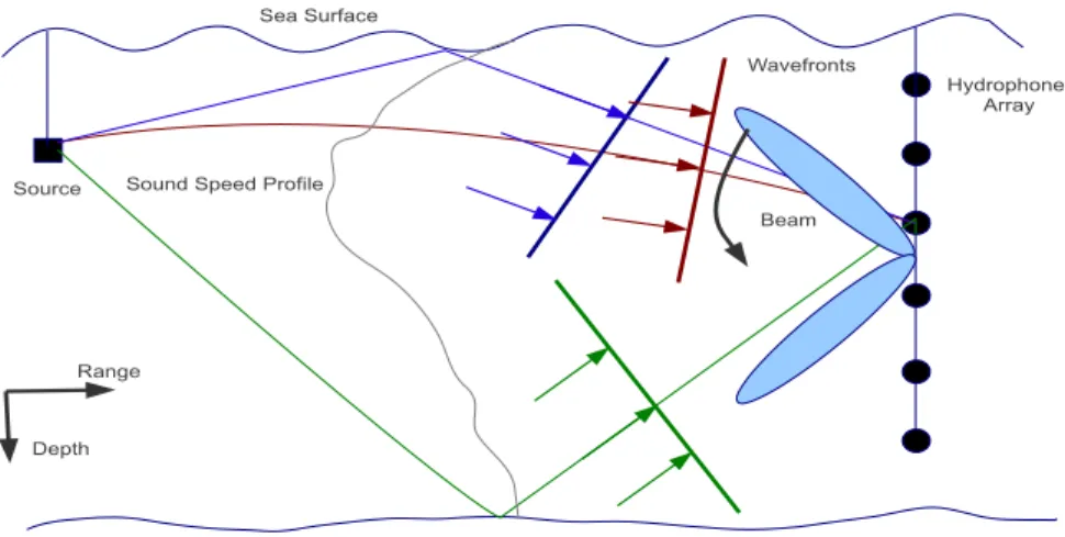
Figure 1 shows the basic underwater scenario where the wave propagation depends on two spatial variables, range ‘r’ and depth ‘z’. Any arbitrary location in the scenario can be represented by location ‘(r, z)’ in the range-depth plane. In figure 1 the source location is considered to be the point of reference which is (0, zs), and the hydrophone array is located at
the distance r0 from the source. Thus the location of each hydrophone in the array becomes
(r0, z1), (r0, z2), ...(r0, zI) where I is the number of hydrophones in the array. The grey line
Sound Speed Profile Source Sea Surface Hydrophone Array Range Depth Wavefronts Beam
Fig. 1. Basic underwater Scenario showing the source,receiver and different arrivals from the source to the receiver. The VLA beamformer is implemented on the receiver to isolate different arrivals depending on the angle of arrival, by steering the beam along the water column
temperature, salinity and pressure where pressure is a function of depth. It defines the behaviour of the propagation of sound in the underwater medium. The attenuation experienced by the sound depends on the distance travelled, and the number of reflections from the bottom and the surface.
In figure 1 different arrivals are also shown from the source to the array. The direct arrival (shown in red colour) is the one without any surface or bottom interaction so it is only affected by the source and array movement and sound speed profile variations. The surface reflected arrival (shown in purple) is also affected by surface variations in addition to the above mentioned variations. The bottom reflected arrival (shown in green) is mainly affected by the bottom properties which are specified as density, compressional speed and attenuation. This is a simplified diagram showing only the single reflected arrivals while in real environment there are several other arrivals which reaches the receiver after many surface and bottom reflections. Figure 1 also shows the plane wavefronts associated with these paths, arriving to the VLA and it can be seen that all the wavefronts have different arrival angles thus they arrive at different hydrophones with different delays.
It is assumed in this work that the source and the receiver justifies the far field condition such that the signals are received in the form of plane wavefronts at the receiver. The basic purpose of employing the beamforming is to spatially filter the space-time field such that the signal from a particular angle is enhanced by constructive combination and signals from other set of angles are rejected by destructive interference.
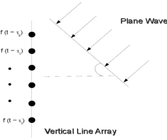
Figure 2 simplifies figure 1 showing only a single wavefront reaching the VLA. From the figure it can be seen that the plane wavefront arrives at the each hydrophones of the array with different delays. Let zi be the depth of each hydrophone in the VLA where i is the hydrophone
index and i = 1, 2, 3, ...I, then the set of received signals at each hydrophone of the array is represented by f (t, z) = f (t − τ0) f (t − τ1) .. . f (t − τI) (1)
where τi represents the delay with which the signal is received at each hydrophone i of the
array. It should be noted that the delay encountered by each hydrophone of the VLA is a function of the depth zi and the angle of arrival θk at each hydrophone. The objective of
Fig. 2. Plane wavefront arriving at each element of the array with different delays
(a) (b)
Fig. 3. Time and frequency domain implementations of the beamformer
the beamformer is to apply opposite delays τi to each hydrophone i of the VLA in order to
guarantee a coherent sumation of the wavefronts in a particular direction.
This is shown in a block diagram in figure 3 (a). In the block diagram θk is the same for
all the hydrophones as it corresponds to the angle of the beam which will be same for all the hydrophones. However θk generates different delays in each hydrophone due to their
different depths resulting τ (zi, θk) ≡ τi(θk). In the frequency domain the beamformer can be
implemented by applying a phase shift to the signal which is done by multiplying an exponential as shown in figure 3 (b). This multiplication of exponential is equivalent to applying a delay in the time domain. In this work the frequency domain implementation of the beamformer is used.
3. Results and Observations
(a) (b)
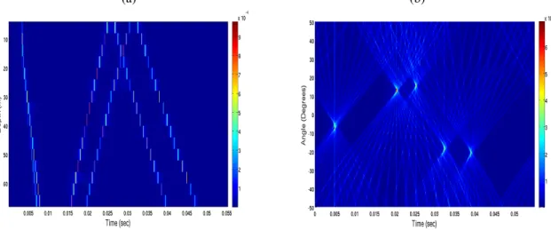
Fig. 4. Simulated channel characterization: a) Channel IR estimates b) The beamforming result showing the angle of arrival of different arrivals
data. In the first part of this section a simulated scenario is presented and in the later part of this section real data results are shown.
3.1 Simulated Data Results
In order to simulate the underwater environment, the Time Variable Acoustic Propagation Model (TV-APM) was used, which was proposed in [7]. For the simulated case a source-receiver range is 1 km and a source is placed at 12 m depth. A 16 hydrophones VLA is considered with the first hydrophone placed at 6 m depth and an interspacing between the hydrophones of 4 m. A flat surface is considered in TV-APM for this case.
In the first case the source is considered to be moving only along vertical direction with the velocity of 0.5 m/sec. Figure 4 (a) shows the arriving pattern of the channel. It can be seen that there are six wavefronts arriving at the VLA. Figure 4 (b) shows the beamformer result where all six wavefronts can be seen in the angle delay-spread plane. The negative angles shows the wavefronts from the bottom while the positive angles shows the wavefronts from the surface. Figure 4 completely characterizes all the wavefronts. Figure 4 (a) shows that the initial wavefronts are the top arrivals as they have negative slope while the third and the fourth wavefronts are the bottom arrivals as they have positive slope. These observations are confirmed by figure 4 (b) where it can be seen that the initial wavefronts have negative angle while the third and the fourth wavefronts have positive angle of arrival.
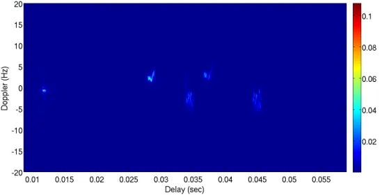
Figure 5 shows the Doppler spectrum of the channel at hydrophone 6 which is placed at 26 m depth. The source is moving only in the vertical direction so the values of Doppler for all wavefronts are very small. The Doppler value of the first wavefront which is considered to be the direct arrival is approximately -1 Hz. This small value of Doppler can be explained using equation (2) which is presented [6].
φ02 = ((VT − VS) · ˆn
00
T − (VS− VR) · ˆn00R)/c
(1 − VS· ˆn00R/c)(1 − VT · ˆn00T/c)
fc (2)
Equation (2) shows that the Doppler value φ is related with the inner product of the relative velocities of the source VT and the receiver VR. As the source is moving in the vertical direction
the inner product gives very small value resulting in a small value of Doppler.
Fig. 5. Doppler spread, at hydrophone 6 placed at 26 m depth, due to a source vertical motion of 0.5 m/s
ways thus each arrival have different values of Doppler due to the same environmentally affected variation. Such behavior can be clearly seen in figure 5 where the source motion in the vertical direction generates a small Doppler for the first two arrivals and a strong Doppler for the latter arrivals.
3.2 Real Data Results
The data set shown in this section was collected during the UAB’07 experiment. During the experiment the source was suspended by a crane from a fixed platform, 10 m from shore, at an initial depth of 5 m. The receiver was a vertical array with 16 hydrophones uniformly spaced at 4 m between 6 m to 66 m depth. The communication range was approximately 1 km with the water column depth of 12 m at source location and about 120 m at array location. Figure 6 shows the zoomed version of the IR estimate. It can be seen clearly that there are a large number of arrivals reaching the receiver. Figure 7 shows the angle of arrivals of different
Fig. 7. The beamforming result showing the angle of arrival of different arrivals
arrivals. It can be seen that there are two strong arrivals at approximately 3 degree and the third and fourth arrival at approximately 0 degree. Also there is another arrival at approximately -30 degree.
In the arriving pattern, shown in figure 6 the later arrivals are very unstructured and it is very difficult to differentiate between different arrivals but the beamforming results in figure 7 differentiate between different arrivals. In the arriving pattern, there is an arrival at approximately 0.01 sec (the one at 0o) which is almost vertical which means that it arrives at all hydrophone
at the same time. This is an abnormal behavior for a later arrival as these arrivals are usually bottom or top reflected arrivals and they reach all the hydrophones of the array with different delays. The probable reason for this behavior is that there may be a tilt in the hydrophone array due to the currents and thus all the hydrophones received the wavefront at almost the same time.
4. Conclusions and future work
This paper presented the vertical line array (VLA) beamforming technique for seperating the arrivals from the transmitter to the receiver based on the angle of arrival. In this work a delay and sum beamfomer was presented which applies different delays to each element of the VLA to guarantee coherent summation of the wavefronts. The simulated data as well as real data results have shown that it is much easier to separate the arrivals on the basis of angle of arrivals using the VLA beamformer.
The future work will address some techniques to minimize the effects of environmental variations on each arrival separately. It was shown in [6] that each arrival is affected by different environmental variations which induces different amount of Doppler in each arrival. By using this observation and using VLA beamforming for seperating each arrival it is possible to address different arrivals separately. The idea will be to propose an arrival based equalizer which will equalize each arrival separately and compensate for the environmental variations in a more efficient way.
REFERENCES
[2] J. Billingsley and R. Kinns. The acoustic telescope. J. Sound Vib., 48:485–510, 1976.
[3] L. R. LeBlanc and P. P Beaujean. Underwater communication in shallow water. Oceanology 98, Brighton, UK, 2:209–221, 1998. [4] L. LeBlanc. Angular-spectral decomposition beamforming for acoustic arrays. Oceanic Engineering, IEEE Journal of, 9(1):31 – 39, jan
1984.
[5] Lester R. LeBlanc and John I. Salisbury. High resolution wavenumber-frequency methods for towed arrays. The Journal of the Acoustical Society of America, 90(6):3155–3160, 1991.
[6] S. Ijaz; A.J. Silva ; O.C. Rodriguez ; S.M. Jesus ;. Doppler domain decomposition of the underwater acoustic channel response. In OCEANS 2011 IEEE Conference, Santandar, Spain, pages 1–7, June 2011.
[7] A. Silva, O. Rodriguez, F. Zabel, J. Huilery, and S. M. Jesus. Underwater acoustics simulations with time variable acoustics propagation model. Proceeding of 10th European Conference on Underwater Acoustics, 2:989–996, July. 2010.