Energy Tunneling Through Narrow Waveguide
Channel and Design of Small Antennas*
Miranda Mitrovi
ć
1, Branka Jokanovi
ć
1Abstract: In this paper we investigate the conditions for energy tunneling through narrow channel obtained by reducing the height of rectangular waveguide. Tunneling of the energy occurs at the frequency for which the effective dielectric permittivity of the channel becomes equal to zero, so it can be treated as an ENZ (epsilon-near-zero) metamaterial. We investigated how geometry of the channel and dielectric permittivity affect the transmission coefficient and field density in the channel. Adding slots in the channel, which are placed orthogonally to the wave propagation, we designed a small antenna with directivity of 5.44 dBi at the frequency of 3 GHz.
Keywords: ENZ metamaterial, Zeroth-order resonance, Fabry-Perot resonance, High-directivity antenna.
1 Introduction
During the last decade there has been a great interest in metamaterials whose relative dielectric permittivity εr is close to zero (epsilon-near-zero, ENZ metamaterials). This kind of metamaterials can be designed using standard techniques, like split-ring resonators [1], however dispersion characteristic of rectangular waveguide near the cut-off frequency can also be used to mimic the behaviour of ENZ metamaterial [2]. There can be a number of applications for this structure, from cloaking devices [3], confining energy beyond diffraction limit, and waveguide coupling through very narrow channel without energy loss, to designing small, and high-directivity antennas.
2 Theoretical
Analysis
Rectangular waveguide with width a and height b (where a>b) can support propagation of TE and TM modes. The mode cut-off frequency is determined by expression:
1Institute of Physics Belgrade, Pregrevica 118, 11080 Belgrade, Serbia; E-mails: [email protected];
2 2
( , ) ,
2
c m n
r
c m n
f
a b
π π
⎛ ⎞ ⎛ ⎞
= ⎜ ⎟ +⎜ ⎟
π ε ⎝ ⎠ ⎝ ⎠ (1)
where εr is relative dielectric permittivity of the material filling the waveguide.
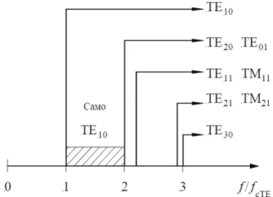
Fig. 1 –The sequence of modes in rectangular waveguide with heightb = a/2.
It can be seen clearly from Fig. 1 that dominant mode in rectangular waveguide is TE10, while the next mode is TE20. Frequency range between cut-off frequencies of those two modes is marked as a pass band of rectangular waveguide. It is important to emphasize that cut-off frequencies of TE10 and TE20 modes do not depend on b since n=0. But, if we reduce the height of rectangular waveguide b, the cut-off frequencies for higher modes for which
0
n≠ , will shift toward higher frequencies.
If we start to reduce the height of rectangular waveguide continuously (Fig. 2), it is intuitively obvious that at one point the reflection coefficient will considerably grow and stop propagation of energy through the very narrow channel.
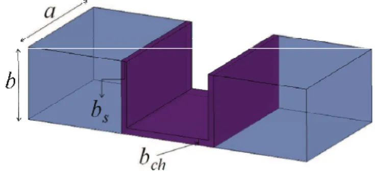
If instead of configuration in Fig. 2 we use the structure shown in Fig. 3 with Π-channel, transmission will be possible in the narrow frequency band as long as dielectric permittivity of material filling the channel is smaller than in input waveguides. Later on, the explanation of this phenomena will be provided.
Fig. 3 – Waveguide with narrow Π-channel (bch<< b).
According to [2], it is possible to consider propagation of TE10 mode in a narrow rectangular waveguide as propagation of TEM mode in a parallel plate waveguide with effective permittivity εreff:
2 2 10 2 , reff TE TEM f k a c π ε π ⎛ ⎞
β = −⎜ ⎟ = β =
⎝ ⎠ (2)
where 2 . r r f k c
π μ ε =
The effective permittivity of the channel can be derived as: 2
2 2. 4
reff r
c f a
ε = ε − (3)
Here c is the speed of light in vacuum, and εr is dielectric permittivity of the channel. It can be easily seen that εreff equals to zero at the cut-off
frequency of the channel: fc(10) =c 2a εr . This explains why we can consider this structure as an ENZ metamaterial around frequency fc(10).
account that εreff in the channel is near zero close to cut-off frequency, which is
not equal to zero, we come to conclusion that wave vector β is also closed to zero and wavelength approaches infinity. This kind of behaviour is characteristic for balanced left-handed (LH) metamaterials that have the zeroth-order frequency (ZOR) [6] at the transition between left- and right-handed regions. At that frequency β is equal to zero. Energy transfer through the channel at ZOR frequency is obtained with relatively small losses. Also, field is constant along the channel and field density is a very large and proportional to waveguide/channel height ratio.
3
Simulation Results for ENZ Channel
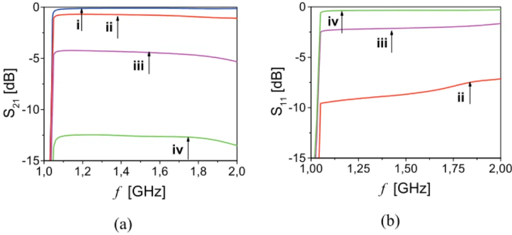
We considered firstly, the structure from Fig. 2 with waveguide width and height a = 101.6 mm and b = a/2 = 50.4 mm. Since dielectric permittivity in the input waveguides is ε =r 2, cut-off frequency for TE10 mode is 1.044 GHz, and for TE20 mode 2.088 GHz. Values for the channel height are chosen to be:
bch1 = b, bch2 = b/2=25.4 mm, bch3 = b/8 = 6.35 mm and bch4 = b/64 = 0.8mm. Simulation results for transmission and reflection coefficients are shown in Figs. 4a and 4b respectively.
1,0 1,2 1,4 1,6 1,8 2,0 -15 -10 -5 0 i ii iii iv
f [GHz]
S21
[dB]
(a)
1,00 1,25 1,50 1,75 2,00
-15 -10 -5 0 iv iii ii
f [GHz]
S11
[d
B]
(b)
Fig. 4 – Transmission (a) and reflection coefficients (b) for different values of bch: (i) bch1 = b = 50.8 mm, (ii) bch2 = =25.4 mm, (iii) bch3 = 6.35 mm; (iv) bch4 = 0.8 mm.
1,25 1,50 1,75 2,00 -30
-25 -20 -15 -10 -5 0
f [GHz]
S 21
[d
B]
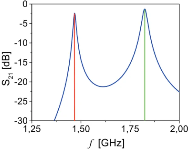
Fig. 5 – Transmission coefficient for Π-channel for bs = bch = 0.8 mm.
To compensate the influence of discontinuity at the channel/waveguide junctions, we added two transition layers with thickness bs = bch, which form
Π-channel, as it is shown in Fig. 3 (values of a and b are the same as before). Dielectric permittivity of the channel and transition area is ε =rch 1 (air), and of input waveguides ε =r 2. Transmission coefficient for Π-channel with
bs = bch = 0.8 mm is shown in Fig. 5. It can be seen that the first transmission
peak appears at 1.476 GHz and represents the zeroth-order resonance, ZOR. That is actually the frequency at which the energy tunnelling is appeared, since the effective permittivity is equal to zero. The second transmission peak is due to Fabry-Perot resonance and its position strongly depend on the channel length, which is not the case for ZOR, as long as bch << a [7].
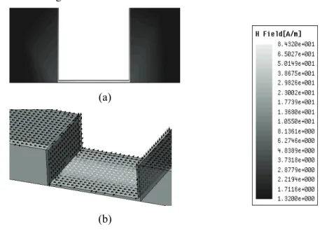
The field distribution in ENZ channel and real part of Poynting vector are shown in Figs. 6a and 6b respectively.
In approximation of perfectly conducting metallic walls and lossless dielectrics, field density in the channel is increased with reduction of channel height and transmission is perfect. In reality, field density in channel is restricted by break down voltage in dielectric and transmission is lowered due to finite conductivity of metallic walls and dielectric losses. Simulated results for
bch1 = b/16 = 3.18 mm and bch2 = b/64 = 0.8 mm are shown in Fig. 7. Metal used is copper with σ = 58 MS/m. Detailed discussion on losses in ENZ channel is given in our previous work [8].
energy is occurred. Change of Fabry-Perot resonance for various lengths of a narrow channel (bch = b/64 = 0.8 mm, L1 = 95.25 mm, L2 = 127 mm and
L3 = 190.5 mm)can be seen in Fig. 8. This property can be used to manipulate the second transmission peak in order to remove it or leave it within the pass band of the waveguide.
(a)
(b)
Fig. 6 – (a) Field distribution in a narrow channel shows H-field density inside the channel enhanced by factor b/bch in comparison to
field in waveguide sections; field density is constant along the channel; (b) Real part of Poynting vector shows energy flow through the channel; energy is concentrated in the middle of the channel and gradually descending toward edges.
1,00 1,25 1,50 1,75 2,00
-30 -25 -20 -15 -10 -5 0
ii i
f [GHz]
S21
[d
B
]
1,25 1,50 1,75 2,00 -30
-25 -20 -15 -10 -5 0
iii ii
i
f [GHz]
S21
[dB]
Fig. 8 – Shifting the second transmission peak (Fabry-Perot resonance) due to variation of channel length:
(i) L1 = 95.25 mm, (ii) L2 = 127 mm, (iii) L3 = 190.5 mm.
4
Antenna Design and Simulation Results
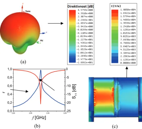
Using ENZ channel, simple antenna can be designed by placing one or few slots on the top or bottom side of ENZ channel along or normal to the direction of propagation. If the slots are oriented along the propagation direction they should be placed at a certain distance from the middle of the channel in order to get noticeable radiation. Much higher radiation can be achieved if the slots are perpendicular to the direction of wave propagation. Simulated radiation pattern for two slots placed symmetrically around the middle of the channel and perpendicular to the direction of propagation are given below. Channel dimension is 50×50 mm, slots dimensions are 1×50 mm, and the distance between them is 3 mm.
The main drawback of this antenna is that it operates in very narrow frequency range, as can be seen in Fig. 9b. The level of radiation here is shown
through the value of ρ = S112− S212 since designed antenna is a progressive wave antenna.
Radiation patterns with respect to φ and θ are given in Figs. 10a and 10b. It can be seen that this antenna has following 3dB-beamwidths: θH3dB = 139.7° and
(a)
2,90 2,95 3,00 3,05
0,0 0,2 0,4 0,6 0,8 1,0
f [GHz]
r
-25 -20 -15 -10 -5 0
S
11
[dB]
(b) (c)
Fig. 9 – (a) 3D radiation pattern; (b) Radiated power and reflection coefficient; (c) E-field in configuration with two radiating slots in the middle of the channel.
(a) (b)
6 Conclusion
In this paper we investigate how geometry parameters of the ENZ channel influence the energy tunneling through the channel. If the channel height is getting smaller, the energy confining is increased, as well as the reflection and losses, while the frequency range in which tunneling occurs becomes narrower. Changing the channel length affects only the position of Fabry-Perot transmission peak, while there is no influence to ZOR resonance. ENZ channel is used in design of a small, high-directivity antenna which consists of two vertical slots, perpendicular to wave propagation.
7 References
[1] R. Liu, Q. Cheng, T. Hand, J.J. Mock, T.J. Cui, S.A. Cummer, D.R. Smith: Experimental Demonstration of Electromagnetic Tunneling through an Epsilon-near-zero Metamaterial at Microwave Frequencies, Physical Review Letters, Vol. 100, No. 2, Jan. 2008, 023903. [2] B. Edwards, A. Alù, M.E. Young, M.G. Silveirinha, N. Engheta: Experimental Verification
of Epsilon-near-zero Metamaterial Coupling and Energy Squeezing using a Microwave Waveguide, Physical Review Letters, Vol. 100, No. 3, Jan. 2008, 033903.
[3] M.G. Silveirinha, A. Alù, N. Engheta: Parallel-plate Metamaterials for Cloaking Structures, Physical Review E, Vol. 75, N. 3, March 2007, 036603.
[4] M.G. Silveirinha, N. Engheta: Tunneling of Electromagnetic Energy through Subwave-length Channels and Bends using ε-near-zero Materials, Physical Review Letters, Vol. 97, Vol. 15, Oct. 2006, 157403.
[5] S. Enoch, G. Tayeb, P. Sabouroux, N. Guérin, P. Vincent: A Metamaterial for Directive Emission, Physical Review Letters, Vol. 89, No. 21, Nov. 2002, 213902.
[6] C. Caloz, T. Itoh: Electromagnetic Metamaterials: Transmission Line Theory and Micro-wave Applications, John Wiley and Sons, NJ, 2006.
[7] M.G. Silveirinha, N. Engheta: Theory of Supercoupling, Squeezing Wave Energy, and Field Confinement in Narrow Channels and Tight Bends using ε-near-zero Metamaterials, Physical Review B, Vol. 76, No. 24, Dec. 2007, 245109.