Dynamic compressive behavior in different loading directions of 3D
braided composites with different braiding angle
Abstract
Dynamic compressive tests of 3D braided composites with different braid-ing angle were carried out in the longitudinal, transverse and thickness di-rections respectively using the Split Hopkinson pressure bar (SHPB). The results show that the compressive properties present obvious strain rate strengthening effects in all directions. The 20° and 45° braided composite are most sensitive to strain rates in the longitudinal direction. The compo-sites present the features of brittle failure at high strain rates, especially in the longitudinal direction. The composites with larger braiding angle have weaker mechanical properties in the longitudinal and transverse directions but stronger mechanical properties in the through-thickness direction. The braid angle has the greatest impact on the longitudinal mechanical proper-ties. The compressive stress-strain curves in the thickness direction were similar to the hysteresis curve for both the 30° and 45° braided composites. The compressive failure modes vary with the loading directions and strain rate.
Keywords
3D braided composites; dynamic compression; strain rate effect; braiding angle; loading direction; microscopic damage.
1 INTRODUCTION
Three-dimensional (3D) braided composites is an promising composite material (Mouritz et al., 1999), which have been widely employed in aviation applications due to its high interlaminar shear strength and excel-lent impact resistance (Kamiya et al.,2000; Bilisik, 2013). As 3D braided composites have complex architecture preform, its mechanical behavior is affected by constituent fiber and matrix properties and fractions and braiding angle (Huang, 2016). Many researchers have conducted study on the internal configuration and relative cross section assumption (Fang, et al. 2009; Li, et al. 2010), the elastic properties and strengths prediction and failure analysis of the braided composites. Different experimental, analytical, and numerical methods were employed (Ge et al. 2018; Li et al. 2014; Zhang et al. 2015; Fan et al. 2015; Wang et al. 2018).
The dynamic responses of 3D braided composites under high velocity impact is extremely important when it encounter impact conditions such as FOD, bird/ice impact or blade out event as the aircraft or aeroengine struc-tural component instead of metal material for weight savings. Although its mechanical properties have been wide-ly investigated, few studies were conducted on its impact behavior. To study the impact resistance and failure modes of 3D braided composites, ballistic impact tests were generally conducted by researchers. Gong and Sankar (1991) performed impact experiments on 3D braided composites and compared its damage pattern and impact resistance with quasi-isotropic laminates. Tests results indicate that 3D braided composites have better damage tolerance than laminates with in spite of similar bending stiffness. Flanagan et al. (1999) conducted ballistic im-pact tests to compare the imim-pact resistance and failure modes of textile composites with different construction, including woven, 3D braided, and needle-punched composites. Tang , Yan, Chen, et al. (2001) indicate the primary damage is bundle interface cracking and intra-bundle delamination at the bundle crimping locations while the failure modes were mainly fiber/matrix debonding, delamination and matrix cracking propagation. Xu and Gu (2002) state that the major high velocity impact failure modes of 3D braided composites are shear and compres-sion failure in the impact surface but extensive tencompres-sion failure in the exit surface. Jenq and Mo (1996), Jenq et al. (1998) conducted ballistic impact tests with velocities 70~170 m/s, and found the major impact damage pattern is indentation, matrix failure, fiber breakage, and axial and braider yarn pulled out. Zhou et al. (2016, 2018)
de-Zhenhua ZHAOa
Lulu LIUa
Wei CHENa*
Xiong HUANGa
a Jiangsu Province Key Laboratory of Aerospace Power
System, College of Energy and Power Engineering, Nanjing University of Aeronautics and Astronautics, Nanjing, China. E-mail: [email protected], [email protected], [email protected], [email protected]
*Corresponding author
http://dx.doi.org/10.1590/1679-78255111
scribed the transverse impact damage mechanisms of 3D circular braided composite tubes and discussed the effects of impact velocity, braided angle and the braiding layers number. Zhang et al. (2012) presented the trans-verse impact results of 4-step 3D braided composite and pointed out that the failure area is in a zigzag shape due to the braided fiber tows breakage. Because conducting ballistic impact tests are usually restricted by device abil-ity, and always consume a large number of money and time. Therefore, numerical methods is become more and more preferred to investigate the dynamic response of 3D braided composites, which also helps the process of structures design and optimization (Zhang et al. 2017; Zheng et al. 2011).
To analyze the impact behavior of 3D braided composites require to describe the dynamic mechanical behav-iors in high strain rate (101/s–104/s) of 3D braided composites. Recently, some scholars have conducted relative
studies on dynamic behaviors of 3D braided composites. The compressive properties of 3D braided composites were studied more extensively than tensile and shear properties. Generally, the uniaxial tensile modulus, maxi-mum tensile stress of 3D braided composites increased with the strain rate almost linearly (Gan et al. 2012; Sun et al.2005;). Li et al. (2017,2016) conducted dynamic shear tests on 3D braided composites and investigated the influences of braiding parameters on the shear failure modes. Multiple damage modes including fiber tows frac-ture, fiber/matrix debonding, matrix cracks and inter-yarn delaminations were observed under shear loading.
Although various numerical methods based on finite element model in different scale (Zhang et al. 2014a; Wan et al. 2015; Fang et al.2011) have been developed to be more mature, the experimental methods using Split Hopkinson Pressure Bar (SHPB) still play the major role in most research on dynamic behavior of 3D braided composites. Sun and Gu (2007a, 2007b) studied out-plane and in-plane compressive and uniaxial tensile behavior of 4-step 3D braided composites at high strain rates through experiments. The mechanical properties of 3D braid-ed composite materials are strain rate sensitive. Both the failure stress and compressive stiffness increase with strain rate. The 3D 5-directional braided composites were also tested to obtain its uniaxial compressive behavior at strain rates ranging from 350 s-1 to 1600 s-1 (Wang et al., 2010). The energy absorption also increases with
strain rate, corresponding to the different damage mechanisms with quasi-static compression (Gu and Chang, 2007). Similarly, Li et al. (2011, 2009) reported the strain rate strengthening effects of 3D braided composites under longitudinal and transverse compression. For the past few years, the high strain rate compressive proper-ties of 3D braided composites at low temperature (Pan et al., 2015) and high temperatures (Song et al., 2014) were investigated respectively.
Although the current research indicating the influences of strain rate on the compressive properties of 3D braided composites in terms of certain braiding angle and loading direction, there are limited research on the influence of both loading direction and braiding angle. In this paper, the effect of loading direction and braiding angle on the dynamic compressive behaviors of 4-step 3D braided carbon fiber/epoxy composites at strain rates ranging from 800 s-1 to 2000 s-1 was studied experimentally through SHPB apparatus. The compressive
stress-strain curves, compressive modulus, failure stress/stress-strain and the energy absorption of 3D braided composites at the longitudinal, transverse and thickness directions were obtained and compared.
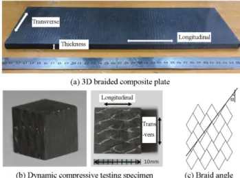
2 SHPB testing methods 2.1 Materials and specimen
Figure 1: Dynamic compression test specimen made of 3D four-step braid composites and sketch of braid angle of the composites.
2.2 Dynamic compressive testing
The dynamic compression tests were carried out on a Split Hopkinson Pressure Bar (SHPB), as shown in Fig-ure 2. The dynamic test is conducted on an SHPB system with bars of diameter 14.5 mm. The length of striker bar, incident bar, and transmission bar are 40 mm, 150 mm and 10 mm, respectively. To match the impedance re-sistance with that of the composite material, high strength steel is chosen for the bar material (Song et al. 2014). The incident, reflected and transmitted wave measured with strain gage are recorded by the high dynamic strain indicator in terms of voltages, which are converted into εi, εr and εt. Particularly, to observe the dynamic fracture process of 3D braided composites, one high speed camera (HX-3E type, NAC) were placed in front of the testing specimen. The frame frequency is chosen as 24940 photos per second. The typical stress wave obtained in the experiment is shown in Figure 3. The engineering stress (
s), strain (
s) and strain rate (
s) in the specimen can be calculated based on one-dimensional stress wave theory by the strain measure in the incident bar and transmission bar:( )
(
)
2
b bs i r t
s
A E
t
A
(1)0
( )
b t(
)
s i r t
s
c
t
dt
l
(2)( )
b(
)
s i r t
s
c
t
l
(3)And b
b b
E
c
(4)Where
i is the strain signal of the incident pulse,
r is the strain signal of the reflected pulse, and
t is the strain signal of the transmitted pulses; ls is the sample length, Ab and As are the cross-section area of the bars andspecimen, Cb, ρb, and Eb are uniaxial elastic stress wave speed in pressure bars, density and Young’s modulus of
Figure 2: Split Hopkinson pressure bar system setup.
Figure 3: Typical waveforms in dynamic compression test of composites.
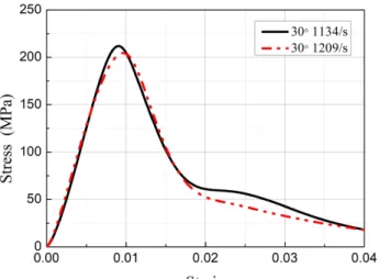
For the 3D braided composite samples in this paper, there are three directions of loading, namely longitudi-nal, transverse, and thickness directions. The definition of the loading direction is illustrated in Figure1. To unify the strain-rate ranges of 3D braided composite samples of different braiding angle in different loading direction, the same gas pressure were used for dynamic compression testing. Each direction of the specimen with different strain rates has been tested three times to verify the reliability of the experimental results. Only in case the three results agree with each other well (as shown in figure 4), it could be considered correct and used to be studied.
3 Dynamic compression behavior of 3D braided composites
The dynamic compression tests in the longitudinal, transverse and through-thickness directions were carried out on 20°, 30° and 45° braided composites respectively with the launch pressures of 0.4 Mpa, 0.6 Mpa, 0.3 Mpa and 1.0 MPa. Each test was repeated three times under every launch pressure. The dynamic compressive test results were used to figure out the effect of strain rate, loading direction and braiding angle on the dynamic me-chanical properties and failure modes.
3.1. Longitudinal compression behavior
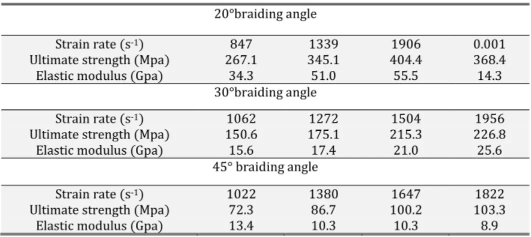
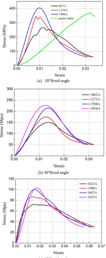
The results of longitudinal SHPB tests results for 3D braided composites of different braiding angle are shown in Table 1. The longitudinal compression stress-strain curves are shown in Figure 5 for different braiding angle respectively while the longitudinal compression failure morphology in different strain rate are shown in Figure 6.
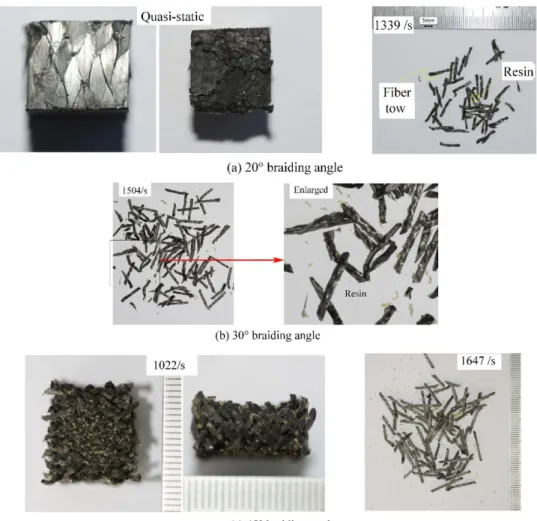
From Table 1, it can be seen that the ultimate strength and elastic modulus of 20° braided angle composites increased greatly compared with the value at the quasi-static strain rate, indicating that the composites is quite sensitive to strain rate under longitudinal compression. The ultimate strength at the quasi-static strain rate was between 1339/s and 1906/s, and the elastic modulus was significantly lower than that at high strain rates. This is because under the quasi-static compression, due to the slow loading, the material had enough time to adjust to the increase of strain. It can be seen that the failure strain of the composites under a quasi-static state is obviously greater than that of the materials at the high strain rate. The ultimate strength at the quasi-static state was obvi-ously higher than that at the strain rate 847/s, which was close to the value at high strain rates after reinforce-ment, whereas the stiffness is significantly worse than that at high strain rates. The results of 30° braid angle are similar to that of 20° braid angle. With the increase of strain rate, the ultimate strength and elastic modulus of the composites both increased, but the strengthening effect of strain rate become unapparent when the strain rate exceeded 1500/s. For the 45° braid angle, as the strain rate increased, the ultimate strength of the material in-creased and the elastic modulus dein-creased slightly. Under the 30° longitudinal compression, the testing specimen was completely ruptured and the matrix was separated from the fiber bundles, producing a bundle of black fiber bundles and light yellow resin particles. In contrast, the 45° braid angle testing specimens were not fully crushed under the longitudinal compression, as shown in Figure 6 (c). When the strain rate was 1022/s, the testing spec-imens were pressed flat and the fiber bundles were interlaced, with crushed resin particles filling between the gaps. Under the other three strain rates, the testing specimens were completely broken, where the matrix and the fiber bundle were split up, and fiber bundles were also separated from each other.
Table 1: Longitudinal compression properties of composites at different strain rates.
20°braiding angle
Strain rate (s-1) 847 1339 1906 0.001
Ultimate strength (Mpa) 267.1 345.1 404.4 368.4
Elastic modulus (Gpa) 34.3 51.0 55.5 14.3
30°braiding angle
Strain rate (s-1) 1062 1272 1504 1956
Ultimate strength (Mpa) 150.6 175.1 215.3 226.8
Elastic modulus (Gpa) 15.6 17.4 21.0 25.6
45° braiding angle
Strain rate (s-1) 1022 1380 1647 1822
Ultimate strength (Mpa) 72.3 86.7 100.2 103.3
Figure 6: Failure modes of composites with different braid angles under longitudinal compression at different strain rates.
Figure 7 shows the failure modes of the 20° braided angle composites as the testing specimen at the strain rate 847/s photographed by a high-speed camera. The first six of these pictures were taken during the spreading process of the first stress wave, while the last two were taken near the final destructive form. It can be seen that under the influence of the first stress wave, both ends of the testing specimen were crushed, and then the crack expanded rapidly to the middle. Soon the entire testing specimen ruptured along the longitudinal direction, the surface was broken into many small pieces, the fiber bundles and the matrix were separated. Under the dynamic compression, the testing specimen was completely broken, while under the quasi-static compression, the surface of the testing specimen was cracked but its overall shape remained intact, indicating that the material is more brittle at the high-strain rate. The comparison on the morphologies of the testing specimens under the quasi-static and high strain rates shows that the failure modes of the materials vary under different strain rates: the former failure modes mainly included interface debonding, fiber bundle breakage and matrix cracking; the latter mainly presented peeling of fiber bundles and matrix.
3.2 Transverse compression behavior
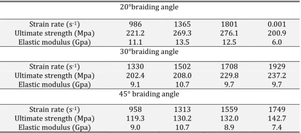
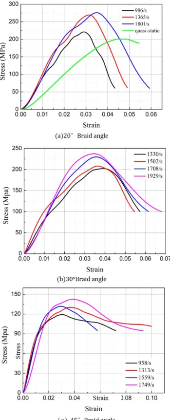
The results of transverse SHPB testing on braided angle composites at different angles are shown in Table 2, and the transverse compression stress-strain curves are shown in Figure 8. Figure 9 shows the failure morpholo-gy of the testing specimen under compression at different strain rates. Figure 10 presents the loading and failure process of the 20° braided angle composites at the strain rate of 1365/s photographed by a high-speed camera.
Table 2: Dynamic transverse compression properties of composites with different braiding angle.
20°braiding angle
Strain rate (s-1) 986 1365 1801 0.001
Ultimate strength (Mpa) 221.2 269.3 276.1 200.9
Elastic modulus (Gpa) 11.1 13.5 12.5 6.0
30°braiding angle
Strain rate (s-1) 1330 1502 1708 1929
Ultimate strength (Mpa) 202.4 208.0 229.8 237.2
Elastic modulus (Gpa) 9.1 10.7 9.7 9.7
45° braiding angle
Strain rate (s-1) 958 1313 1559 1749
Ultimate strength (Mpa) 119.3 130.2 132.0 142.7
Elastic modulus (Gpa) 9.0 10.7 8.9 7.4
It can be seen from Table 2 that the ultimate strength and elastic modulus of the 20° braided composites un-der the transverse compression both increase at the high-strain rate compared with the quasi-static state, indicat-ing that the material shows strengthenindicat-ing effect on the strain rate under the transverse compression. However, the higher the strain rate, the less obvious the change of mechanical properties. The ultimate strength and elastic modulus of the material at the strain rate of 1365/s were almost the same with those at the strain rate of 1801/s. At the high strain rate, the failure strain of the material increased with the increase of the strain rate, but it was much smaller than that of the material under the quasi-static condition. The mechanical properties of composites with 45° braid angle were similar to those with 30° under the transversal compression. As the strain rate in-creased, the ultimate strength of the material increased slightly and the elastic modulus did not show obvious change.
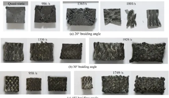
As seen from the morphologies of the testing specimens at different strain rates (Figure 9(a)), the higher the strain rate, the more serious the damage of the testing specimens: In the quasi-static state, there were two sym-metrical cracks in the plane perpendicular to the longitudinal direction. At strain rate 986/s, the crack deepened and spread wider, together with the separation of the matrix and fiber at the cracking. At strain rate 1365/s, the failure expanded from the partial crack to the whole testing specimen, with the fiber bundles breakage and shed-ding on the surface of the testing specimens. The length of the testing specimens in the through-thickness direc-tion increased obviously when it was squeezed. At strain rate 1801/s, the testing specimens broke into several pieces, and the fiber bundles were fractured at the surfaces of the ruptured pieces. It can be seen from the mor-phologies of 20° braided composites under compression that the failure modes of the tested composites at the quasi-static and high strain rates were similar; both of them produced two cracks along the middle point of one side to the two opposite ends of the opposite side. The higher the strain rate, the more extensive the crack ex-panded, and the more serious the damage was caused o the tested composites.
Figure 9: Failure modes of composites with different braid angles under transversal compression
The pictures from the high-speed camera (Figure 10) show that the material had much better ductility under the transverse compression than under the longitudinal compression. During the spreading process of the first stress wave, due to the flying out of some of the fiber bundles and matrix in the testing specimen during the com-pression process, the compressed testing specimen became porous, and at last part of the deformation was recov-ered. Under the transverse compression, the failure modes of the composites mainly include fiber slip, matrix collapse and shear failure at the fiber-matrix interfaces.
Figure 10: High-speed photos of 20° braided composites under transversal dynamic compression (strain rate 1365/s)
3.2 Transverse compression behavior
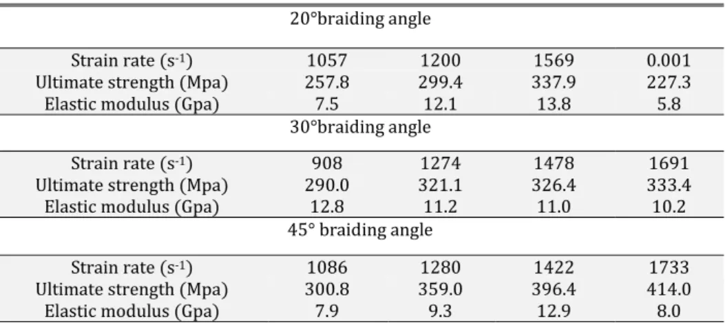
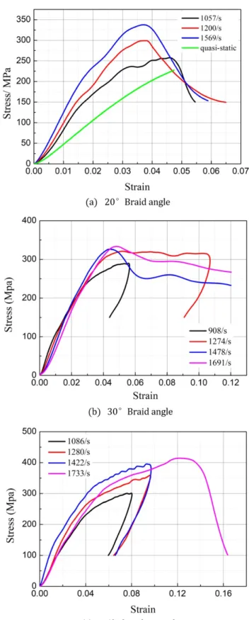
The compressive properties of composites with different braid angles in the through-thickness direction are shown in Table 3. The stress-strain curves of different braid angles in the through-thickness direction are shown in Figure 11. The failure morphologies of the testing specimens under different strain rates are shown in Figure 12. Figure 13 presents photos of the dynamic compression process of the 20° braided angle composites in the thickness direction at the dynamic strain rate of 1365/s taken by the high-speed camera.
20°braiding angle
Strain rate (s-1) 1057 1200 1569 0.001
Ultimate strength (Mpa) 257.8 299.4 337.9 227.3
Elastic modulus (Gpa) 7.5 12.1 13.8 5.8
30°braiding angle
Strain rate (s-1) 908 1274 1478 1691
Ultimate strength (Mpa) 290.0 321.1 326.4 333.4
Elastic modulus (Gpa) 12.8 11.2 11.0 10.2
45° braiding angle
Strain rate (s-1) 1086 1280 1422 1733
Ultimate strength (Mpa) 300.8 359.0 396.4 414.0
Elastic modulus (Gpa) 7.9 9.3 12.9 8.0
As shown in figure 11(a), the 20° braided angle composites, the ultimate strength and elastic modulus of the tested materials all increased to some extent with the increase of strain rate, indicating that the composites also present enhancement effect on the strain rate when compressed in the thickness direction. In the quasi-static tests, the stress-strain curves featured with a significant inflection point when the strain reached 0.05, and then the stress and strain kept rising, the curves did not decline even when the strain rose up to 0.35. This is because under the quasi-static compression, testing specimens were given enough time to adapt to strain changes and the internal fiber bundle could be compressed more tightly, so that even if the force became very large, it is still diffi-cult to crush it. Hence, the inflection point was selected, where the testing specimens turned from the elastic stage into a plastic stage, as the ultimate strength under the quasi-static compression. As it can be seen from the com-parative curves, the ultimate strength and elastic modulus under the static compression were both less than the corresponding parameters of high strain rate. The morphologies of the 20° testing specimens (figure 12(a)) un-der different strain rates shows that the higher the strain rate, the more serious the damage of the testing speci-mens: At 1057/s, the testing specimen cracked along the diagonal direction of the surface under the shear force; At 1200/s, the testing specimen shear failure occurred, as the internal fiber bundles broke during their interac-tion process; At 1569/s, the testing specimen shear failure was more serious, and was broken into three smaller pieces.
Figure 13 taken by the high speed camera shows the spreading process of the first stress wave. It is found that the testing 20° braided composite specimen was crushed into three pieces and eventually both flew outwards. The material damages at the quasi-static and high strain rate are also different: the former failure mode is the cracking and deformation of the matrix, with the fiber bundle being partially distorted. With noticeable extruded resin on the surface, and the material was crushed flat but remained intact; The latter involves shear fracture and matrix shear yielding of fiber bundles.
When the testing specimen with 30° braid angle was compressed in the thickness direction (figure 11(b)), the ultimate strength increased slightly and the elastic modulus decreased slightly with the increase of strain rate. When the strain rate was higher than 1200/s, the change in the two parameters was not obvious. At the two strain rates of 908/s and 1274/s, the stress-strain curves behaved in a similar way to the hysteresis curve, show-ing that the material deformed under pressure, but it was not destroyed, followed by the rebound of the incident bar, helping recovery of most of the deformation, which is similar to the loading-unloading process of metals. It can also be seen from Figure 12 (b) that there is almost no deformation in the material at these two strain rates. At 908/s, the testing specimen hardly presented any change in the morphology. At 1274/s, the edge of the testing specimen was slightly damaged and its surface had diagonal cracks, with noticeably extruded resin. At 1478/s, the testing specimen encountered shear failure and was split diagonally. However, there were still fiber bundles con-nected inside rather than being completely separated. At 1691/s, the testing specimen fractured diagonally into two pieces, with noticeable broken fiber bundles and resin powder.
Figure 12: Compression failure modes of composites with different braid angles in thickness direction
Figure 13: High-speed photos of 20° braided composites under compression in thickness direction (strain rate 1569/s)
4 Influence of braiding angle
Figure 14: Compressive behavior of braided composites with different braiding angle in the longitudinal direction
Figure 15 shows the comparison stress-strain curves of composites under with different braiding angle in the transverse direction. It can be seen that the ultimate strength and elastic modulus of the material decreased to a certain degree as the braid angle increased. The ultimate strength and elastic modulus of braiding angle of 20°, 30° and 45° were respectively 269.3MPa, 202.4MPa, 130.2Mpa, 13.3GPa, 9.1GPa and 10.7GPa. Compared with the values in the 20° braiding angle, the ultimate strength and elastic modulus of 30° braiding angle composites de-creased by 24.8%, 31.6% and for 45°, respectively by 51.7% and 19.5%. Compared with the case of the longitudi-nal compression, the braiding angle has a relatively small influence on the mechanical properties under trans-verse compression. The braided composites was mainly subjected to shear failure under transtrans-verse compression. This is because the fiber bundles in the shear plane is more easily to be torn and the the fiber bundles out of the shear plane are more prone to fracture by the shearing force as the braiding angle increases. Accordingly, the mechanical properties in the transverse direction decrease.
Figure 15: Compressive behavior of 3D braided composites with different braiding angle in the transverse direction
testing specimen of 20° braid angle broke into two parts, while the testing specimens of 30° and 45° braid angles were basically not damaged. The results show that the larger the braid angle, the better the mechanical properties in the direction of thickness. This is because the small unit cell size allows fiber bundles arranged closer in the thickness direction for the composites with larger braiding angle, resulting in better impact resistance.
Figure 16: Compression stress-strain curves of composites with different braid angles in thickness direction
5 CONCLUSIONS
In the current study, the quasi-static and dynamic compression tests were conducted in different directions on the three-dimensional four-step braided composites with different braiding angles. The main conclusions are as follows:
(1) For 3D braided composites, the compressive ultimate strength increases with the strain rate in the longitudinal, transverse and thickness directions, showing obvious strain rate strengthening effects in all directions. The composites with 20° and 45° braid angles are most sensitive to strain rates in the longitudinal direction, followed by the thickness direction, and least sensitive in the transverse direction. The composites with the 30° braid angle are also most sensitive to strain rates in the longitudinal compression, while it is less sensitive in the transverse and through-thickness directions. At high strain rates, the composites present the failure mode of brittleness than under the quasi-static compression, particularly in the longitudinal direction.
(2) The braid angle affects the mechanical properties of the composites under the dynamic compression in all three directions. The larger the braid angle, the weaker the mechanical properties in the longitudinal and transverse directions, the stronger the mechanical properties in the through-thickness direction. The braid angle has the greatest impact on the longitudinal mechanical properties. In particular, stress-strain curves were similar to the hysteresis curve for both the 30° and 45° braided angle specimens under pressure in the thickness direction. The composites were deformed under pressure but not destroyed. Then the incident bar rebounded, so that most of the deformation of the material was restored, similar to the loading-unloading process of metals. Subsequently, as the strain rate kept increasing until the testing specimen was damaged, and the stress-strain curve changed to a bell shape again. (3) The three-dimensional four-step braided composites have different failure modes when compressed in different directions, as well as in
different strain rate. The failure modes during longitudinal quasi-static compression mainly involves interface debonding and matrix cracking, while the fiber bundles and matrix were separated at the high strain rate longitudinal compression. The transverse compression mainly caused damages including fiber slip, matrix crushing, as well as shear failure of the fiber bundle and the matrix interfaces. The quasi-static compression in the thickness direction lead to cracking and deformation of the matrix, partial distortion and damage of the fiber bundles, whereas in the high strain rate compression, the fiber bundle shear fracture and matrix shear yield occurred.
Funding
References
Bilisik, K. (2013). Three-dimensional braiding for composites: A review. Textile Research Journal 83(13): 1414-1436.
Fan, W., Li, J. L., Wang, H., et al. (2015). Influence of thermo-oxidative aging on the impact property of convention-al and graphene-based carbon fabric composites. Journconvention-al of Reinforced Plastics and Composites 34(2): 116-130.
Fang, G., Liang, J., Wang, Y., et al. (2009). The effect of yarn distortion on the mechanical properties of 3D four-directional braided composites. Composites Part A: Applied Science and Manufacturing 40: 343-35.
Fang, G., Liang, J., Lu, Q., et al. (2011). Investigation on the compressive properties of the three dimensional four-directional braided composites. Composite Structures 93(2): 392-405.
Flanagan, M.P., et al. (1999). An Experimental Investigation of High Velocity Impact and Penetration Failure Modes in Textile Composites. Journal of Composite Materials 33(12): 1080-1103.
Gan, X., Yan, J., Gu, B., et al. (2012) Impact tensile behavior and frequency response of 3D braided composites. Textile Research Journal 82(3): 280-287.
Ge, J., He, C., Liang, J., et al. (2018). A coupled elastic-plastic damage model for the mechanical behavior of three-dimensional (3D) braided composites. Composites Science and Technology 157: 86-98.
Gong, J.C., Sankar B.V. (1991). Impact Properties of Three-Dimensional Braided Graphite/Epoxy Composites. journal of composite Materials 25: 715-731.
Gu, B., Chang, F. (2007). Energy absorption features of 3-D braided rectangular composite under different strain rates compressive loading. Aerospace Science and Technology 11(7-8): 535-545.
Huang, Z. (2016). Efficient Approach to the Structure-Property Relationship of Woven and Braided Fabric-reinforced Composites up to Failure. Journal of Reinforced Plastics and Composites 24(12): 1289-1309.
Jenq, S.T., Mo, J.J. (1996). Ballistic Impact Response for Two-Step Braided Three-Dimensional Textile Composites. AIAA journal 34(2): 375-384.
Jenq, S.T. Kuo, J.T., Sheu, L.T. (1998). Ballistic Impact Response of 3-D Four-Step Braided Glass/Epoxy Composites. Key engineering materials 141-143: 305-336.
Kamiya, R., Cheeseman, B.A., Popper, P, et al. (2000). Some recent advances in the fabrication and design of three-dimensional textile preforms: a review. Composite science and technology 60(1): 33 - 47.
Li, D., Lu, Z., Fang, D. (2009). Longitudinal compressive behavior and failure mechanism of three-dimensional five-directional carbon/phenolic braided composites at high strain rates. Materials Science and Engineering: A 526(1-2): 134-139.
Li, D., L. Chen, Li J. (2010). Microstructure and unit-cell geometry of four-step three-dimensional rectangular braided composites. Journal of reinforced plastics and composites 29(22): 3353 - 3363.
Li, D., Lu, Z., Jiang, N., et al. (2011). High strain rate behavior and failure mechanism of three-dimensional five-directional carbon/phenolic braided composites under transverse compression. Composites Part B: Engineering 42(2): 309-317.
Li, Y., Sun, B., Gu, B. (2017). Impact shear damage characterizations of 3D braided composite with X-ray micro-computed tomography and numerical methodologies. Composite Structures 176: 43-54.
Li, Y., et al., (2016). Dynamic responses and damage evolutions of four-step three-dimensional braided compo-sites subjected to high strain rate punch shear loading. Journal of Composite Materials 50(12): 1635-1650.
Mouritz, A.P., Bannister, M.K., Falzon, P.J., et al. (1999). Review of applications for advanced three-dimensional fibre textile composites. Composites. Part A: Applied science and manufacturing 30(12): 1445 - 1461.
Pan, Z., Gu, B., Sun, B. (2015). Experimental investigation of high-strain rate properties of 3-D braided composite material in cryogenic field. Composites Part B: Engineering 77: 379-390.
Sun, B., Liu, F., Gu, B. (2005). Influence of the strain rate on the uniaxial tensile behavior of 4-step 3D braided composites. Composites Part A: Applied Science and Manufacturing36(11): 1477-1485.
Sun, B., Gu, B. (2007a). High strain rate behavior of 4-step 3D braided composites under compressive failure. Journal of Materials Science 42(7): 2463-2470.
Sun, B., Gu, B. (2007b). In-plane Compressive Behaviors of 3-D Textile Composites at Various Strain Rates. Ap-plied Composite Materials 14(3): 193-207.
Song, Z., Wang, Z., Ma, H., et al. (2014). Mechanical behavior and failure mode of woven carbon/epoxy laminate composites under dynamic compressive loading. Composites: Part B 60: 531-536.
Tang, G., Yan, Y., Chen, X., et al. (2001). Dynamic damage and fracture mechanism of three-dimensional braided carbon fiber/epoxy resin composites. Materials and Design 22(1): 21 - 25.
Wan, Y., Wang, Y., Gu, B., (2015). Finite element prediction of the impact compressive properties of three-dimensional braided composites using multi-scale model. Composite Structures 128: 381-394.
Wang, B.L., et al. (2010). Experimental Investigation on Compressive Properties for 3D Four-Directional Braided Composites. Advanced Materials Research 160-162: 1744-1748.
Wang, B., Fang, G., Liu, S., et al. (2018). Progressive damage analysis of 3D braided composites using FFT-based method. Composite Structures 192: 255-263.
Xu, J., Gu, B. (2002). Damage pattern and failure mode of 3-D braided composites under ballistic impact, Journal of Ballistics14(2): 39-43 (In chinese)
Zhang, C., Curiel-Sosa, J.L., Duodu, E.A. (2017). Finite element analysis of the damage mechanism of 3D braided composites under high-velocity impact. Journal of Materials Science 52(8): 4658-4674.
Zhang, D., et al. (2015). Meso-scale finite element analyses of three-dimensional five-directional braided compo-sites subjected to uniaxial and biaxial loading. Journal of Reinforced Plastics and Compocompo-sites 34(24): 1989-2005.
Zhang, F., et al. (2014a). Impact compressive behavior and failure modes of four-step three-dimensional braided composites-based meso-structure model. International Journal of Damage Mechanics 24(6): 805-827.
Zhang, W., et al. (2014b). Effects of temperature and strain rate on impact compression behaviors of three-dimensional carbon fiber/epoxy braided composites. Journal of Composite Materials 49(7): 771-782.
Zheng, X., et al. (2011). Numerical Simulation on Damage and Failure in 3-Dimensional Braided Composites Struc-ture against Bird Strike. Polymer & Polymer composites 19(2&3): 243-246.
Zhou, H., et al. (2016). Experimental and numerical investigation of the transverse impact damage and defor-mation of 3-D circular braided composite tubes from meso-structure approach. Composites Part B: Engineering 86: 243-253.