BJRS
RADIATION SCIENCES
07-02A (2019) 01-12ISSN: 2319-0612
Accept Submission: 2018-12-21
Development of an automated system for the operation
of an electron beam accelerator
S. L. Somessari; J. A. Moura; W. A. P. Calvo
Instituto de Pesquisas Energéticas e Nucleares (IPEN -CNEN / SP) Av. Professor Lineu Prestes 2242 - 05508-000 - São Paulo, SP – Brazil
ABSTRACT
Electron beam accelerators are used in many applications, such as basic physical research, chemistry, medicine, molecular biology, microelectronics, agriculture and industry, among others. The majority of the accelerators have electrons from a hot tungsten filament and their energy is increased as it passes through an electric field in the vacuum chamber. For industrial purposes, the most common model is Dynamitron®. At IPEN-CNEN/SP, there is an electron beam accelerator Dynamitron® Type (Manufactured by RDI - Radiation Dynamics Inc., 1978) model DC1500/25/4. The technology applied was available in the 60´s and 70´s, but, nowadays is obsolete. Moreover, there are not original spare parts for this equipment any longer. The aim of this work is to develop a nationalized automated operation system for the accelerator, to replace the old equipment and allow extending the useful life of the accelerator for around ten years.
Somessari S. L., et. Al. ● Braz. J. Rad. Sci. ● 2019 2
1. INTRODUCTION
Particle accelerators are sophisticated and expensive equipment used to accelerate electrically charged particles such as electrons, protons and ions, besides less common particles, like positrons. The equipment and process are the result of years of research and dedication of dozens of thousands of professionals, in many countries. Its various applications range from industry, medicine, basic physical research, molecular biology, chemistry and agriculture, among others. At the end of the 1920´s, it became clear that natural radioactive sources were not enough anymore and the ion accel-erators were necessary in the development and research of nuclear physics. At the beginning of the 1930´s, different types of accelerators started to be developed, almost simultaneously: the linear high frequency accelerator, the Circular and the Direct Current accelerator. Cockroft and Walton built their first generator of 600 keV, cascade type, in 1932. Almost at the same time, Robert Van de Graff built his 1.5 MeV machine.
All the electron beam accelerators have an electron source, a vacuum acceleration chamber and a device to extract and distribute the electrons over the product surface. The majority of the accelera-tors have electrons from a hot tungsten filament and their energy is increased as it passes through an electric field in the vacuum chamber. For industrial purposes, the most common model in the mar-ket is Dynamitron® [1,2]. At IPEN-CNEN/SP, there is an electron beam accelerator Dynamitron® Type (Manufactured by RDI- Radiation Dynamics Inc., 1978, model DC1500/25/4 [3,4]. This ac-celerator is used to reticulate the insulation of electric cables and wires, polyethylene blankets and retractable tubes, besides medical products radio sterilization, composites and polymeric materials modification and food treatment [5-8]. The technology applied to this accelerator was available in the 60´s and 70´s, but, nowadays is obsolete. Moreover, there are not original spare parts for this equipment any longer.
The aim of this work is to develop a nationalized automated operation system for the accelerator, to replace the old equipment and allow extending the useful life of the equipment for around ten years. The project started with an economic and technical feasibility study and industrial dosimetry study. The safety standards from the IAEA and CNEN were used to guide the project. Several studies have been conducted and major development has been reached, including printed circuit boards
construc-tion, mechanical solutions, PLC (Programmable Logic Controller) automaconstruc-tion, software for the au-tomation and process parameters. In this work, the services of the Laboratory of Irradiation Process Dosimetry in the Radiation Technology Center in IPEN-CNEN-SP were used. The main results are the development of an automated control system, signal converting boards, electron beam intensity and sweep system, safety system, overall control system and a device to simulate the electrical sig-nals of the accelerator, allowing the whole system to be tested. This work will permit a considerable amount of money to be saved, once the complete new system from the manufacturer could reach as much as US$400,000.00.
2. MATERIALS AND METHODS
The facilities used were the Laboratory of High Intensity Radiation Sources and the Laboratory of Irradiation Process Dosimetry in the Radiation Technology Center at IPEN-CNEN/SP. The control panels of the Dynamitron® DC1500/25/4 Cockroft-Walton type accelerator, with energy of 1.5 MeV are shown in FIG.1 (command panels) and FIG. 2 (electrical protection and safety).
FIG.1: Command panels FIG.2: Electrical protection and safety The control panel of the electron beam, emergency stop, video cameras and the accelerator power control are shown in FIG.3 (electron beam control) and FIG.4 (power control).
Somessari S. L., et. Al. ● Braz. J. Rad. Sci. ● 2019 4
FIG.3: Electron beam control panel. FIG.4: Power control.
The panel of electron beam sweep is shown in FIG.5 and the indicators of the electron beam electrical parameters are shown in FIG.6.
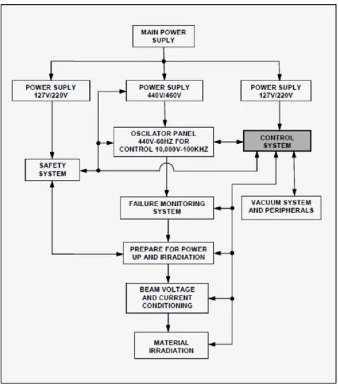
To perform the automated control was used a Programmable Logic Controller (PLC) Siemens model Simatic S7-1200 CPU with interface blocks for input and output digital and analogic signals. In FIG. 7 is shown the power management and highlighted block is the updated control system, with its interfaces. This block takes several signals as safety, failure, electron beam voltage and current, vacuum system status and others, and has control and management action over this parameters.
FIG.7: Flowsheet of power management.
FIG. 8 shows detailed process flowchart with the control system block and its interfaces. The main interfaces are vacuum system, safety system, power management, accelerator voltage control, oscil-lator, beam control and filament feeding.
Somessari S. L., et. Al. ● Braz. J. Rad. Sci. ● 2019 6
FIG. 8 shows a detailed flowsheet of process control.
A man-machine interface (MMI) allows the interaction of operator and the parameters setup in the control system block. An example of such MMI screen is shown in FIG. 9, where it can be adjusted beam sweep, beam energy and beam current.
During the electrical tests of the system was necessary to simulate current feedback signals to ensure proper control strategy. For this purpose was created one circuit to generate current feedback signals in the same range as the actual. FIG. 10 shows simulator connected to PLC interface during the electrical tests.
FIG. 10. Simulation of feedback signals
3. RESULTS AND DISCUSSION
With this scientific work an operating software and men machine interface were designed, allowing work in automated conditions and extend the estimated useful life of the accelerator for more than ten years. This development includes a PLC (Programmable Logic Controller) design and the correlate software. The design was, previously, based on the flowsheets of power management, shown in FIG.7, and process control, shown in FIG.8. The resulting electrical diagram of the Dynamitron® DC1500/25/4, used to develop the electrical devices and the automation software is shown in FIG.11.
Somessari S. L., et. Al. ● Braz. J. Rad. Sci. ● 2019 8
FIG.11: Electrical block diagram of the EBA.
Electron beam energy is proportional to the high voltage applied to the acceleration tube. This Voltage increases with the electrical supply of the oscillator, and this supply is controlled by the SCR bridge, whose gates are fired by the SCR firing system. PLC output interfaces with firing system and take command over the final high voltage. Several feedback electrical signals are send to PLC, corresponding to the controlled parameters. High voltage in the accelerator tube, electron beam current, beam sweep amplitude and filament current. Feedback signals are represented in the FIG. 12.
FIG.12: Signal feedbacks of the controlled parameters in the EBA. The design of the new automated system for the accelerator consists of:
a) Hardware - Microcomputer; Programmable Logic Controller (PLC); drivers for communica-tion; step motors; sensors; communication interfaces; electronic and pneumatic devices. An electronic interface board was constructed to take analogic feedback signals and feed it to the automated system. The board is shown in FIG.13.
FIG.13: Analogic signals electronic feedback board.
b) Software – Operational control software; vacuum, electron beam sweep drivers; PLC pro-gramming using Step S7-1200, from Siemens; man-machine interface propro-gramming (Web Stu-dio 8.0, from Indusoft). The various functions were integrated in the supervisor system running
in the man-machine interface software. The beam electron sweep control is shown in FIG. 14.
Somessari S. L., et. Al. ● Braz. J. Rad. Sci. ● 2019 10
The new automated system used the original electromechanical devices like pumps, control coils, heating and cooling units and transformers, among others, and improved its integration and effi-ciency. The quality of acquired data and the resulting control action where also improved. Useful life expectance was extended, saving money in the upgrade budget. The entire project execution cost USD 62,000.00, compared to the manufacturer's delivery cost of USD 400,000.00.
The resulting spectrum of the electron beam was measured and comply with standard expected results. This spectrum is shown in FIG. 15. As expected, the scan width is measured to be about 1.02m long. Irradiation uniformity across the tray (700 mm) of the conveyor is evaluated to be -10% to +30% from the average delivered dose. Those results show that the products to be irradiated must be placed in the center of the tray where the surface dose is the most homogeneous. For prod-ucts larger than 350 mm, one can expect a surface dose variation higher than +/- 5%. This main capabilities remained unaltered after the accelerator upgrade, allowing perform the same tasks done before, with more reliable operational resources due to the automation applied.
4. CONCLUSION
The inclusion of several modern analog and digital electronic devices with software development and the integration of electromechanical parts and power units implemented in this project bring a new life cycle to this equipment. Otherwise the absence of original spare parts and its own obsoles-cence and the cost of the upgrade by the manufacturer would result in a not feasible project. Once the operational aspects where attended, the reduced cost reached with local development and buying and adapting alternative parts allowed to extend the productive use of the installation, with more precise control and more trustworthy operational functions. The main goal reached in this project was increasing useful life of the accelerator, extended at least for more ten years. Besides that the inversion needed with this upgrade was much smaller than the manufacturer cost.
REFERENCES
1. E. COTTEREAU, Tandetron, DC accelerator – CNRS/CEA, Bat 30 Ave de la Terrasse, F-91198 Gif sur Yvette Cedex, France. Disponível em : https://cas.web.cern.ch/cas/Pruhonice/PDF/DC-accel-DB1.pdf> Acesso em: 22 julho 2014.
2. RADIATION DYNAMICS, INC – RDI. General Dynamitron manual of electron beam accelera-tor.
3. CALVO, W. A. P. et al. Electron beam accelerators - trends in radiation processing Technology for industrial and environmental applications in Latin America and the Caribbean. Radiation Phys-ics and Chemistry, v.81 (2012), p.1276–1281.
4. DUARTE, C. L. et al. Electron beam combined with hydrothermal treatment for enhancing the enzymatic convertibility of sugarcane bagasse. Radiation Physics and Chemistry, v.81 (2012), p.1008–1011.
Somessari S. L., et. Al. ● Braz. J. Rad. Sci. ● 2019 12
5. SOMESSARI, S. L. ; SILVEIRA, C. G.; PAES H.; SOMESSARI, E. S. R. – Electron beam ac-celerator facilities at IPEN-CNEN/SP. In: International Nuclear Atlantic Conference (INAC 2007). Proceeding… Santos, SP, Brazil, September 30 to October 5, 2007.
6. INTERNATIONAL ATOMIC ENERGY AGENCY (IAEA). Radiation Processing: Environmen-tal Applications –ISBN 92-0-100507-5 – IAEA – Library CaEnvironmen-taloguing Publication Data - Vienna – 2007.
7. INTERNATIONAL ATOMIC ENERGY AGENCY (IAEA). Radiation treatment of gaseous and liquid effluents for contaminant removal – Proceeding… of technical meeting held in Sophia – Bul-garia – 07-10 Sept, 2004.
8. INTERNATIONAL ATOMIC ENERGY AGENCY (IAEA). Radiation Technology series 1 – Use of mathematical Modelling in Electron Beam Processing: A Guidebook - Vienna – 2010