Registration Code: S-I1465901644
A FIBRE-BASED FRAME ELEMENT WITH EXPLICIT
CONSIDERATION OF BOND-SLIP EFFECTS
R. Sousa (1), A. A. Correia (2), J. P. Almeida (3), R. Pinho (4) (1)
Ph.D. Student, ROSE Programme, UME School, IUSS Pavia, Pavia, [email protected] (2)
Postdoctoral Researcher, National Laboratory for Civil Engineering, Lisbon, [email protected] (3)
Postdoctoral Researcher, École Polytechnique Fédérale de Lausanne, Lausanne, [email protected] (4)
Assist. Prof., Dept. of Civil Engineering and Architecture, University of Pavia, Pavia, [email protected]
Abstract
Reinforced concrete (RC) frames subjected to seismic loading often depict localized member-end deformations due to strain penetration effects between adjacent members, such as beam-column and column-footing joints. Past experimental programs indicate that the bond-slip deformations occurring at the interface between the reinforcement and the surrounding concrete can contribute up to 40% of the lateral deformation of the RC members.
The employment of advanced bond-slip models within detailed finite element formulations, capable of simulating continuous domains with highly discretized meshes, has witnessed great advances over the recent years with encouraging results. Nonetheless, this modelling approach is computationally heavy and hence inapplicable for practical seismic (nonlinear) analysis of structures. Alternatively, the use of beam-column elements with lumped or distributed plasticity is a more computationally efficient and engineering-friendly modelling approach. Unfortunately, the elements of this type available in conventional numerical packages did not yet consider an explicit simulation of the interface between the reinforcing bars and the surrounding concrete along their embedment length.
The present study aimed at overcoming the foregoing limitation by developing an explicit bond-slip model applicable to general fibre-based beam-column elements. Using a state-of-the-art bond-slip constitutive model, the current paper introduces a zero-length element that computes the localized member-end deformations accounting for the bond-slip response at each reinforcing bar of a given RC section. Along with the material properties and anchorage conditions, the proposed nonlinear model also accounts for cyclic degradation and rebar yielding effects. Validation studies conducted with the proposed numerical formulation reveal a good agreement with past experimental tests, evidencing an important stability and accuracy at the expense of an acceptable additional computational effort.
1. Introduction
Since the incorporation of steel reinforcement in concrete, back in the mid-19th century, the bond conditions between steel and concrete have been the subject of numerous studies. One of the major application breakthroughs occurred in the early years of the 20th century with the introduction of deformed surface rebars in substitution of conventional plain rebars. This innovation improved the adhesion between the two materials and, consequently, reduced the embedment length (Le) required to anchor the axial load developed at a given rebar.
When subjected to bending, and despite the substantial improvement of the bond resistance provided by deformed rebars, whenever the embedment length is insufficient, the rebar experiences an important increase of slip, leading to a large growth of the element’s base rotation or even failure of the anchorage system (Fig. 1).
Fig. 1 – Anchorage region with adequate (left) and limited (right) embedment length (adapted from [1]) From a structural engineering viewpoint, strain penetration (SP) effects are particularly relevant as they can result in significant member-end displacements and rotations if a given RC member is subjected to large seismic loads. Despite the previous considerations, in most engineering applications it is common practice to consider that the reinforcing bars are perfectly bonded to the surrounding concrete, i.e., the relative slip deformations, occurring essentially at the connection to foundations systems and at beam-column joints, are neglected. This option reflects an erroneous perception that most of the deformations in RC members are essentially dictated by the deformation occurring along the members’ clear span. Nonetheless, experimental campaigns conducted on RC columns [2] and on beam-column joints [3, 4] have shown that the contribution of strain penetration mechanisms can contribute up to 40% of the overall lateral deformation. This is in line with the results presented in Fig. 2, obtained by Goodnight et al. [5], in which circular RC bridge columns are considered. The different colours represent the contributions of the different mechanisms to the total lateral deformation of the columns for increasing levels of ductility: in red, the component associated with the flexural deformation at the plastic hinge regions; in blue, the one associated with the SP effects; and, in green, the remaining sources of flexibility.
In this context, particular attention to this phenomenon should be paid in the assessment of RC structures built during the first half of the 20th century, given that most of these structures were built with plain rebars. In such cases, the consideration of SP effects becomes even more critical – experimental tests conducted on both RC columns [6] and beam-column joints [7] reveal that this mechanism may contribute to nearly 90 % of the overall member deformation at failure.
The present paper explores some aspects related with the modelling of SP effects in seismic analysis of structures. The subsequent sections present a summary of alternative simulation tools, followed by a description and validation of a new bond-slip model proposed by the authors.
2. Current Bond-Slip Numerical Models
Despite the recognized importance of strain penetration effects on the response of RC structures, the consideration of such effects in numerical models is still limited to the use of very simplified models [8]. One of the main causes is the lack of suitable models in most conventional numerical software for structural analysis. In the following, some of the most relevant of the existing numerical models are presented, and their main features and limitations are pointed out.
The use of advanced bond-slip models within detailed finite element models, capable of simulating continuous domains with highly discretized meshes, has witnessed great advances over recent years, evidencing encouraging results (e.g., [9, 10, 11, 12]). This type of models allow the adoption of either a perfect adhesion between the reinforcement and surrounding concrete or the assignment of different bond-slip constitutive laws for the relation between the bond stress and the slip occurring at the concrete/rebar interface. However, despite the promising results achieved with these models, this type of modelling approach is computationally very demanding, rendering the seismic nonlinear analysis unfeasible for most practical applications.
Alternatively, the use of beam-column elements, featuring lumped or distributed plasticity, represents a more efficient option, producing accurate results for conventional RC framed structures. However, for this latter case it is difficult to explicitly describe the interface between the reinforcement and the surrounding concrete along the embedment length of the rebar. Therefore, the problem has been traditionally tackled by simplified formulations based on (essentially) empirical relations.
One of the simplest approaches involves the consideration of a constant bond stress value along the development length of the reinforcing bar (e.g., [13]). In such cases, for a given imposed force, it is possible to determine the development length required to satisfy the equilibrium at the anchorage region. Given that the rebar force (and consequently its axial stress and strain) distribution corresponds to the integral of the bond stresses and that the slip at the loaded-end can easily be determined as the integral of the relative steel/concrete strains, the computation of the slip at the loaded-end thus involves a double integration of the bond stresses. Despite being an extremely efficient procedure, this approach is based on the simple but erroneous assumption that the bond stress is constant along the embedment region. As noted in Section 3 and 4 below, the bond properties along the rebar may vary significantly depending on the anchorage properties and loading demand. As such, it becomes extremely difficult to establish a constant averaged bond stress a priori.
A completely different approach was proposed by Zhao and Sritharan [14]. This model, implemented in OpenSEES [15], considers a stress-slip hysteretic model that can be integrated into fibre-based analysis of concrete structures using a zero-length element. The hysteretic rule was derived based on a compilation of 16 experimental tests featuring a minimum pre-established anchorage length. An interesting feature of this approach is that it manages to directly translate the rebar stress into rebar slip, and not strain as it generally occurs in fibre-based models. However, considering that the adopted hysteretic relation is purely empirical, a significant calibration effort may be required for adjusting the different parameters in order to accommodate alternative anchorage conditions, namely the consideration of a reduced embedment length or the presence of plain rebars, as noted by Melo et al. [7].
Finally, Monti and Spacone[16] proposed a RC beam finite element that explicitly accounts for the slip between the reinforcing bars and the surrounding concrete, merging the bond-slip formulation into a force-based fibre element. The member-end cross-section retains the plane sections’ assumption, but the steel fibre strains
are computed as the sum of two contributions: the rebar deformation and the anchorage slip. The latter is modelled through a series of additional force-based (FB) elements representing the embedment length of the rebars. The definition of several elements with different integration points (IPs) along the embedment length is a very interesting strategy, bypassing the limitations of simpler models as the ones described before. Despite making use of a powerful framework, the employment of a FB formulation to model the bond-slip behaviour does not provide the exact equilibrium solution as obtained for traditional FB beam-column elements. The reason for this is because the assumed linear interpolation function of bond stress between adjacent IPs is not exact, and the actual bond distribution can only be achieved at the expense of considering a substantial number of elements. This observation is particularly relevant considering that the development length at each load step is not fixed, i.e., the active length of the elements depends on the history and amplitude of the loading demand. Moreover, as observed later in this paper, the distribution of bond stresses may vary significantly under cyclic loading or when considering the (localized) bond stress reduction in the yielded regions of the rebars.
3. Brief Description of the Proposed Bond-Slip Model
As described in the previous section, it is possible to explicitly describe SP effects through bond-slip models implemented in solid finite element software. However, in software using simpler beam-column elements, which are significantly more efficient for framed RC structures, the SP models currently available are still somewhat limited. Alternatively, and despite the improvements observed in the simulated responses, the employment of simplified approaches such as the use of linear springs at the members’ ends, elongated elements or a reduced elastic modulus for the reinforcement, exhibit important drawbacks as demonstrated by Sousa et al. [8].
As an attempt to overcome the foregoing limitations, a study was conducted in order to develop an intelligible bond-slip model that can be used with fibre-based beam-column elements. Based on the literature review (more details available in [17]), it became apparent that the model should be able to account for the following mechanical properties and physical phenomena:
• Type of bond-slip failure (pull-out or splitting)
• Concrete strength
• Embedment length
• Cyclic degradation
• Amplitude of steel strains (rebar yielding)
• Rebar properties (plain or ribbed rebars)
• Transverse pressure
• Level of confinement
Considering the properties and phenomena involved, it is clear that the simulation of the anchorage region of a given RC member cannot be based on simple pre-established empirical relations. However, most of these phenomena can be directly accounted for through appropriate bond-slip local constitutive relations, which describe the magnitude of bond stresses along the interface between the rebars and the surrounding concrete for a given history of slip values.
Hence, in order to satisfy the previous requirements, it seems natural to define a series of monitoring points along the rebar that keep track of all the response parameters. Naturally, this implies developing a consistent and robust formulation to guarantee that both equilibrium and compatibility are respected within the model development framework.
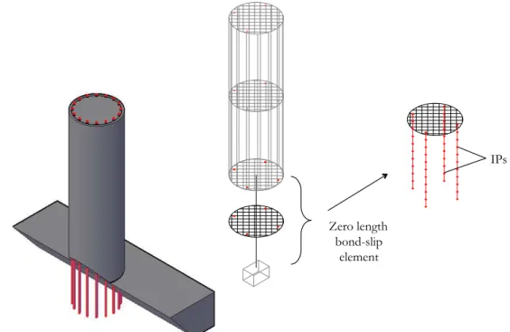
In addition to the previous guiding principles, it is important to guarantee the simplicity and efficiency of the model so that both researchers and practitioners can use it in their applications with an acceptable computational effort. As such, the proposed model was developed as a zero-length element, to be located at the extremity of structural members, which simulates the behaviour of the rebars’ anchorage zone adjacent to a RC frame member. The end-section of the frame element is thus replicated and a set of auxiliary IPs is defined along the
actual (yet, not explicitly modelled) embedment length of all rebars of the cross-section. A schematic representation of the model components is presented in Fig. 3, where for clarity the number of rebars represented in the numerical model was reduced with respect to the actual RC member on the left-hand side.
Fig. 3 – Schematic representation of the different components of the proposed bond-slip model
In the proposed formulation, the reinforcement is modelled through a simple bilinear relation whilst the bond stress-slip curve adopted is the one prescribed in the Model Code 2010 [18]. Regarding the cross-sectional fibres assigned with concrete material, the response is determined following the concrete model adopted for the adjacent member.
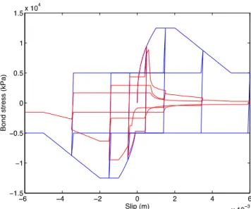
The choice of the constitutive relation proposed in the Model Code 2010 [18] allows taking into account several characteristics that may impact on the bond properties, namely the ones listed above. Whilst most of them are defined a priori, the ones associated with the cyclic degradation effects and the reduction of bond strength due to yielding of the rebars are updated during the analysis as a function of the history and amplitude of the applied loads. Fig. 4 represents, in a qualitative manner, the reduction of bond stresses due to cyclic degradation and rebar yielding (red line) with respect to the case where the effect of these phenomena are disregarded (blue line). The interested reader can find additional details on the definition of the constitutive relation in [17] and [18].
Zero length bond-slip
element
Fig. 4 – Qualitative comparison between the implemented bond stress-slip model without (blue) and with (red) the effects of yielding and cyclic degradation
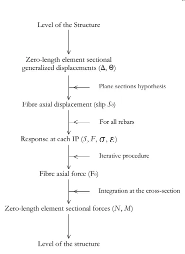
The proposed model adopts the basic framework generally adopted in finite element formulations and, therefore, one is interested in determining the nodal element forces associated to an increment of nodal element displacements. The following points synthetize the main steps considered in the proposed model in a very succinct manner due to space limitations.
1. For a given nodal displacement, the slip at every rebar of a cross-section is determined based on the plane sections’ hypothesis.
2. For a given slip imposed at the rebar (S0), the different response parameters (slip, bond stress, rebar force and strain) are determined for every IP based on the Forward Euler method.
3. The anchorage force (F0) at the loaded-end of each rebar is iterated following the bisection method until convergence is attained. At each iteration, F0 is determined through the integration of the bond stresses at every IP defined along the anchorage length. In this iterative procedure both equilibrium and compatibility are enforced at every point along the rebar where each IP features independent constitutive relations.
4. The force associated with the concrete fibres is determined as for a general section but, in this case, the strains are computed assuming that the fibre displacement corresponds to a constant strain along an influence length – Li (described in more detail hereafter).
5. The contribution of the different fibres of the cross-section is then summed up in order to compute the member-end forces (axial force and flexural moments in the two orthogonal directions).
6. The response at the sectional level associated with the bond-slip effects is finally incorporated into the structural level of the analysis.
The previous procedure is described in a simplified manner in the flowchart of Fig. 5. For additional details the reader is referred to [17].
Fig. 5 - Simplified flowchart of the proposed bond-slip model
In summary, the proposed model requires several input parameters that, in essence, can be divided into three groups: (i) geometric, (ii) material and (iii) bond properties. The first group comprises the dimensions of the cross-section under analysis, the embedment length of the anchored rebars and an influence length for the concrete fibres. The latter represents the fictitious length, to the interior of a beam-column joint or foundation block, along which it is assumed that an average strain develops in the concrete fibres – as reference values one can consider two times the height of a foundation block or one time the width of a joint when simulating the bond-slip behaviour at a column-foundation or a beam-column connection, respectively. The second group represents conventional material properties that, in general, should coincide with the ones considered for the adjacent RC element (beam or column). Finally, the last group reflects the properties defining the adopted bond stress-slip constitutive relation; in the proposed model, it follows the one prescribed by the Model Code 2010 [18]. Although the choice of the influence length may require some calibration, it is important to note that all other parameters considered in the proposed procedure are calibration-free, thus rendering straightforward the application of the bond-slip element.
4. Validation of the Proposed Model
After performing the required validation tests, the proposed bond-slip model was implemented in the software
SeismoStruct [19], enabling to study in greater detail the performance of the new element. In the following, the
numerical response is compared with experimental results considering: (i) a pull-out test of one rebar, and (ii) a cyclic test of a circular RC bridge column (Fig. 6 (a) and (b), respectively).
Zero-length element sectional generalized displacements ( , )
Fibre axial displacement (slip S0)
Plane sections hypothesis
Response at each IP (S, F, , ) For all rebars
Fibre axial force (F0)
Iterative procedure
Zero-length element sectional forces (N, M)
Integration at the cross-section
Level of the structure Level of the Structure
(a) (b)
Fig. 6 – General dimensions of the experimental models: a) SD50 [20] and b) Test 19 [5]
The characteristics of both experimental tests allow the evaluation of: (i) the different response parameters along the embedment length of a rebar [20]; (ii) a more global evaluation of the force-slip response of a rebar or the rotation due to strain penetration effects at the extremity of a RC member [5]. It should be noted that the values adopted for the bond stress-slip constitutive relation represent standard values recommended by the Model Code 2010 [18], with no further calibration.
The main properties of the specimen considered in the pull-out test [20] are presented in Table 1. The results presented in Fig. 7 show the ability of the numerical model to reproduce the response of both force- and deformation-related parameters along the embedment length of the rebar. Notably, the model is able to capture the yielding effect in both the steel rebar as well as the bond responses. This effect is reflected in the abrupt reduction of bond stresses near the loaded-end of the rebar. At the same location, this reduction in bond strength results in a large increase of both strain and slip values. On the other hand, the rebar stresses show only a minor variation, as expected, given that the rebar enters its hardening branch.
Table 1 – Geometric and material properties adopted for test SD50 [20]
Anchorage characteristics Bond-slip model parameters
db (m) 0.0195 α 0.4
Le (m) 0.97 S1 (m) 0.001
fc (MPa) 19.6 S2 (m) 0.002
fy (MPa) 610 S3 (m) 0.01
fu (MPa) 800 τmax (MPa) 2.5
Es (GPa) 190 τf (MPa) 0.4 τmax
Es,p (GPa) ≈ 4.1
Fig. 7 - Comparison between numerical and experimental results obtained for test SD50 [20]
The second example presents the experimental results from a circular RC column subjected to a cyclic imposed lateral displacement of increasing ductility demand, selected from an extensive study carried out by [5]. The geometry, load and material properties are presented in Fig. 6 (b) and Table 2.
Table 2 – Geometric and material properties adopted for Test 19 [5]
Anchorage characteristics Bond-slip model parameters
Axial force (kN) - λN 640.5 - 10% α 0.4
H (m) 2.44 S1 (m) 0.001
D (m) 0.457 S2 (m) 0.002
Long. reinf. (ρl) 10ϕ19 mm (1.7%) S3 (m) 0.01
Trans. reinf. (ρv) ϕ9.5 mm//0.05 m (1.3%) τmax (MPa) 2.5
db (m) 0.0189 τf (MPa) 0.4 τmax Le (m) 1.0 * Li (m) 0.46 / 0.92 ** fc (MPa) 43.7 fy (MPa) 470 fu (MPa) 637 Es (GPa) 188 Es,p (GPa) ≈1.4
λN -Axial load ratio
ρl , ρv –Longitudinal and transverse reinforcement ratio
* Approximate value based on available detailing information ** Parameter variation in the numerical analysis
The results presented in Fig. 8 show that the rotations attributed to the SP effects are simulated in a very satisfactory manner for the different ductility levels. The same figure allows also to assess the appropriateness of adopting different values of influence length (Li). The results seems to indicate that the consideration of Li as 2 times the height of the foundation (Li = 0.92 m) tend to match the experimental results in a satisfactory manner, despite such overestimation. In addition, Fig. 8 presents the results considering an elastic spring at the base of the column (green circles) as described in [8]. The results indicate that, after yielding (i.e., for ductility levels larger than one), the SP rotations remain essentially unchanged, which results in a significant deviation with respect to the experimental results (black circles), in particular for increasing levels of ductility.
Finally, Fig. 9 shows the evolution of the slip measurements at the most tensioned rebar of the cross-section with the lateral displacement imposed at the top of the column. The results indicate that the slip at that rebar is simulated with remarkable accuracy, especially considering the large number of cycles and the magnitude of the imposed load.
Fig. 8 - Comparison between experimental and numerical SP rotations of Test 19 [5] for different ductility levels
Fig. 9 - Experimental (left) and numerical (right) slip hysteresis at the most tensioned rebar of the base section of Test 19 [5] (1 in = 0.0254 m)
0 1 2 3 4 5 6 0 0.002 0.004 0.006 0.008 0.01 0.012 0.014 0.016 0.018 0.02 Ductility R o ta ti o n ( ra d ) Numerical (Li=0.92m) Numerical (Li=0.46m) Numerical (linear) Experimental
5. Conclusion
Different studies have shown the non-negligible contribution of strain penetration (SP) effects to the overall deformation of RC structures. Inspired by the difficulties in modelling these effects, this paper proposes a new numerical model for fibre-based beam-column elements capable of explicitly simulating the increased flexibility resulting from SP effects:
• Devised to work as a zero-length element, the model makes use of an advanced bond stress-slip constitutive relation, capable of describing the physical phenomena associated with SP effects for a wide variety of anchorage conditions depending on the concrete strength, embedment length, rebar surface characteristics, rebar yielding or cyclic degradation, among others. This represents an important advantage with respect to conventional empirical models, since the analyst can now make use of state-of-the-art constitutive models that accurately reproduce different anchorage conditions.
• The anchorage region replicates the cross-section of the adjacent RC member and preserves the plane sections’ hypothesis. Each of the cross-sectional rebars is represented through a number of integration points (IPs) distributed along its anchorage length. Using the Forward Euler method, the response at each IP is determined enforcing both equilibrium and compatibility requirements. Despite requiring small (spatial) step sizes, which leads to a large number of integration points, this option presents some advantages with respect to more conventional approaches, as the response along the embedment region of the rebar can be accurately determined, regardless of the boundary conditions and without the need to define an approximated interpolation function representative of the actual distribution of a given parameter (bond stress, rebar strains or slip).
• The bond-slip response at each rebar is iterated following the bisection method. The member-end nodal forces are then determined through the integral of the contribution of the cross-sectional fibres.
• The proposed bond-slip model was implemented in the well-known software SeismoStruct [19]. It proved able to simulate the strain penetration effects, both at the rebar and sectional levels. The accuracy of the model at different levels was confirmed through comparisons against experimental results, showing simultaneously an encouraging computational efficiency.
References
[1] Sritharan S, Priestley N, Seible F (2000): Nonlinear finite element analyses of concrete bridge joint systems subjected to seismic actions. Finite Elements in Analysis and Design, 36(3-4), 215–233.
[2] Sezen H, Moehle J (2004): Strength and Deformation Capacity of Reinforced Concrete Columns with Limited Ductility. 13th World Conference on Earthquake Engineering, Vancouver, Canada.
[3] Filippou F, Popov E, Bertero V (1983): Effects of Bond Deterioration on Hysteretic Behaviour of Reinforced Concrete Joints. Earthquake Engineering Research Center.
[4] Popov E (1984): Bond and Anchorage of Reinforcing Bars Under Cyclic Loading. ACI Journal, 81(4), 340–349. [5] Goodnight JC, Feng Y, Kowalsky MJ, Nau JM (2015): The Effects of Load History and Design Variables on
Performance Limit States of Circular Bridge Columns – Volume 2: Experimental Observations. Alaska Department of Transportation and Public Facilities Research.
[6] Verderame GM, Fabbrocino G, Manfredi G (2008): Seismic response of R.C. columns with smooth reinforcement. Part I: Monotonic tests. Engineering Structures 30(9), 2277–2288.
[7] Melo J, Fernandes C, Varum H, Rodrigues H, Costa A, Arêde A (2011): Numerical modelling of the cyclic behaviour of RC elements built with plain reinforcing bars. Engineering Structures 33(2), 273–286.
[8] Sousa R, Correia AA, Almeida JP, Pinho R (2014): Blind prediction tests as a benchmark to improve the seismic response of fibre models. 2nd European Conference on Earthquake Engineering and Seismology, Istanbul, Turkey. [9] Salem H, Maekawa K (2004): Pre- and Postyield Finite Element Method Simulation of Bond of Ribbed Reinforcing
Bars. Journal of Structural Engineering, 130(4), 671–680.
[10] Jendele L, Cervenka J (2006): Finite element modelling of reinforcement with bond. Computers & Structures, 84(28), 1780–1791.
[11] Casanova A, Jason L, Davenne L (2012): Bond slip model for the simulation of reinforced concrete structures. Engineering Structures, 39(C), 66–78.
[12] Mendes L, Castro L (2013): A new RC bond model suitable for three-dimensional cyclic analyses. Computers & Structures, 120(C), 47–64.
[13] Sezen H, Setzler E (2008): Reinforcement Slip in Reinforced Concrete Columns. ACI Structural Journal, 105(3), 280– 289.
[14] Zhao J, Sritharan S (2007): Modeling of Strain Penetration Effects in Fiber-Based Analysis of Reinforced Concrete Structures. ACI Structural Journal, 104(2), 133–141.
[15] McKenna F, Fenves GL, Scott HM, Jeremic B (2000): Open system for earthquake engineering simulation (OpenSEES). Pacific Earthquake Engineering Research Center, University of California, CA.
[16] Monti G, Spacone E (2000): Reinforced Concrete Fiber Beam Element With Bond-Slip. Journal of Structural Engineering, 126(6), 654–661.
[17] Sousa R. (2015): Development and Verification of Innovative Modelling Approaches for the Analysis of Framed Structures Subjected to Earthquake Action. PhD Thesis, UME School, IUSS Pavia, Pavia, Italy.
[18] Fib (2011): Model Code 2010. International Federation for Structural Concrete. Lausanne, Switzerland.
[19] Seismosoft (2013): SeismoStruct v.6.5. – A computer program for static and dynamic nonlinear analysis of framed structures.
[20] Shima H, Chou LL, Okamura H (1987): Micro and Macro Models for Bond in Reinforced Concrete. Journal of the Faculty of Engineering, U. Tokyo 39(2), 133–194.
![Fig. 1 – Anchorage region with adequate (left) and limited (right) embedment length (adapted from [1]) From a structural engineering viewpoint, strain penetration (SP) effects are particularly relevant as they can result in significant m](https://thumb-eu.123doks.com/thumbv2/123dok_br/18550795.905927/2.892.109.786.402.558/anchorage-embedment-structural-engineering-viewpoint-penetration-particularly-significant.webp)
![Fig. 6 – General dimensions of the experimental models: a) SD50 [20] and b) Test 19 [5]](https://thumb-eu.123doks.com/thumbv2/123dok_br/18550795.905927/8.892.87.763.89.458/fig-general-dimensions-experimental-models-sd-b-test.webp)
![Fig. 7 - Comparison between numerical and experimental results obtained for test SD50 [20]](https://thumb-eu.123doks.com/thumbv2/123dok_br/18550795.905927/9.892.85.730.91.595/fig-comparison-numerical-experimental-results-obtained-test-sd.webp)
![Fig. 8 - Comparison between experimental and numerical SP rotations of Test 19 [5] for different ductility levels](https://thumb-eu.123doks.com/thumbv2/123dok_br/18550795.905927/10.892.293.641.423.692/comparison-experimental-numerical-rotations-test-different-ductility-levels.webp)