Experimental and inite element analysis of bond-slip in
reinforced concrete
Análises experimental e por elementos initos da perda
de aderência em concreto armado
a Universidade Federal de Minas Gerais (UFMG), Programa de Pós-Graduação em Engenharia de Estruturas (PROPEEs), Belo Horizonte, MG, Brasil; b Universidade do Extremo Sul Catarinense, Departamento de Engenharia Civil, PPGCEM, Criciúma, SC, Brasil;
c Univesidade Estadual Paulista, Departamento de Engenharia Civil, Ilha Solteira, Brasil.
Received: 24 Jun 2015 • Accepted: 11 Sep 2015 • Available Online: 24 Nov 2015
Abstract
Resumo
The modeling of reinforced concrete structures has taken advantage of the increasing progress on Computational Mechanics, in such way that com-plex phenomena, such as cracking and crushing, creep, reinforcement yielding, steel-concrete bond loss, can be modeled in a reasonable realistic way, using the proper set of numerical and computational resources. Among several options, the ones based on the Finite Element Method (FEM)
allow complex analysis simulations of reinforced concrete structures, including the interaction of diferent nonlinear efects. This paper deals with the nonlinear inite element analysis of the bond-slip between reinforcing steel and concrete, taking into account an experimental study previously
performed. The FEM analysis presented uses a combination of resources where the material behavior of concrete is described by the Microplane
Constitutive Model, and an embedded reinforcement model is used to represent steel inside the concrete and take into account the efect of bond-slip.
The FEM models were created using the INSANE (INteractive Structural ANalysis Environment) computational system, open source software that has a set of FEM tools for nonlinear analysis of reinforced concrete structures. The correlations between numerical-experimentals results and several
parameters validate the proposed combination of resources and identiies the signiicance of various efects on the response.
Keywords: reinforced concrete structures, microplane constitutive models, embedded reinforcement, bond-slip.
A modelagem de estruturas de concreto armado tem tido um crescente progresso na Mecânica Computacional, de modo que os fenômenos
com-plexos, tais como issuração e esmagamento, luência, escoamento da armadura, perda da aderência aço-concreto, podem ser modelados de forma razoavelmente realista, usando um conjunto apropriado de recursos numéricos e computacionais. Entre as diversas opções, os baseados no Método dos Elementos Finitos (MEF) permitem simulações complexas de análises de estruturas de concreto armado, incluindo a interação de diferentes efeitos não lineares. Este artigo lida com a análise não linear em elementos initos, da perda de aderência entre a armadura de aço e o concreto, levando em consideração um estudo experimental anteriormente realizado. A análise via MEF apresentada usa uma combinação de
recursos onde o comportamento do concreto é descrito pelo Modelo Constitutivo de Microplanos, e um Modelo de Armadura Embutida é usado
para representar o aço inserido no concreto e levar em conta o efeito da perda de aderência. Os modelos do MEF foram criados usando o sistema
computacional INSANE (Interactive Structural Analysis Environment), software de código aberto que possui um conjunto de ferramentas para
análise não linear de estruturas em concreto armado. As correlações entre os resultados numérico-experimentais e os vários parâmetros validam a combinação de recursos proposta e identiicam o signiicado de vários efeitos sobre a resposta.
Palavras-chave: estruturas de concreto armado, modelos constitutivos de microplanos, armadura embutida, perda de aderência.
A. R. V. WOLENSKI a
S. S. DE CASTRO a
S. S. PENNA a [email protected]
R. L. S. PITANGUEIRA a [email protected]
B. V. SILVA b [email protected]
1. Introduction
Reinforced concrete is the most important building material and it is widely used in modern structures. So, theoretical and experi-mental researches become more and more necessary in order to develop advanced analysis methods.
Experimental research provides the basis for the theoretical models and also supplies the basic information for the analysis methods, such as material properties. In addition, the results of analysis methods have to be evaluated by comparing them with experiments.
Theoretical research can reduce the number of required test speci-mens for the solution of a given problem. The development of ana-lytical models for reinforced concrete structures is complicated be-cause of its complex behavior that includes: cracking and crushing, creep, reinforcement yielding, steel-concrete bond failure, among others phenomena.
However, nowadays, the modeling of reinforced concrete struc-tures has taken advantage of the increasing progress on Compu-tational Mechanics, in such way these complex phenomena can be modeled, in a reasonable realistic way, using o proper set of numerical and computational resources.
One of the most powerful methods of structural analysis is the Fi-nite Element Method (FEM), which allows complex numerical sim-ulations of reinforced concrete structures, including the interaction
of diferent nonlinear efects.
This paper deals with the Finite Element Analysis of the bond-slip between reinforcing steel and concrete, taking into account the ex-perimental study previously performed by Silva [1].
The FEM models were created using the INSANE (Interactive Structural Analysis Environment) computational system, open source software available at www.insane.dees.ufmg.br. The cur-rent version of INSANE has a set of FEM tools for nonlinear analy-sis of reinforced concrete structures, such as: (1) extensive library of analysis models and incremental-iterative methods for solving
nonlinear equations; (2) an uniied computational environment for
constitutive models; and (3) FEM models for reinforcement and bond-slip.
Among these tools, the FEM analysis presented in this paper uses an appropriate combination of resources. The material behavior of
concrete is described by the Microplane Constitutive Model, briely
described in section 2. An embedded reinforcement model is used to represent steel inside a concrete element and take into account
the efect of bond-slip (section 3). The experimental program is detailed in section 4. In section 5, both pullout tests and inite ele -ment simulations are presented and the results from the two are compared.
2. Microplane model
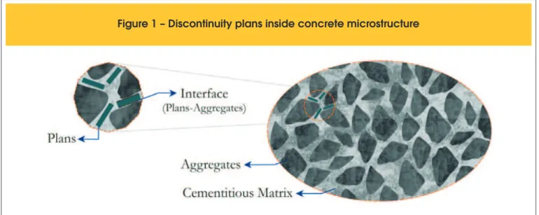
The application of Microplane Theory (Mohr [2], Taylor [3]) to modeling concrete structures is quite pertinent because the as-sociation between solid structure of the heterogeneous material
(cementitious matrix with aggregates of diferent particle sizes) and
the existence of multiple plans of discontinuities positioned at the interfaces of its grains (Figure 1).
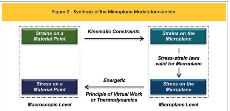
Although this association has been understood on a micro scale, Bažant and Gambarova [4] formulated a macro scale model based on such association. The model prescribes constitutive behavior in individual and independent microplanes and relates this local behavior with macro stresses and strains in order to represent the inelastic response of the material. After this pioneer work, many other microplane models has been proposed (Carol [5], Ožbolt [6], Carol [7], Leukart [8], Leukart and Ramm [9]). All of them follow the schema showed in Figure 2.
In a very general way, the formulation of Microplane Models fol-lows three main steps, as can be seen in Fig. 2. Given the macro-scopic strain tensor at a material point, kinematic constraints are imposed in order to calculate the strains on the microplanes. The
direction of each microplane is deined to be normal to the surface
of a sphere centered at the material point (Figure 3). After imposing such constraints, a local constitutive behavior is assumed in order to evaluate the local stresses as well as a microplane measure of
the material degradation. In the inal stage, macroscopic stresses
as well as the global constitutive tensor are evaluated after using an energy principle.
The model proposed by Leukart and Ramm [8] adopts (step 1) a decomposition of the macroscopic strain tensor into its volumet-ric and deviatovolumet-ric components (V-D split); (step 2) that the dam-age process is the main dissipation mechanism which describes the degradation on the material and that degradation is evaluated through a single equivalent strain combined with a single damage law; (step 3) that the free energy on the microplanes exists and its integral over all microplanes is equal to the macroscopic free energy of Helmholtz.
Wolenski [9] generalizes the computational implementation of Leu-kart and Ramm [8] proposition, in order to allow any microplane equivalent strain measure and any damage law. Such an
improve-ment has been impleimprove-mented in the context of the Uniied Compu -tational Environment, proposed by PENNA [11], on the INSANE system.
The numerical simulations presented in this paper use one of the options of the unified environment for microplane mod-els of the INSANE system. Specifically, the simulations uses volumetric-deviatoric strain split proposed by Leukart and Ramm [8] and the equivalent strain defined by de Vree [12], according to:
(1)
(
)
21 1
3
23
3
2
=
V+
V+
D DVree
k
k
k
p ph
e
e
e e
where
η
Vree is equivalent strain measure,ε
Vis volumetric part of the strain tensor,ε
p is the p component of the deviatoric strain tensor andk
1andk
2 are material parameters that relate toFigure 2 – Synthesis of the Microplane Models formulation
tensile and compression of concrete, and an exponential damage law, given by:
(2)
( )
{
0}
0
1
1
éë - ùû= -
- +
mic
d
k
a a
e
b k kk
where
d
mic is the damage measure,κ
is the current equivalent strain,κ
0 is a material parameter that speciies a limit forκ
refer-ring to the beginning of the damage process, and
a
andβ
are others material parameters.3. Reinforcement and bond-slip model
Reinforcement and bond-slip can be represented into reinforced
concrete FEM models according to three diferent approaches:
Smeared Reinforcement Models, Discrete Reinforcement Models (Ngo and Scordelis [13]) and Embedded Reinforcement Models (Balakrishna and Murray [14], Allwood and Bajarwan [15] and Elwi and Hrudey [16]).
As can be seen in de Castro [17], the two last approaches were implemented into the INSANE system resulting in a powerful tool for the analysis of reinforced concrete structural elements that al-lows the combination of any constitutive models for concrete and steel, as well as any bond stress-slip law.
The numerical simulations presented in this paper adopt the em-bedded reinforcement model proposed by Elwi and Hrudey [16], combining with the bond stress-slip laws proposed by Eligehausen [18] and Hawkins [19].
3.1 The inite element with embedded
reinforcement
The element proposed by Elwi and Hrudey [16] is composed of an arbitrary element with an embedded reinforcement segment, ac-cording to Figure 4 to the bidimensional case.
In this model, the normal strain in the tangent direction to the re-inforcement segment is provided by the sum of two components.
The irst one comes from the deformation of the concrete in the
tangent direction to the reinforcement segment and the second one comes from the slip of the reinforcement. The concrete strains
are directly obtained from the displacement ield of the plane i -nite element (the parent element) and the reinforcement slip is ob-tained by interpolating its values at the nodes of the steel segment.
The stifness matrix of the composed element is given by:
(3)
[ ]
[ ]
[ ] [ ] [ ]
é
ù
ê
+
ú
ë
û
bb bs sb ss cc
k
k
k
k
k
The sub matrix
[ ]
k
cc is due the constitutive model chosen for representing concrete and the matrices[ ]
k
ss ,[ ]
k
bb and[ ]
k
bsrepresent the contributions of steel and bond on the stifness of the
composite element, where:
(4)
[ ]
bb=
ò
(
{ }
b s+
{ }
b s b s)
s
k
y
E O
y
B E B A t ds
. .
(5)
t ds
. .
[ ] [ ]
bs=
sb T=
ò
{ }
b s s ss
k
k
B E B A
(6)
t ds
. .
[ ]
ss=
ò
{ }
s s s ss
k
B E B A
In the equations above, the integrals are performed over the line representing the reinforcement layer, and
ψ
contains the bond slip interpolation functions;E
b is the tangent module of the bond stress-slip law;O
s is the reinforcement perimeter per unit ofness;
B
b contains the derivatives of the bond slip interpolation functions relative to the tangent direction of the reinforcement lay-er;E
s is the tangent module of the stress-strain relation for the steel;A
s is the reinforcement area per unit of thickness;t
is the element thickness;B
s contains the derivatives of the interpolation functions of the parent element relative to the tangent direction of the reinforcement layer.3.2 Bond stress-slip laws
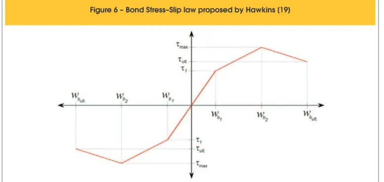
As said before, the laws proposed by Eligehausen [18] and Hawkins [19] where used in the numerical simulations presented in this paper. The law proposed by Eligehausen [18] is given by the equations (7) and is illustrated in Figure 5. Hawkins [19] proposed the trilinear law showed in Figure 6.
(7)
1æ
ö
=
ç
÷
è
ø
a b max
b
w
w
t t
for
0
£ ³
w w
b bmax,
=
maxt t
for
w w w
b1£ ³
b b2
,
(
)
23 1
æ
-
ö
=
-
-
ç
÷
-è
ø
b b max max f
b b
w w
w w
t t
t
t
for
w
b2£ ³
w w
b b3,
=
ft t
for
w w
b³
b3where
t
is the bond stress to a given slipw
b;t
max is the maxi-mum bond stress;t
f is the inal bond stress;w
b1 is the slipre-lated to the maximum bond stress;
w
b3 is the slip at the momentwhen the bond stress reaches its end point.
4. Experimental program
The experimental program, presented here, has been performed by Silva [1] and is also described in Silva [20]. The steel-concrete bond was evaluated on two concrete mixtures corresponding to strength classes
25
MPa
and45
MPa
(C25 and C45) and three diameters of the steel bars (8
mm
,10
mm
and12.5
mm
) (reinforced bars type CA-50, ABNT NBR 7480 [21]). For each combination described, six specimens were tested, totaling 108 pull-out tests.4.1 Materials
For the manufacture of concrete was used cement type CPV-ARI (high early strength Portland cement - ABNT NBR 5733 [22]) with
speciic mass of
3.05
g cm
/
³
, speciic apparent mass of0.90
g cm
/
³
and speciic surface area (Blaine) of4768 ² /
cm
g
. The ine aggregate was medium sand with ineness modulus of2.15
, speciic mass of2.61
g cm
/
³
, and maximum nominal size of4.75
mm
. The coarse aggregate was crushed basaltic, with ine -ness modulus equal to6.48
, speciic mass of2.90
g cm
/
³
and a maximum nominal size of19.0
mm
. The additive used was a poly-carboxylate-based third-generation superplasticizer, which accord-ing to the manufacturer has a density of1.08
g cm
/
³
, solid content of30
and a pH of4.42
.The slump was ixed at
10
±
2
cm
. In order to limit thew c
/
ratio it accepted superplasticizer additive content of0.26
in relation to the cement mass, for both concrete mixtures. Table 1 shows the mixture proportions of concrete C25 and C45.To analyze the mechanical properties of concrete were made cy-lindrical specimens with
10
cm
diameter and20
cm
high. For each rupture age three specimens were molded, according to ABNT NBR 5738 [23]. They were compacted using a vibrating table com-pleted in two concrete layers of 10s duration per layer. The curewas performed in a humid chamber at relative humidity above
95
and temperature of23
±
2º
C
.To characterize the concrete produced, compressive strength tests were performed according to ABNT NBR 5739 [24]; tensile strength of concrete by diametral compression according to ABNT NBR 7222 [25], and elastic modulus of elasticity of concrete, ac-cording to ABNT NBR 8522 [26]. Table 2 shows the results, indicat-ing the average and the standard deviation of the sample consist-ing of three specimens for each age and type of test.
The ribbed steel bars (type CA-50), used to generate the speci-mens for the bond tests, were characterized according to ABNT
NBR 7480 [21]. This standard speciies that the yield stress of the
steel bars is at least
500
MPa
and tensile strength is10%
greater than this value. For each diameter (8
mm
,10
mm
and12.5
mm
), three60
cm
long specimens were tested. The results are shown in Table 3.4.2 Experimental pull-out test
The Pull-Out Test (POT) is standardized by RILEM/CEB/FIB [27] and consists of plucking a steel bar integrated into a concrete
Table 1 – Mixture proportions of concrete
( kg / m
3)
Material C25 C45
Cement Portland 318.33 502.99 Fine aggregate 933.65 777.76 Coarse aggregate 958.09 977.01
Water 200.64 192.38
Superplasticizer 0.83 1.31
Water/Cement 0.61 0.37
Table 2 – Mechanical properties
of concrete
Mechanical
properties - concrete ( 28 days) C25 C45
Compressive strength - fcm (MPa) (Std. dev.)
27.8 (1.6)
49.3 (1.6) Tensile strength by diametral
compression - fctm (MPa) (Std. dev.)
3.28 (0.23)
4.60 (0.22) Elastic modulus - Ec (GPa)
(Std. dev.)
36.10 (2.82)
46.85 (0.28)
Table 3 – Characterization of the reinforced
bars with nominal diameter Ø (mm)
Properties 8.0 10.0 12.5
Yield stress fy (MPa) (Std. dev.)
625.0 (0.7)
620.0 (2.1)
580.0 (3.1) Tensile strength fst (MPa) 777.0
(3.5)
782.0 (1.4)
743.0 (2.6) Linear mass (kg/m) 0.398
(0.004)
0.610 (0.005)
Figure 7 – Characterization of the pull-out test
specimen. This test has aimed to study the relationship between bond stress and bond loss of the steel bar. Both ends of the bar are designed for out of the specimen, so that, the pull-out force is applied at one end while the bond loss is measured at the opposite end (Figure 7).
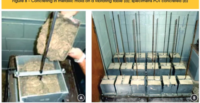
The specimen is cubic with dimension ten times the diameter of the bar (
10
Ø
), the minimum size is20
cm
and the bond length is ixed at ive times the diameter of the bar (5
Ø
). Figure 8 shows concreting in the metal mold on a vibrating table and the pull-out specimens.The system pull-out to method POT was mounted on a movable support properly leveled. For application of force was used a hy-draulic jack with a capacity of
600
kN
, connected to a manual pump pressure which was applied pulling force at one end of the bar, who reacted against the specimen. Figure 7 illustrates asche-matic with the method POT. The pullout force was measured by the load cell and the linear displacement by LVDT.
These data were collected through the data acquisition system (QuantumX) and visualized through the computer program (Cat-manEasy), both from HBM. With this system it was possible to ob-tain the force versus displacement curves.
The bond strength (
t
) is calculated according to Equation (8), whereF
is the pullout force and∅
is the diameter of the steel bar.(8)
25.
=
Æ
F
t
p
Figure 8 – Concreting in metallic mold on a vibrating table (a); specimens POT concreted (b)
5. Numerical simulations of pull-out test
The pull-out tests above described were simulated using the IN-SANE tools for the analysis of reinforced concrete. The microplane model proposed by Leukart and Ramm [8] combined with the
equivalent strain deined by de Vree [12] was used for representing
the concrete. The steel was represented by an elastoplastic stress-strain law inside the embedded reinforcement model proposed by Elwi and Hrudey [16], combined with the bond stress-slip laws pro-posed by Eligehausen [18] and Hawkins [19].
Figure 9 illustrates the inite element mesh adopted: 132 four-node quadrilateral inite elements (with 2 x 2 integration points) to repre -sent the concrete and 15 embedded reinforcement elements (with 2 integration points) to characterize the steel.
According the experimental data, the following material param-eters have been adopted: Young’s Modulus
=
36100
c
E
MPa
and Poisson ratio
=
0.15
c
ν
, for concrete C25; Young’s Modu-lus=
46850
c
E
MPa
and Poisson ratio=
0.20
c
ν
, for concrete C45; Young’s Modulus=
210000
s
E
MPa
and Yielding Stress625
=
yf
MPa
(8mm),=
620
y
f
MPa
(10mm),=
580
y
f
MPa
(12.5mm), for steel.
By itting the unidimensional behavior observed from the ex -perimental data, it was possible to obtain the numerical param-eters to the exponential damage law based on the equivalent
strain deined by de Vree [12]. The following values were found
(see equation 1 and 2):
a
=
0.950
,β
=
2200
, for concrete C25 and C45;0
=
0.000103
κ
,k
1=
0.630
andk
2=
0.2675
for C25; 0=
0.000103
κ
,k
1=
0.7556
andk
2=
0.1943
for C45.For consideration of bond loss, according to laws proposed by Eligehausen [18] and Hawkins [19], the parameters presented in Tables 4, 5, 6 and 7 were used (Figures 5 and 6).
Figure 9 – Finite element mesh for the pull-out test
Table 4 – Parameters for the Eligehausen bond
law for concrete C25
Table 5 – Parameters for the Eligehausen bond
law for concrete C45
Bar of 8.0 mm
wb1 = 0.75 mm wb2 = 1.25 mm wb3 = 5.00 mm
a = 0.40 mm tmax = 16.50 Mpa tf = 6.00 Mpa
Bar of 8.0 mm
wb1 = 0.30 mm wb2 = 1.00 mm wb3 = 5.00 mm
a = 0.40 mm tmax = 23.50 Mpa tf = 9.00 Mpa
Bar of 10.0 mm
wb1 = 0.45 mm wb2 = 1.00 mm wb3 = 5.00 mm
a = 0.40 mm tmax = 20.00 Mpa tf = 7.00 Mpa
Bar of 10.0 mm
wb1 = 0.30 mm wb2 = 1.00 mm wb3 = 5.50 mm
a = 0.40 mm tmax = 26.00 Mpa tf = 12.50 Mpa
Bar of 12.5 mm
wb1 = 0.30 mm wb2 = 0.90 mm wb3 = 5.00 mm
a = 0.40 mm tmax = 22.50 Mpa tf = 9.00 Mpa
Bar of 12.5 mm
wb1 = 0.30 mm wb2 = 1.00 mm wb3 = 6.00 mm
t1 = 11.50 mm tmax = 16.50 Mpa tult = 6.00 Mpa t1 = 17.00 mm tmax = 23.50 Mpa tult = 9.00 Mpa
Bar of 10.0 mm
wb1 = 0.10 mm wb2 = 0.75 mm wbult = 5.10 mm
t1 = 13.00 mm tmax = 20.00 Mpa tult = 7.00 Mpa
Bar of 10.0 mm
wb1 = 0.10 mm wb2 = 1.10 mm wbult = 5.20 mm
t1 = 23.50 mm tmax = 27.00 Mpa tult = 12.50 Mpa
Bar of 12.5 mm
wb1 = 0.10 mm wb2 = 0.60 mm wbult = 5.30 mm
t1 = 16.50 mm tmax = 22.50 Mpa tult = 9.00 Mpa
Bar of 12.5 mm
wb1 = 0.10 mm wb2 = 0.90 mm wbult = 6.10 mm
t1 = 27.50 mm tmax = 29.00 Mpa tult = 15.50 Mpa
Nonlinear simulations have been performed under the assump-tion of plane stress condiassump-tions and using generalized displacement control method (Yang and Shieh [28]), initial load factor equal to
0.080
and0.040
for Eligehausen [18] and Hawkins [19] bond laws, respectively, and tolerance of1 10
×
−4.The results of the numerical simulations, together the range of ex-perimental data, can be seen in Figure 10, referring to concrete C25 and C45, and to bar diameters of
8
mm
,10
mm
and12.5
mm
. Figure 10 shows good agreement between the experimental and numerical results for the six combinations of two concretes and three reinforcing bars. Both, the Eligehausen and Hawkins laws represented well the experimental range. Clearly, the Eligehausen law has represented better because of its nonlinear nature. This feature was very important, mainly for load levels near of the load limits, when the behavior is strongly nonlinear.The curves bond stress
×
slip for all simulations can be seen in Figure 11. By comparing Figures 11 and 10, it can be observedthat the curves load
×
slip (Fig. 10) and bond stress×
slip (Fig. 11) have the same shapes. It is also observed that the bond stress and slip limits of the Figure 11 are almost equals to the ones used as input values (Tables 4, 5, 6 and 7). These observations allows to conclude that structural behavior of the test and the local behavior of the concrete-steel interface are almost the same, high-lighting the pertinence of the RILEM’s test to study local interac-tions between the two materials. The observainterac-tions also allow con-cluding that, despite the sophistication of the constitutive model used for concrete, it was not so important for this FEM analysis. In spite of good agreement between experimental and FEM anal-ysis, as showed in Figure 10, the FEM results for C45-12.5mm were obtained using a lower limit of bond stress (29
MPa
). For all analysis performed with bond stress limit larger than29
MPa
the incremental-iterative process stops at the same load level (71.176
kN
), as illustrated in Figure 12 (points A and B).!!"#$ % &'%()*)+,%' %%
´
slip curves for Eligehausen (E) and Hawkins (H) bond laws
In order to explain this occurrence, Figure 13 shows the variation of the reinforcement force, bond stress and reinforcement slip, as well as the mesh’s deformed shape, corresponding to the points A (right images) and B (left images) of the Figure 12.
As can be seen in Figure 13, the maximum values for reinforcement force, bond stress and reinforcement slip are:
71.176
kN
,29.1177
MPa
and0.7603
mm
for point A (see Fig. 12), and70.590
kN
,28.9722
MPa
and0.8292
mm
for point B (see Fig. 12). These values, as well as the general behavior illustrated in Figure 13, are very close to the input data of Table 7, highlighting again the local nature of the phe-nomenon. Also, it is observed that the reinforcement force for point A (71.176
kN
) corresponds to the steel yield stress, according with experimental values (Table 3), and this is the reason because the in-cremental-iterative process stops. So, this analysis allows concluding that, for this case (C45-12.5
mm
), the reinforcement yielding limits the development of transfer mechanisms at the interface steel-concrete. Although, it was noted the occurrence, for all experimental tests for this case (C45-12.5
mm
), of the failure by pullout, the experimental values in Table 3, shows that this failure was on the threshold of the steel yield strength, contributing to the statement obtained from the numerical simulations presented.6. Final remarks
The numerical results obtained from the use of Microplane Consti-tutive Model combined with an Embedded Reinforcement Model and two bond stress-slip laws were compared with the experimen-tal results and a good agreement was observed.
Also was observed a good representation of the actual behavior of the RILEM/CEB/FIB [27] Pull-Out test, using the proposed combi-nation, highlighting the pertinence of the RILEM proposal to study the local behavior of the concrete-steel interface.
A correlation between numerical and experimental results and some parameters validates the proposed combination and
identi-ies the signiicance of such parameters on response.
So, it can conclude that such combination enables a realistic rep-resentation of the behavior of the bond loss between the reinforce-ment and concrete.
In the simulations of the RILEM’s tests presented in this paper, the concrete constitutive model was not so important due the local
nature of such tests. However, the combined efects of concrete
nonlinearity and bond-slip are very important and should always
be included in general inite element models because, in damaged regions, there are peaks of bond stress due to the intensiication of transfer efort at the interface between cracked areas and intact
ones.
Aiming to expand the knowledge about this theme, new simula-tions must be performed using the INSANE tools for reinforced concrete structures, such as: the extensive library of constitutive models for concrete, the discrete approach models for
reinforce-ment including interface inite elereinforce-ments for bond slip consideration.
7. Acknowledgements
The authors gratefully acknowledge the important support of
FAPEMIG (in Portuguese “Fundação de Amparo à Pesquisa de
Minas Gerais” - Grant PPM-00310-13), FAPESP (in Portuguese
“Fundação de Amparo à Pesquisa do Estado de São Paulo” -
Processo 08/57743-7) and of CNPq (in Portuguese “Conselho
Nacional de Desenvolvimento Cientíico e Tecnológico” – Grant
308785/2014-2).
8. Nomenclature
F - Pullout force (kN);
Ø - Diameter of steel bar (mm);
Ec - Elastic modulus of elasticity of concrete (GPa); POT - Pull-Out Test (RILEM/CEB/FIP RC6: 1983); fcm - Compressive strength of concrete average (MPa);
fctm - Tensile strength of concrete by diametral compression aver-age (MPa);
fy - Yield stress of steel (MPa); fst - Tensile strength of steel (MPa); t - Steel-Concrete Bond strength (MPa);
tmáx - Steel-Concrete Maximum bond strength (MPa); t1 - Steel-Concrete initial bond strength (MPa);
tult. - Steel-Concrete ultimate bond strength (MPa).
9. References
[1] SILVA, B. V. Investigação do Potencial dos Ensaios Apulot e Pull-Out para Estimativa da Resistência a Compressão do
Concreto. Master’s Thesis. Universidade Estadual Paulista (UNESP), Ilha Solteira, SP, Brazil, 2010.
[2] MOHR, O. Welche Umstände Bedingen die Elastizitätsgren-ze und den Bruch Eines Materiales? 1900. Cited in Leukart [7].
[3] TAYLOR, G. I. Plastic Strains in Metals. Journal of the Insti-tute of Metals, v. 62, p. 307-324, 1938. Cited in Leukart [7].
[4] BAŽANT, Z. P.; GAMBAROVA, P. G. Crack Shear in Con -crete: Crack Band Microplane Model. Journal of Structural Engineering, v. 110, p. 2015-2035, 1984.
[5] CAROL I.; JIRÁSEK M.; BAŽANT Z. P. A thermodynamically
consistent approach to microplane theory. I. Free energy and consistent Microplane stresses. International Journal of Sol-ids Structures, v. 38, p. 2921-2931, 2001.
[6] OŽBOLT J.; LI Y.; I. KOŽAR. Microplane model for concrete
with relaxed kinematic constraint. International Journal of Solids Structures, v. 38, p. 2683-2711. 2001.
[7] C AROL I.; JIRÁSEK M.; BAŽANT Z. P. A framework for
microplane models at large strain, with application to hyper elasticity. International Journal of Solids Structures, v. 41, p. 511-557, 2004.
[7] LEUKART, M. Kombinierte Anisotrope Schädigung und Plas-tizität bei Kohäsiven Reibungsmaterialien. Ph.D. Thesis, Universität Stuttgart, German, 2005.
[8] LEUKART, M.; RAMM, E. Identiication and Interpretation of
Microplane Material Laws. Journal of Engineering Mechan-ics, v. 132, p. 295-305, 2006.
[9] WOLENSKI, A. R. V. Ambiente Teórico-Computacional
Uni-icado para Modelos Constitutivos: Inclusão de Modelo de
Microplanos. Master’s Thesis. Universidade Federal de Minas Gerais (UFMG), Brazil, 2013.
[10] WOLENSKI, A. R. V.; MONTEIRO, A. B.; PENNA, S. S.;
Degradação Elástica: Uniicação Teórica, Proposta de Novo Modelo, Implementação Computacional e Modelagem de
Estruturas de Concreto. Ph.D. Thesis. Universidade Federal de Minas Gerais (UFMG), Brazil, 2011.
[12] de VREE, J. H. P.; BREKELMANS, W. A. M.; van GILS, M. A. J. Comparison of nonlocal approaches in continuum damage mechanics. Computer and Structures, v. 55, p. 581-588, 1995. [13] NGO, D.; SCORDELIS, A. C. Finite element analysis of re-inforced concrete beams. Journal of ACI, v. 64, p. 152-163, 1967.
[14] S. BALAKRISHNA; D. W. MURRAY. Prediction of response
of concrete beam sand panels by nonlinear inite element
analysis. IABSE Reports, p. 393-404, 1987.
[15] R. J. ALLWOOD; A. A. BAJARWAN, A new method for
mod-elling reinforcement and bond in inite element analysis of re -inforced concrete, International Journal of Numerical Meth-ods in Engineering, v. 26 p. 833-844, 1989.
[16] ELWI, A. E.; HRUDEY, T. M. Finite Element Model for Curved Embedded Reinforcement. Journal of Engineering Mechan-ics, v. 115, p. 740 754, 1988.
[17] de CASTRO, S. S. Framework Teórico e Computacional
para Estruturas de Concreto Armado: Implementação de Modelos de Armadura e Aderência. Master’s Thesis. Univer -sidade Federal de Minas Gerais (UFMG), Brazil, 2013. [18] ELIGEHAUSEN, R., POPOV, E. P., BERTORO, V. V.,
Lo-cal Bond Stress-Slip Relationships of Deformed Bars Under Generalized Excitations. Earthquake Engineering Research Centre, University of California, Berkeley, p. 169, 1983. [19] HAWKINS, N.; LIN, I. J.; JEANG, F. L. Local Bond Strength
of Concrete for Cyclic Reversed Loadings, 1982.
[20] SILVA, B. V.; BARBOSA, M. P.; SILVA FILHO, L. C. P.; LORRAIN, M. S. Experimental investigation on the use of steel-concrete bond tests for estimating axial compressive strength of concrete: part 1. Revista IBRACON de Estruturas e Materiais, v. 6, p. 715-736, 2013.
[21] ASSOCIAÇÃO BRASILEIRA DE NORMAS TÉCNICAS.
NBR 7480: Aço destinado a armaduras para estruturas de concreto armado - Especiicação. Rio de Janeiro, 2007 [In
Portuguese].
[22] ASSOCIAÇÃO BRASILEIRA DE NORMAS TÉCNICAS.
NBR 5733: Cimento Portland de alta resistência inicial. Rio
de Janeiro, 1991 [In Portuguese].
[23] ASSOCIAÇÃO BRASILEIRA DE NORMAS TÉCNICAS. NBR 5738: Concreto - Procedimento para moldagem e cura de corpos de prova. Rio de Janeiro, 2003 [In Portuguese]. [24] ASSOCIAÇÃO BRASILEIRA DE NORMAS TÉCNICAS.
NBR 5739: Concreto - Ensaios de compressão de corpos de
prova cilíndricos. Rio de Janeiro, 2007 [In Portuguese]. [25] ASSOCIAÇÃO BRASILEIRA DE NORMAS TÉCNICAS.
NBR 7222: Concreto e Argamassa - Determinação da re
-sistência à tração por compressão diametral de corpos de
prova cilíndricos. Rio de Janeiro, 2010 [In Portuguese]. [26] ASSOCIAÇÃO BRASILEIRA DE NORMAS TÉCNICAS. NBR
8522: Concreto - Determinação do módulo estático de elasti
-cidade à compressão. Rio de Janeiro, 2008 [In Portuguese].
[27] RILEM/CEB/FIB. Bond Test for Reinforcing Steel: Pull-Out Test - RC 6. Comité Euro-International Du Béton, Paris. 1983.
![Figure 5 – Bond Stress–Slip law proposed by Eligehausen [18]](https://thumb-eu.123doks.com/thumbv2/123dok_br/18860688.417878/5.892.60.839.183.555/figure-bond-stress-slip-law-proposed-eligehausen.webp)