Article
J. Braz. Chem. Soc., Vol. 26, No. 6, 1115-1123, 2015. Printed in Brazil - ©2015 Sociedade Brasileira de Química 0103 - 5053 $6.00+0.00
A
*e-mail: [email protected]
Effect of Applied Voltage on Slow-Release of Cu(II) Ions on the Synthesis of
Copper(II) Stearate Complex by Electrochemical Technique
Norazzizi Nordin,a Siti Z. Hasan,a Zuhailie Zakaria,a Noor A. Baharuddin,a
Wan Z. Samad,a Muhammad R. Yusopa,b and Mohamed R. Othman*,a
aSchool of Chemical Sciences & Food Technology, Faculty of Science & Technology,
Universiti Kebangsaan Malaysia, 43600 UKM Bangi, Selangor, Malaysia
bRegenerative Medicine Cluster, Advanced Medical & Dental Institute, Universiti Sains Malaysia,
13200 Kepala Batas, Pulau Pinang, Malaysia
An electrochemical technique based on the slow-release of Cu2+ ion from electrochemical oxidation of a Cu anode in the presence of stearic acid (HSt) and an aqueous solution of ammonium acetate (CH3COONH4)(0.1 mol L-1) as supporting electrolyte has been used to synthesize Cu(II) stearate (Cu(II)St) complex. Different values of applied voltages (1, 5 and 10 V) were used during the synthesis to study the effect of applied voltage on the particle size of the Cu nanoparticles and morphology of the synthesized Cu(II)St complex. By using 1 V of applied voltage, small Cu nanoparticle was produced with an average particle size of 2.49 ± 0.82 nm, followed by 5 V (3.61 ± 1.18 nm) and 10 V (6.64 ± 2.72 nm). Another advantage of using 1 V of the applied voltage is the formation of well-shaped petal-like structures of the Cu(II)St complex compared to the synthesis using 5 V and 10 V which inhibit the formation of well-shaped petal-like structure. This proves that the slow-release electrochemical synthesis using lower value of applied voltage has successfully resulted in the formation of small size Cu nanoparticles.
Keywords: electrochemical synthesis, Cu(II) complexes, applied voltage, nanoparticle
Introduction
Copper(II) carboxylates have received considerable attention during the last decades due to their special features in geometrical structures and physicochemical properties, and they have many applications in biochemistry and in industry. Cu(II) carboxylates have been applied as superhydrophobic coating materials,1,2 precursors in the
synthesis of metal-organic frameworks,3 and as molecular
templates in the synthesis of semiconductor nanorods.4 In
addition, Cu(II) carboxylates with nitrogen donor ligands have been reported to play an important role in fungal growth retardation activity for wood protection.5
The interest of these complexes derives from the diversity of its structure, as it can contain two or more antiferromagnetically coupled metal centers.6,7 Each
carboxylate oxygen atom in the complex has two lone electron pairs. The structural formation of the complex depends on the utilization of one or two lone electron pairs on the oxygen of the carboxylate group for bonding
to the Cu2+ ion. If only one lone electron pair is involved,
the result is a paddle-wheel dimer structure (Figure 1a). A polymeric structure (Figure 1b) may form if the second lone pair is donated to the Cu2+ ion of another paddle-wheel
dimer structure.
In such a dinuclear dimer, two Cu2+ ions are bridged
by four carboxylate groups of ligands. The coordination geometry around Cu atoms in the paddle-wheel dimer Cu(II) carboxylate is square pyramidal with D4h
Figure 1. Structure of (a) paddle-wheel dimer and (b) a polymeric dimer
symmetry.8 There are two axial positions in the
paddle-wheel dimer that can be occupied by a wide variety of ligand donors or electron pairs. The common axial ligands most reported in the literature are water,9 urea,10
pyridine-carboxylates,11 and organic acid.12 In many
cases, axial ligation of the paddle-wheel dimer prevents formation of inter-dimer bridges, due to donation of the lone electron pair of carboxylate oxygen to the Cu2+ ions
of the neighboring paddle-wheel dimer. Consequently, formation and precipitation of a paddle-wheel dimer with polymeric behavior can be avoided.13
Previous studies have reported that most of the complexes are synthesized using chemical methods. Often, Cu(II) sulfate is used to synthesize the complexes with corresponding carboxylic acid,1,7,10 though other
compounds of Cu(II) such as carbonate,14,15 oxide6 and
nitrate8 have been used. Other than Cu(II) salts, copper
plates also have been used as a Cu2+ ion source.2 In the
current paper, Cu(II)St complex was prepared using an electrochemical technique based on the reaction between Cu2+ ions from the electrochemical oxidation of Cu
anode with palm-based stearic acid (C18:0) to produce Cu(II)St complex.
This electrochemical technique offers several advantages in inorganic synthesis: (i) the ability to achieve oxidizing or reducing power that cannot be equaled by any ordinary chemical reagent; (ii) no contamination to a solution with a reducing agent (or oxidizing agent) and its corresponding oxidation (or reduction) product; (iii) the selectivity of the reaction can be influenced by the applied electrode potential; (iv) this method permits the preparation of many substances that cannot be prepared using conventional method.16 In addition, the particle size
of the Cu nanoparticles can be controlled by adjusting the current density.17-19 This method has been introduced by
Reetz and Hilbig20 in the synthesis of different kind of
nanoparticles of different shapes and sizes down to the cluster regime.
Slow-release in the electrochemical synthesis involves the application of applied voltage with a lower value to ensure the the metal ion from the anode slowly releases into the bulk solution. A small size Cu nanoparticles are expected to be produced by using this method. This means that the concentration of metal ions in the bulk solution is low and continuous throughout the synthesis process. In the present study, we focus on the electrochemical synthesis and characterization of Cu(II)St complex. The effect of slow-release synthesis using different values of applied voltages on the particles size and surface morphology of the electrochemically synthesized complex are also investigated in this study.
Experimental
Chemicals
All chemicals used were analytical grade and used without further purification. Stearic acid (HSt) with 99% purity was purchased from Systerm. Cu foil (99% purity) and ethanol (95% purity) was from Sigma-Aldrich. Ammonium acetate (CH3COONH4) was purchased from
Hamburg chemical GmbH.
Electrochemical synthesis of Cu(II) stearate
The Cu(II)St complex was synthesized using an electrochemical technique. The electrolysis system consisted of a Cu foil (3 × 1 cm, 0.1 cm thickness) as the anode and graphite rod (6.5 mm diameter, Johnson Matthey chemicals Ltd.) as the cathode in the presence of 0.1 mol L-1
CH3COONH4 as the supporting electrolyte solution. Prior to
synthesis, both anode and cathode were rinsed with distilled water and small amount of acetone. A direct current (DC) power supply (TTi PSU Bench CPX400A) was used throughout the electrochemical synthesis. Ethanol was used as the solvent to prepare the 0.1 mol L-1 HSt solution. The
acid solution was mixed with CH3COONH4 solution with the
ratio of 1:1 (v/v) into the simple and undivided electrolysis cell (100 mL capacity). The reaction was performed at room temperature (27 °C) for 4 hours.
The resulting complex precipitates as a blue solid in the organic phase and was then separated from the aqueous phase and washed with distilled water and ethanol to remove the impurities. The precipitate was then dried in an oven (50 °C) for 2 hours and allowed to dry at room temperature. To optimize the quality of the synthesized product, several operating parameters were tested such as type of supporting electrolytes, reaction times, applied voltages, and concentrations of supporting electrolyte. The effect of applied voltages on the particle size of the Cu nanoparticles formed and the morphology of the solid Cu(II)St complex conducted using different values of applied voltage (1, 5 and 10 V) is investigated. Analysis of electrochemically synthesized Cu(II)St: mp = 80-85 °C, yield = 99.2%, elemental analysis for CuC36H70O4 (636.21 g mol
-1) (calculated): C (67.95%),
H (11.99%), O (10.06%), Cu (10.00%); (found): C (67.34%), H (12.20%), O (10.36%), Cu (10.10%).
Instrumentation
including Fourier transform infrared spectroscopy (FTIR) (Perkin Elmer 1310) in the range of 4000-400 cm-1 in KBr
pellets, X-ray photoelectron spectroscopy (XPS) (AXIS Ultra ‘DLD’ by using second edition of Kratos software) and X-ray powder diffraction (XRPD) (Bruker AXS D8 Advance) and the diffraction angle were measured with the X-ray radiation of Cu Kα (40 kV, 40 mA). The concentration of Cu in the aqueous phase solution during the synthesis process was measured by inductively coupled plasma-optical emission spectrometry (ICP-OES) (Perkin Elmer Optima 4300DV) using 6 series of standard solutions (0.1, 0.3, 0.5, 1.0, 2.0 and 5.0 ppm) as the calibration method, while a CHNS analyzer (Fison EA 1108) was used to determine the elemental composition of the synthesized complex . The melting points were obtained in a capillary tube using an Electrothermal IA9100 melting point apparatus. The size and shape of the nanoparticles were observed using a transmission electron microscopy (TEM) (Philips CM12-12796) with an accelerating voltage of 100 kV. Samples were prepared on carbon-coated copper grids covered with a polyvinyl formal polymer by adding a drop onto the grid and evaporating the solvent (ethanol) in ambient condition. The size values were averaged over more than 120 nanoparticles from different TEM micrographs of the same sample. The surface characterization of Cu(II)St powder was observed by field emission scanning electron microscopy (FESEM) and energy-dispersive X-ray spectroscopy (EDX) (Merlin Compact). Platinum metal was used for sputtering process.
Results and Discussion
Mechanism for the electrochemical synthesis of Cu(II) stearate
The mechanism for the formation of Cu(II)St complex using a electrochemical technique is as follows:
Anode: Cuº → Cu2+ + 2 e− (1)
Cathode: 2 e− + 2 H
2O → H2 + 2 OH– (2)
2 OH− + 2 CH
3(CH2)16COOH →
2 H2O + 2 CH3(CH2)16COO
– (3)
Overall reaction: Cuº + 2 CH3(CH2)16COOH →
Cu[CH3(CH2)16COO]2 + H2 (4)
From the previous mechanism, Cu2+ ions (equation 1)
were generated in the aqueous phase solution (Scheme 1) at the positively charged anode. At cathode, OH− ions
were generated (equation 2) and directly reacted with HSt to form stearate ion (equation 3) in aqueous phase solution (Scheme 1). The reaction between Cu2+ ions and
CH3(CH2)16COO
– resulted in the formation of Cu(II)St in
the organic phase solution (equation 4).
Optimization of operating conditions
Optimization of operating conditions were conducted to identify the effect of applied voltage, supporting electrolyte concentration and electrolysis time on the corrosion of Cu anode. Supporting electrolytes are required in electrochemical synthesis to maintain a constant ionic strength, to decrease the resistance of the solution, and to eliminate electromigration effects.21 Common inorganic
salts including sodium chloride (NaCl), potassium nitrate (KNO3), ammonium chloride (NH4Cl), and ammonium
acetate (CH3COONH4) were used as supporting electrolytes
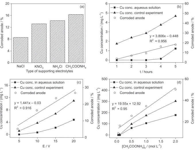
due to relatively low costs and high conductivities. The results showed that more Cu2+ ions were released
from the corroded anode into the aqueous phase of the CH3COONH4 supporting electrolyte solution, compared
to the other types of supporting electrolytes (Figure 2a). According to Mahoney and Mossaad,22 CH
3COONH4 is an
acceptable supporting electrolyte material that possesses high conductivity in electrochemical synthesis. Our results confirmed that CH3COONH4 provides better conductivity
and the highest efficiency in the electrochemical synthesis process.
Electrolysis time is one of the major concerns in chemical synthesis, since longer times may lead to higher energy consumption. In the current study, increases in reaction time generally resulted in increased corrosion of the anode (Figure 2b circle symbol), which produced more Cu2+ ions in the aqueous phase solution. For 0.1 mol L-1 of
HSt, the Cu concentration was generally very low for the first 3 hours due to its use in the formation of the Cu(II)St complex (Figure 2b square symbol). After 3 hours, no more free fatty acid was available in the organic phase and an excess of available Cu2+ ions was created in solution. Since
unnecessarily long reactions times will result in increased costs due to excess energy consumption and wasted metal species in the aqueous phase, a 4-hour electrolysis time was considered to be the ideal duration to completely react
Scheme 1. Mechanism for the electrochemical synthesis of Cu(II)St
the fatty acid with Cu2+ ions and less wasted Cu species.
Electrolysis of CH3COONH4without fatty acids (Figure 2b
triangle symbol) was performed as a control experiment to prove that increasing the reaction time produced more Cu2+ ions in the aqueous phase solution.
High cell voltages should not be used during electrochemical synthesis to avoid losses of energy, high temperatures, and electrode damage.23 Selection of the
correct supporting electrolyte at an appropriate concentration can assist in minimizing the applied voltage for the electrochemical synthesis process. In the current study, increases in the applied voltage were observed to increase the corrosion percentage of the Cu anode (Figure 2c circle symbol). In the synthesis of Cu(II)St (Figure 2c square symbol), full utilization of fatty acids was achieved with the use of 10 V of applied voltage after 4 hours, without formation of excess Cu2+ ions. At 5 V, no excess Cu2+ ions
formed in solution, but higher concentrations of HSt were still present, and thus the total reaction time at 5 V would possibly be greater than 4 hours. Application of even higher voltages (> 15 V) may reduce the total reaction time but also
increase the potential to form certain by-products such as Cu(II) oxides.22 Therefore, we concluded that 10 V was the
ideal applied voltage for the synthesis of Cu(II)St to prevent the formation of undesired compounds.
The main purpose of adding CH3COONH4during
the synthesis process is to increase the electrolytic conductivity of the electrochemical system, which in turn affects the current efficiency, cell voltage, and energy consumption in the electrolytic cell.24 Increasing the
concentration of CH3COONH4in the current work was
observed to increase the corrosion percentage of Cu anode (Figure 2d circle symbol), which resulted in an increase in the Cu2+ concentration. Based on our results, the ideal
concentration was 0.1 mol L-1 CH
3COONH4for 4 hours of
reaction time (Figure 2d square symbol). Further increases in CH3COONH4concentration produced excess Cu
2+
ions. A major drawback of using high concentrations of CH3COONH4(e.g., > 0.5 mol L
-1) in the electrochemical
synthesis process is heavier cathode plating results.22
Therefore, we determined that a 0.1 mol L-1 CH
3COONH4
solution was the appropriate concentration of supporting
0 4 8 12 16 20
Corroded anode / %
Type of supporting electrolytes
NaCl KNO3 NH Cl4 CH COONH3 4
(a)
1 2 3 4 5
0 1 2 3 4 5 6
Cu conc. aqueous solution
Cu conc. control experiment
Cu concentration / (mg L
)
-1
t / hours
0 10 20 30 40 50 60 Corroded anode
Corroded anode / %
Corroded anode / %
y = 3.806x – 0.448
y = 19.55x + 12.92
R = 0.9562
R = 0.952
(b)
Cu concentration / (mg
L
)
-1
Corroded anode /
%
y = 1.441x – 0.03 R = 0.9162
(c)
5 10 15 20
0 4 8 12
16 Cu conc. in aqueous solution Cu conc. control experiment
E / V
0 10 20 30
Corroded anode
0.0 0.5 1.0 1.5 2.0
0 100 200 300 400 500
Cu conc. in aqueous solution Cu conc. control experiment
[CH COONH ] / (mol L )3 4 o -1
20 40 60
Corroded anode
(d)
Cu concentration / (mg
L
)
-1
Figure 2. Effects of (a) type of supporting electrolytes; (b) electrolysis times; (c) applied voltages and (d) supporting electrolyte concentrations
on percentage of corroded anode (a-d) and Cu2+ ion concentration (b-d) in aqueous solution during electrochemical synthesis of Cu(II)St complex.
electrolyte to be used in electrochemical synthesis of Cu(II)St.
Effect of applied voltages on the synthesis of Cu(II) stearate complex
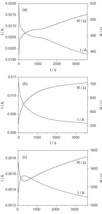
Figure 3 shows the effect of different applied voltages on current and resistance during the electrochemical synthesis of Cu(II)St complex for 60 min. According to Ohm’s law (voltage = current × resistance), voltage is
directly proportional to the generated current (I). The value of It = 0 (21.72 mA) in Figure 3a using 10 V of the
applied voltage is the highest compared to other applied voltages (10.70 mA for 5 V (Figure 3b) and 1.36 mA for 1 V (Figure 3c)). This shows that the use of high voltage will directly increase current flows and thus increase the Cu anode corrosion to produce more Cu ions for complex formation. This result was in line with the result explained in Figure 2c.
Graph of I vs. t in Figure 3c is different from the others in which there is a current “spike” during the first 6 minutes of the synthesis process (It = 0 = 1.36 mA;
It = 6min = 1.58 mA). The application of 1 V of applied
voltage during the synthesis reduces the generated Cu2+
ions in the bulk solution thus slows the rate of complex formation. Therefore, 6 minutes are required to produce sufficient concentration of Cu2+ ions to initiate the Cu(II)St
formation. After 6 minutes, the graph shows a gradual decay in the current until the end of the electrolysis. Graph of R vs. tin Figure 3c shows that after 6 min, the resistance (Ω value) was increased towards the end of the electrolysis. This is due to the continuous production of Cu2+ ions in the
solution and causing the increase of complex formation. The Cu(II)St complex produced is not electricity conductor, resulting in a decrease in current flows, while the resistance is increasing. In contrast with the synthesis using 10 and 5 V of applied voltages (Figures 3a and 3b), there is a gradual decay in the current while increasing the resistance from the beginning until the end of the reaction time. This demonstrates the ability of these applied voltages to produce a higher concentration of Cu2+ ions which is
sufficient to initiate the complex formation and increase the rate of complex formation.
The effect of applied voltages on the generation of Cu2+
ions concentration in aqueous phase solution was studied using Faraday equation based on the data obtained in Figure 3. Faraday equation is as follows:
AQ m
zF
= (5)
where m = mass of dissolved Cu (g); A = relative atomic mass (g mol-1); Q = charge (C); z = number of charges; and
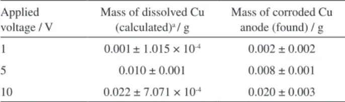
F = Faraday constant (96 485 C mol-1). Table 1 (calculated)
shows the mass of dissolved Cu in solution after 60 min of electrolysis was highest using 10 V of applied voltage, followed by 5 V and 1 V. These results are in accordance with the conclusions of the results from Figure 3 and 2c, in which the increase of applied voltage increases the corrosion of Cu anode. To support the results obtained in Table 1 (calculated), Cu anode was weighed before and after electrolysis to determine the mass of corroded
0 1000 2000 3000
0.0195 0.0200 0.0205 0.0210 0.0215 0.0220
t / s
I / A
I /
A
I /
A
I /
A
(a)
460 480 500 520
0 1000 2000 3000
0.008 0.009 0.010 0.011
I / A
t / s (b)
550 600 650 700
0 1000 2000 3000
0.0012 0.0014 0.0016 0.0018
I / A
t / s (c)
1000 1200 1400 1600
R / Ω R / Ω R / Ω
R /
Ω
R /
Ω
R /
Ω
Figure 3. Effects of applied voltages on resulting current and resistance
in the synthesis of Cu(II)St complexes using (a) 10 V; (b) 5 V and (c) 1 V of applied voltage. [HSt]o = 0.1 mol L-1; [CH
3COONH4] = 0.1 mol L-1;
anode. The results obtained are summarized in Table 1 (found). The mass of corroded anode that we found in this experiment is not that different from the calculated ones using Faraday equation. Therefore, we can conclude there are no significant differences from the result obtained in this study with the calculated value.
Characterization of electrochemically synthesized Cu(II) stearate
A peak at 1697 cm-1 was observed on the IR spectrum
of HSt (Supplementary Information, Figure S1), and this was assigned to the stretching vibration of the carboxylate group of HSt.1 For both spectra, the presence
of peaks at wavenumbers 2800-3000 cm-1 represented the
asymmetric (vas) and symmetric (vs) stretching vibrations
of the methyl and methylene groups of fatty acid ligands.6
The asymmetric and symmetric stretching vibrations of the coordinate carboxylate groups appeared at 1589 and 1424 cm-1, respectively. These bands are characteristic of
dicopper tetracarboxylate complexes.6
Several authors6-8 have proposed that the positions of
asymmetric (vas) and symmetric (vs) stretching vibrations of carboxylate groups (∆v
COO = vCOO,as−vCOO,s) can be used to
distinguish the type of carboxylate-to-metal complexation structure of Cu(II) carboxylates. A value of ∆v
COO in the
range of 150-170 cm-1 corresponds to a bridging bidentate
Cu(II) coordination, while ∆v
COO > 200 cm-1 is an indication
for complexes with monodentate carboxylic groups.8 In
the IR spectrum in Figure S1, vCOO,as = 1588 cm-1 while
vCOO,s = 1421 cm-1, giving the value of ∆v
COO = 167 cm -1.
This value corresponded to a bridging bidentate mode of coordination and was in agreement with the results from previous studies. This proved that the desired complex have been synthesized.
From the XPS spectrum in (Supplementary Information, Figure S2a), the synthesized complex was composed of C, O and Cu element. The content of carbon is very high (about 69.48%) compared to other elements due to the presence of carbon chain of HSt. The binding energies were referenced to the C1s line at 284.5 eV from adventitious carbon. Deconvolution of C1s peaks showed the existence of
different carbon species in the electrochemically synthesized Cu(II)St complex. The XPS spectrum of C1s (Supplementary Information, Figure S2b) shows that there are three types of carbon in the synthesized complex which are fitted to the −C=O (288.2 eV) and –C−C (285.5 eV) while peak at 284.5 eV corresponds to carbon of HSt chain (–C−H).25
The XRPD patterns of HSt and Cu(II)St (Supplementary Information, Figure S3) were verified by comparison to the HSt file (JCPDS No. 04-0364) and Cu(II)St file (JCPDS No. 55-1622). Well-defined diffraction peaks were observed for both patterns, and thus both of the samples crystallized into layered structures. The peak cluster between 15-20° in the patterns of Cu(II)St has been reported for HSt.26 These
cluster peaks for HSt are slightly shifted to a lower angle after complex formation. The peak at low angles 1.76° for HSt was shifted to a lower angle (1.57°) after formation of Cu(II)St. This result proved that crystal formation occurred between Cu2+ ions and HSt ligands.
Particle size analysis
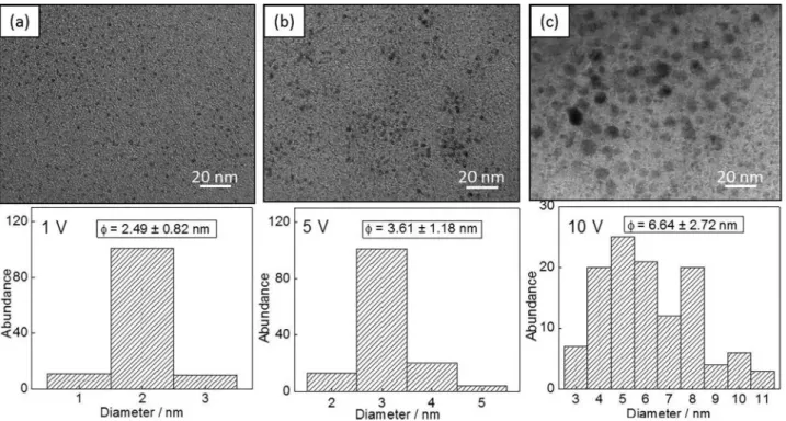
A TEM micrographs obtained for Cu samples shows the presence of small Cu clusters forming aggregates of different size (Figure 4). The micrograph in Figure 4a shows the formation of small size particles in the range of 1-3 nm with an average particle size of 2.49 ± 0.82 nm during the synthesis of Cu(II)St using 1 V of applied voltage. In contrast to the synthesis using 5 and 10 V (Figures 4b and 4c), the particles formed are bigger in size with an average particle size are 3.61 ± 1.18 nm and 6.64 ± 2.72 nm respectively. This indicates that the particle size of the synthesized product can be controlled by adjusting the applied voltage during the synthesis process as was reported by several researchers.27,28
Application of high applied voltage (i.e., 10 V) during the synthesis increases the generation of Cu particles in the bulk solution. Consequently, the particles have a tendency to agglomerate and being traps within the ligand used and resulting in larger particle size.27 In Figure 4a, fewer
particles are agglomerate as a result of less generation of Cu particles in the synthesis using 1 V. This is the advantage of slow-release electrochemical synthesis using lower applied voltage (i.e., 1 V) in which the Cu ion generated from the Cu anode are slowly released into the bulk solution containing HSt. Thus, less agglomeration occurred and small particles size of the metal is obtained.
Surface morphology analysis
Based on the FESEM micrographs, the electrochemically synthesized Cu(II)St complexes formed petal-like
Table 1. Mass of dissolved Cu (calculated and found)
Applied voltage / V
Mass of dissolved Cu (calculated)a / g
Mass of corroded Cu anode (found) / g
1 0.001± 1.015 × 10⁻⁴ 0.002 ± 0.002
5 0.010 ± 0.001 0.008 ± 0.001
10 0.022 ± 7.071 × 10⁻⁴ 0.020 ± 0.003
structures (Figure 5). This result is in accordance with other results already reported in the literature.1,2 The synthesis
of Cu(II)St complex using different values of applied voltages produces different size of Cu(II)St complex cluster. Figure 5a shows that by using 1 V of applied voltage, the cluster formed are larger in size, followed by 5 V (Figure 5b) and 10 V (Figure 5c). The cluster formed
using high applied voltage (10 V) seems to be broken into small pieces as in Figure 5c. Consequently, the cluster size of the complex is smaller than Figure 5b followed by Figure 5a. This might be the consequence of consumption of high applied voltage as it inhibits the formation of a well-shaped petal-like structure. EDX analysis was performed to determine the distribution of elements on the surface of
Figure 4. TEM images and size distribution of Cu nanoparticles synthesized using (a) 1 V; (b) 5 V; and (c) 10 V of applied voltage; magnification = 160000×.
Figure 5. FESEM micrograph of synthesized Cu(II)St with 20000× magnification using (a) 1 V; (b) 5 V; (c) 10 V of applied voltage and (d) EDX spectrum
the complex. The result obtained in Figure 5d proved that the synthesized complex composed of C, O and Cu. This result was in line with the result obtained by XPS analysis in Figure S2a (Supplementary Information).
Conclusions
The release of Cu2+ ions into the aqueous solution depends
on the type and concentration of supporting electrolytes, reaction times, and applied voltages. Ammonium acetate (CH3COONH4) was determined to be the best supporting
electrolyte in the electrochemical synthesis of Cu(II)St complex. Meanwhile, increases in the reaction time, applied voltage, and concentration of CH3COONH4 resulted in
the increased concentration of Cu2+ ions in the aqueous
phase solution, and thus enhanced the efficiency of the complex formation and reduced the energy consumption. The characterization using FTIR, XPS and XRPD proved that the synthesized complex was the desired Cu(II)St complex. The results from spectroscopic studies using FTIR and XPS confirm the presence of bonding between the coordinated carboxylate group of HSt with Cu2+ ions.
To study the effect of applied voltages on the particle size of the Cu nanoparticles produced, the applied voltage of the electrolysis process was varied which is 1, 5 and 10 V. The particle size analysis using TEM showed that the synthesis using 1 V of applied voltage produces small Cu cluster with an average particle size of 2.49 ± 0.82 nm while by using 5 V and 10 V, the resulting Cu cluster are much bigger in size which is 3.61 ± 1.18 nm and 6.64 ± 2.72 nm, respectively. In addition, the synthesis using 1 V of applied voltage formed petal-like structure whereas higher values of the applied voltage inhibit the formation of well-shaped petal-like structure. This proves that the small Cu cluster was successfully obtained in the slow-release electrochemical synthesis of Cu(II)St complex using 1 V of applied voltage. The results of this study can potentially be used to investigate the synthesis of other divalent metal complexes of interest to chemistry, biochemistry and industry.
Supplementary Information
Supplementary information is available free of charge at http://jbcs.sbq.org.br as PDF file.
Acknowledgements
The funding from Universiti Kebangsaan Malaysia through grants AP/2012/017, DLP-2013-002 and DPP-2013-045 are gratefully acknowledged. We wish to express special thanks to Ministry of Education of Malaysia
for postgraduate scholarship (MyBrain15) and Centre for Research & Instrumentation Management (CRIM), UKM for XRPD, XPS and FESEM analyses.
References
1. Chen, L.; Meng, H.; Jiang, L.; Wang, S.; Chem. - Asian J. 2011, 6, 1757.
2. Wang, S.; Feng, L.; Jiang, L.; Adv. Mater. 2006, 18, 767. 3. Papaefstathiou, G. S.; MacGillivray, L. R.; Coord. Chem. Rev.
2003, 246, 169.
4. Mao, G.; Dong, W.; Kurth, D. G.; Mohwald, H.; Nano Lett.
2004, 4, 249.
5. Kozlevcar, B.; Lah, N.; Makuc, S.; Segedin, P.; Acta Chim. Slov.
2000, 47, 421.
6. Doyle, A.; Felcman, J.; Teresa, M.; Braganc, M. L.; Polyhedron
2000, 19, 2621.
7. Iqbal, M.; Ali, S.; Muhammad, N.; Sohail, M.; Polyhedron2013, 57, 83.
8. Wojciechowski, K.; Bitner, A.; Bernardinelli, G.; Brynda, M.;
Dalton Trans.2009, 7, 1114.
9. Vaughan, G. B. M.; Sghmidt, S.; Poulsen, H. F.; Z. Kristallogr.
2004, 219, 813.
10. Kozlevcar, B.; Leban, I.; Petric, M.; Petricek, S.; Roubeau, O.; Reedijk, J.; Segedin, P.; Inorg. Chim. Acta2004, 357, 4220. 11. Jaskova, J.; Miklos, D.; Korabik, M.; Jorik, V.; Segl’a, P.;
Kalinakova, B.; Hudecova, D.; Svorec, J.; Fischer, A.; Mrozinski, J.; Lis, T.; Melnik, M.; Inorg. Chim. Acta2007, 360, 2711.
12. Goto, M.; Kani, Y.; Tsuchimoto, M.; Ohba, S.; Matsushima, H.; Tokii, T.; Acta Crystallogr., Sect. C: Cryst. Struct. Commun.
2000, 56, 7.
13. Wojciechowski, K.; Kucharek, M.; Buffle, J.; J. Membr. Sci.
2008, 314, 152.
14. Ramos Riesco, M.; Martınez Casado, F. J.; Lopez-Andres, S.; Garcıa Perez, M. V.; Redondo Yelamos, M. I.; Torres, M. R.; Garrido, L.; Rodrıguez Cheda, J. A.; Cryst. Growth Des.2008, 8, 2547.
15. Ramos Moita, M. F.; Duarte, M. L. T. S.; Fausto, R.; Spectrosc. Lett. 1994, 27, 1421.
16. Jolly, W. L.; The Synthesis and Characterization of Inorganic
Compounds, 1st ed.; Prentice-Hall: New Jersey, 1970.
17. Rodriguez-Sanchez, L.; Blanco, M. C.; Lopez-Quintela, M. A.;
J. Phys. Chem. B2000, 104, 9683.
18. Khaydarov, R. A.; Khaydarov, R. R.; Gapurova, O.; Estrin, Y.; Scheper, T.; J. Nanopart. Res.2009, 11, 1193.
19. Vilar-Vidal, N.; Blanco, M. C.; Lopez-Quintela, M. A.; Rivas, J.; Serra, C.; J. Phys. Chem. C2010, 114, 15924.
20. Reetz, M. T.; Helbig, W.; J. Am. Chem. Soc.1994, 116, 7401. 21. Plambeck, J. A.; Electroanalytical Chemistry: Basic Principles
22. Mahoney, D. M.; Mossaad, G. S.; US pat. 5,443,6981995. 23. Sakalis, A.; Fytianos, K.; Nickel, U.; Voulgaropoulos, A.; Chem.
Eng. J.2006, 119, 127.
24. Sengil, I. A.; Ozacar, M.; J. Hazard. Mater. 2009, 161, 1369 25. Deng, D.; Qi, T.; Cheng, Y.; Jin, Y.; Xiao, F.; J. Mater. Sci.:
Mater. Electron. 2014, 25, 390.
26. Corbeil, M. C.; Robinet, L.; Powder Diffr. 2002, 17, 52.
27. Saito, G.; Wan Mohd Azman, W. O. S.; Nakasugi, Y.; Akiyama, T.; Adv. Powder Technol.2014, 25, 1038.
28. Long, Y. M.; Zhao, Q. L.; Zhang, Z. L.; Tian, Z. Q.; Pang, D. W.;
Analyst2012, 134, 805.
Submitted:November 28, 2014