A
r
ti
c
le
*e-mail: [email protected]
Application of a Composite Polymer Electrolyte Based on Montmorillonite
in Dye-Sensitized Solar Cells
Bruno Ieiri Ito, Jilian Nei de Freitas, Marco-Aurelio De Paoli and Ana Flávia Nogueira*
Laboratório de Nanotecnologia e Energia Solar, LNES, Instituto de Química, Universidade Estadual de Campinas, CP 6154, 13084-971 Campinas-SP, Brazil
Neste trabalho um eletrólito polimérico nanocompósito baseado em uma argila do tipo montmorilonita e um polímero derivado do poli(óxido de etileno) plastificado com G-butirolactona foi preparado e caracterizado. Apesar da adição de plastificantes à matriz polimérica aumentar a condutividade iônica de eletrólitos poliméricos, a adição de grande quantidade desses aditivos compromete as propriedades mecânicas do sistema, de tal maneira que o ganho em condutividade não compense a perda na natureza “sólida” do meio eletrolítico. Filmes do eletrólito nanocompósito contendo diferentes concentrações de argila foram caracterizados por análise térmica e mecânica e por espectroscopia de impedância eletroquímica. A adição de montmorilonita resultou numa melhora das propriedades mecânicas do eletrólito, além de contribuir para um aumento da condutividade iônica do sistema. O eletrólito compósito foi aplicado em uma célula solar de TiO2/corante pela primeira vez, resultando em um dispositivo com eficiência superior a 3% sob irradiação de 10 mW cm-2.
In this work we report for the first time the preparation and characterization of a novel composite polymer electrolyte based on montmorillonite clay and a poly(ethylene oxide) derivative plasticized withG-butyrolactone and its application in dye sensitized solar cells. Although the plasticizers enhance the ionic conductivity of the polymer electrolytes, they compromise the mechanical stability of the whole system and make the practical application of these devices difficult. Films with composite polymer electrolytes containing different clay content were analyzed by thermal and mechanical analysis and electrochemical impedance spectroscopy. We observed that the addition of the inorganic particles to the polymer matrix promotes not only an enhancement in the mechanical properties but also contributes to the increase the of ionic conductivity of the system. A solid-state dye-sensitized solar cell was assembled for this first time with the electrolyte containing montmorillonite clay, displaying efficiencies higher than 3% at 10 mW cm-2.
Keywords: MMT clay, composite polymer electrolyte, ionic conductivity, dye sensitized
solar cells
Introduction
Since Grätzel’s announcement of the first dye-sensitized nanocrystalline solar cells (DSSC)1 as promising, low
cost, clean, and highly efficient devices for solar energy conversion, many groups have focused their efforts on improving and comprehending this technology in its different aspects. The liquid electrolyte usually employed in this cell is still a drawback for long-term practical operation due to electrolyte leakage or evaporation. It makes the large scale production difficult and causes substantial problems to bring DSSC onto the market. To overcome these problems,
many research groups have been searching for alternatives to replace the liquid electrolytes, such as inorganic or organic hole conductors,2-4 ionic liquids,5,6 polymer7-9 and
gel electrolytes.10-14
Our group has been working on DSSC using polymer electrolytes based on copolymers of poly(ethylene oxide) (PEO) derivatives since 1996 and the first results were published in 1999.15 The best solar energy conversion
efficiency obtained for a solid-state DSSC (1 cm2of
active area) was 2.6% under 10 mW cm-2 and 1.6% under
100 mW cm-2.16 Polymer electrolytes, however, present
lower ionic conductivity (10-5 S cm-1), and thus compromise
alternative to increase the ionic conductivity of a polymer electrolyte is the addition of plasticizers, which are low molecular weight organic liquids or oligomers, that increase the flexibility of the polymer chains (e.g. increase the free
volume), enhancing the mobility of the ionic species.17 Our
laboratory has been working with success on DSSC using plasticized polymer electrolytes as substitute for the liquid component since 2004.18-20 However, plasticizers also cause
losses in the mechanical properties of the entire system, leading to the formation of “gel-type” electrolyte, rather than a solid-state polymer electrolyte.
In this context, the introduction of inorganic particles to polymer electrolytes has become an interesting alternative. The addition of such particles enhances the thermal and mechanical stability of such materials and in some cases increases the ionic conductivity.21 Several
groups working in this area have used this approach with the introduction of inorganic nanofillers,22,23 and hybrid
organic-inorganic electrolytes (i.e. ionic liquids together
with nanoparticles)24-26 has become a common route to
elaborate polymer (or gel) electrolytes with improved ionic conductivity and mechanical properties.
Lithium batteries have become the main aim of polymer electrolyte researchers. The addition of inorganic particles such as hectorite,27,28 smectite,29 fumed silica,30,31 and
montmorillonite clay (MMT)32-34 provides both an increase in
the ionic conductivity and an improvement in the mechanical properties. Electrolytes containing silica nanoparticles have also been used to assemble dye-sensitized solar cells, leading to remarkable performances.31,35 Particularly, composite
polymer electrolytes (CPE) based on organophilic clays have received considerable attention in the last years. Homminga
et al.36 reported the addition of an organic modified MMT
to PEO and investigated the influence of the MMT in the crystallization of the polymer. It was shown that the silicate layers act as nucleating agents for the crystallization of PEO, but at high MMT contents a retarding effect on the crystal growth was observed. In another work, Wang et al.37reported an increase in the melting temperature of the
polymer electrolyte based on poly(vinylidene fluoride-hexafluoropropylene) containing modified MMT due to the formation of chemically distinct high-melting complexes attributed to the interaction between the silicate layers and the polymer chains. Despite the interesting results obtained so far, CPE containing MMT clay derivatives have not been applied to solar cells devices.
In this work we report for the first time the preparation and characterization of a composite polymer electrolyte based on the copolymer poly(ethylene oxide-co-epichlorohydrin),
(P(EO-EPI), the plasticizer G-butyrolactone (GBL), a commercial modified montmorillonite clay, LiI and iodine.
This electrolyte was tested in a solid-state dye sensitized solar cell (DSSC). The incorporation of the clay in the polymer electrolyte, containing 50 wt.% of GBL, improved both the ionic conductivity and the mechanical properties. A solid-state dye-sensitized solar cell was assembled displaying efficiencies higher than 3% at 10 mW cm-2.
Experimental
Materials
Poly(ethylene oxide-co-epichlorohydrin) samples were used as received from Daiso Co. Ltda (Osaka). The ethylene oxide/epichorohydrin ratio in the copolymer was 87/13 and the molar mass was ca. 1 x 10⁶ g mol-1, according to
the supplier. LiI, I2, the plasticizer GBL (Aldrich, 99%) and the quaternary ammonium salt modified MMT clay (Viscogel® S7, Bentec) were used as received without prior purification.
Preparation of the composite polymer electrolyte
The CPE were prepared by the dissolution of the polymer, LiI, I2 and GBL in acetone. Different contents of MMT clay (0, 1, 3, 5, 7 and 23 wt.%) were dispersed separately in ethylene glycol by sonication and then added to the polymer solution. The solutions were stirred for three days to fully dissolve all the components before use. In all samples, the clay content is expressed in relation to the weight of polymer + plasticizer.
Ionic conductivity measurements
Ionic conductivity measurements were evaluated as a function of MMT content in the CPE. The CPE films were prepared by casting the solution onto Teflon disks, and slowly dried with P2O5 under vacuum until homogeneous and free standing films were obtained. The resulting films were then kept in vacuum for 24 h before the impedance measurements. Conductivity measurements were carried out in the dry box MBraum150M (humidity < 10-4 %,
under an argon atmosphere). The films were fixed between two mirror-polished stainless steel disk shaped electrodes (diameter = 12 mm) and the conductivity values were calculated from the data obtained by electrochemical impedance spectroscopy (EIS), using an Eco-Chemie Autolab PGSTAT 12 with FRA module coupled to a computer in the frequency of 106 to 10 Hz and amplitude
Differential Scanning Calorimetry (DSC)
The DSC curves for the CPE were obtained on a T.A. Instruments Thermal Analyzer 2910, according to the following procedure: (1) Heating to 100 °C at 10 °C min-1
with an isotherm of 5 min; (2) Cooling to -100 °C at 10 °C and (3) Heating until 100 °C at 10 °C min-1. All procedures
were performed under argon flow (50 mL min-1). The data
presented in this work corresponds to the step 3.
X-ray diffraction (XRD)
The X-ray diffraction analyses were performed in the X-ray Diffractometer Shimadzu XRD6000 employing a radiation source of CuKA of 1.54 Å. The voltage and current intensities were 40.0 kV and 30.0 mA, respectively. The interlamellar distances were calculated from Bragg’s equation.
Thermomechanical analysis (TMA)
The TMA measurements were carried out in a Thermomechanical Analyser TMA 2940, under constant temperature of 25 °C, with an applied force ramp from 5 mN to 1 N on the compression mode, at a rate of 5 mN min-1.
Solar cell assembly and characterization
Devices were assembled with 0.25 cm2 of active area.
A blocking and compact TiO2 layer was spin-coated from a colloidal suspension of TiO2 nanoparticles onto the TCO glass substrate and heated to 450 °C for 30 min (fluoride doped tin oxide, Hartford Glass Co, Inc, 8-127 . This layer was covered with a TiO2 nanoporous film prepared by doctor blading using the commercial suspension (Nanoxide-T, Solaronix). The film was again heated to 450 °C for 30 min, originating a layer ofca. 5 Mm thickness as measured with a Tecnor
Alpha-step 200 profilometer. The electrodes were immersed
in a 1.5 × 10⁻⁴mol L-1 solution of the sensitizer
cis- bis(isothiocyanato)bis(2,2’-bipyridyl-4,4’-dicarboxylate)-ruthenium(II) (Ruthenium 535, Solaronix) in ethanol for 20 h at room temperature. The electrolyte film was deposited by casting the solution on the previously sensitized TiO2 film and placing the substrate onto a hot plate at 60 ºC to remove the solvent. Pt counter electrodes prepared by sputtering a 400 nm platinum film onto a TCO substrate were pressed on the top of the composite polymer film.
I-V curves in the dark and under illumination were obtained at standard AM 1.5 conditions using a Xe lamp as light source and filters. The polychromatic light intensity at the electrode position was measured with a Newport Optical Power Meter model 1830-C.
Results and Discussion
Composite polymer electrolyte characterization
A scheme of the components and the assembly of the CPE are depicted below.
Because of the complex composition of the CPE, which includes inorganic particles, plasticizer, salt, and polymer, it is difficult to evaluate the properties if we vary all the components at the same time. In order to obtain a starting LiI concentration, we measured the ionic conductivity (S) of the P(EO-EPI) as a function of LiI without clay and plasticizer (Figure 1). It is observed that for this polymer electrolyte system, an increase in salt concentration leads to an increase of conductivity up to 13 wt.% of salt, reaching a maximum value of 5.5 × 10⁻⁶ S cm−1. When the
salt concentration is further increased, the conductivity shows a slow decrease due to the formation of ion pairs and cross linking sites that hinder the segmental motion of the polymer chains and, as a consequence, the ionic mobility decreases. This behavior is usually observed for solid-state polymeric electrolytes based solely on a polymer and the salt.38,39 According to Figure 1, the
concentration of 13 wt.% of LiI is the ideal concentration of salt for the polymer electrolyte based on the copolymer
P(EO-EPI). Thus, for all the electrolytes investigated in this work the salt concentration was then kept constant at this concentration.
Composite polymer electrolytes were prepared as depicted in the previous Scheme. The addition of the plasticizer is necessary to improve the ionic conductivity of the electrolyte leading to more efficient solar cells as we demonstrated in our previous work.19,20 However, the
plasticizers are usually added in large amounts, so the mechanical properties of the electrolytes drop drastically. In fact, after the addition of plasticizers, the polymer electrolytes behave like gel electrolytes. Thus, the addition of the clay to the electrolyte is an important approach, not only to keep the solid-state nature of the electrolyte, but also because the clay may lead to a further increase on the ionic conductivity, as has been observed in several reports.36,37
Figure 2 presents the plot of ionic conductivity as a function of clay concentration for the CPE. The clay
content is expressed in relation to the weight of polymer + plasticizer. As expected, 1% of MMT increases the ionic conductivity from 0.16 to 0.28 mS cm-1. When 3%
of MMT is added, S increases to 0.34 mS cm-1. After this
concentration a plateau is established up to 7% of MMT, where the values of S remain constant. For the extrapolated CPE sample containing 23% of MMT, S is again reduced to 0.14 mS cm-1. Table 1 summarizes the values of ionic
conductivity for all CPE samples investigated in this work. Wang et al.37 have also observed a plateau in the ionic
conductivity for electrolytes based on poly(vinylidene fluoride-hexafluoropropylene) containing MMT prepared with 12% of a lithium salt between 3.5 and 6.5% of clay. It is well known that the ions present in the clay structure and their mobility can determine the ionic conductivity. The initial increase of ionic conductivity was due to the large number of such charge carriers being introduced into the complex as the clay concentration increased. Then the formation of ion pairs or ion triplets after certain concentration is responsible for the decay observed in the conductivity. Chen et al.40 observed a similar behavior
in the ionic conductivity where a maximum value of 6 × 10⁻⁴S cm-1 was obtained. Applying an organic modified
clay, PEO, and lithium triflate, it was observed that there is an increase of the ionic conductivity up to 3 wt.% of clay, due to the increase in the number of charge carriers attributed to the interaction between the clay and the salt. After that, the addition of clay induces the formation of less mobile ionic aggregates.
In order to obtain more information that could be useful to explain the plateau observed in the plot of the ionic conductivity as a function of clay for our system, we carried out thermal analyses measurements. Figure 3 shows the DSC curves for the second heating step for samples prepared with different contents of clay. The glass transition
Figure 1. Effect of salt concentration on the ionic conductivity of the polymer electrolytes based on P(EO-EPI) and LiI.
Figure 2. Effect of MMT clay content in the ionic conductivity of CPE based on the copolymer P(EO-EPI)87/13, the plasticizer GBL, LiI e I2.
temperature (Tg) values obtained from these curves are also summarized in Table 1.
According to Figure 3, addition of small amounts of clay increases the values of Tg from – 56 (without clay) to – 46 and – 48oC (o 2oC) for the CPE containing 1% and 3%
of MMT, respectively. This effect can be explained by the addition of inorganic particles which hinder the segmental motion of the polymer chains, resulting in a more rigid material. However, the ionic conductivity increases and this might be due to the presence of ions originated from the clay. Even though the clay employed in this work is an organoclay modified with quaternary ammonium salt, alkaline ions are still present.
By adding more clay we expected to observe a more pronounced increase in the Tg. However, to our surprise, the values of Tg decreased again and, for the sample containing 7 wt.% of MMT, Tg reached the same value as for the sample without clay.
Such unexpected thermal behavior can explain the plateau observed in the plot of ionic conductivity as function of clay content in the CPE samples (Figure 2). In a pure polymer electrolyte system (polymer + salt), it is hard to obtain a plateau, but a maximum point instead. Besides, Tg increases linearly with the amount of salt added.41 The MMT used in this work has an appreciable
solubility in the plasticizer GBL and this effect might be influencing the interaction between polymer and clay. A plausible explanation can be evaluated looking at the DSC curves for the CPE samples (Figure 3). For small amounts of clay, it seems that such inorganic particles are interacting with the polymer phase. For the sample containing 3% of clay, the inorganic additive induces a small crystallization at –10oC followed by a melting at ca. 16oC. For the pure
polymer sample such crystallization is seen at –31 oC.38
Homminga et al.36 observed a similar effect in their system
where MMT retards the PEO crystallization at low clay content. Here, the presence of clay shifts the crystallization to higher temperatures. Above this concentration, adding more MMT to the CPE, such additional clay begins to interact strongly with the plasticizer phase, leaching the clay already present out of the polymer phase. This can explain why the Tg values decrease.
At the same time, due to its solubility in the plasticizer, MMT contributes to increase the ionic conductivity, in such a way that, even with 7 wt.% of clay, S has still the same value. It is worth mentioning that, without the solubility effect of the clay in the plasticizer, it would be expected a decrease in conductivity values upon addition of a certain minimal amount of clay (as we normally observe in a system based only in polymer and salt). For the sample containing 23 wt.% of clay, no Tg is observed. In this case
however, we expect that the system became rigid enough to preclude Tg visualization. These results are an indirect indication that the MMT clay might be concentrated in the GBL phase instead of the polymer phase for high loading of clay. A similar behavior was observed by Hommingaet al.36
for electrolytes prepared with PEO and MMT. At low concentrations of clay, these inorganic particles interact randomly with the polymer. At higher concentration of MMT, the particles are homogeneously dispersed over the sample altering the polymer electrolyte properties. In a plasticized polymer electrolyte, like the CPE investigated here, at low contents of MMT the clay could be randomly dispersed over the polymer phase. At higher concentrations, the MMT might be more likely found in the plasticizer phase. This can reduce the interaction with the polymer phase and thus leading to a Tg value close to that obtained for the electrolyte without MMT.
XRD data displayed in Figure 4 shows that up to 3 wt.% of clay no evidence of any peak related to the clay, possible due to low concentration of this material dispersed in the polymer matrix. For the samples above this concentration, a low intensity and broad peak can be observed at 2Q = 5.0°,
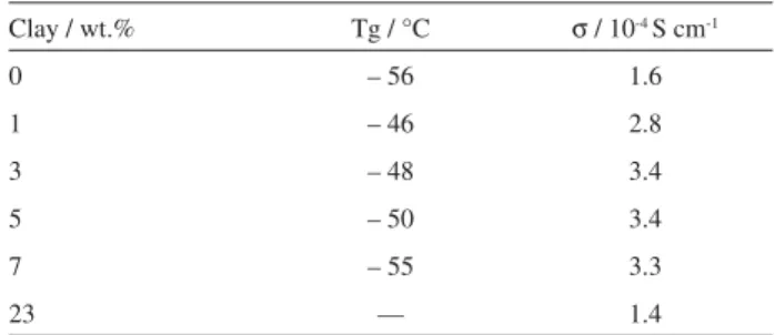
Table 1. Glass transition temperature (Tg) and ionic conductivity (S) for CPE prepared with different concentrations of clay
Clay / wt.% Tg / °C S / 10-4S cm-1
0 – 56 1.6
1 – 46 2.8
3 – 48 3.4
5 – 50 3.4
7 – 55 3.3
23 — 1.4
corresponding to an interlamellar distance of 1.77 nm. Comparing with the interlamellar distance for the modified MMT employed in this work, 1.97 nm, we can infer from these results that the both polymer and plasticizer are interacting with the clay, however, the clay is not exfoliated, but it keeps its lamellar structure instead. The decrease in the interlamellar distance can be explained by the removal of the quaternary ammonium salt employed to modify the clay by the polymer and the plasticizer. The appearance of a peak at 2Q = 3.3° is unclear and can be related to any crystallization induced by the presence of the clay.
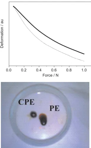
Figure 5 presents the thermomechanical characterization of the electrolytes based on P(EO-EPI), GBL, LiI and I2, with and without the addition of 5 wt.% of clay. According to this data, the presence of the MMT promotes an increase in the mechanical stability of the entire system. This can be viewed considering the force applied to the CPE film which promotes a lower deformation comparing to the film without any clay. The difference in the mechanical
properties is also illustrated as an inset in Figure 5 where a picture of spherical shaped samples of both the CPE and the plasticized polymer electrolyte prepared without clay are shown. In the case of the system without clay, there is a flow with time due to the action of gravity, leading to the disruption of the spherical shape. For the CPE, the spherical shape remains unchanged.
The results presented showed that the addition of MMT clay to the plasticized polymer electrolyte led not only to an increase in the ionic conductivity, but also to the solidification of the electrolyte, reflected as an improvement in mechanical stability of films.
Dye-sensitized solar cell characterization
Figure 6 shows the J-V characteristics of the solar cell assembled with the CPE containing 5 wt.% of MMT clay, under polychromatic irradiation at different illumination intensities. The parameters obtained from Figure 6 are summarized in Table 2.
Under irradiation of 100 mW cm-2, the DSSC presented
Jsc = 6.32 mA cm-2, V
occa.0.6 V and efficiency of ca.1.5%.
At 10 mW cm-2, the efficiency reaches 3.2 %, showing that
the efficiency increases when the intensity of irradiation is decreased. The mechanism of charge transport in these devices includes diffusion of ionic species in the electrolyte and inside the nanoporous TiO2. Under high light intensities a great number of charge carriers are generated (electrons injected from the excited dye to the conduction band of the TiO2 nanoparticles). This process occurs faster than the regeneration of the dye cation by the electrolyte. Such a difference in time scale is responsible for the increase in the recombination of the injected electrons, reducing
Figure 5. Thermomechanical analysis (compression mode) for electrolytes based on P(EO-EPI), GBL, LiI and I2: (dashed line) without clay and (solid line) with 5 wt.% of MMT clay. The inset shows a picture of spherical shaped samples of the polymer electrolyte prepared with 5 wt.% of MMT clay (CPE) and without the clay (PE), after some period of time at ambient conditions.
the short circuit current and the efficiency. At low light intensity however, the small number of charge carriers can be efficiently compensate by the ionic species in the electrolyte. This effect is more pronounced for polymer and gel electrolytes,42,43 but is also observed for cells assembled
with liquid electrolytes.44This phenomenon seems to be
intrinsic to the Gratzel’s solar cell, and is observed in most cases although with different magnitudes.
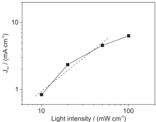
The cell investigated presented low fill factor values. This is probably related to a poor penetration of the CPE in the TiO2 film, causing a poor wettability and, therefore, favoring the recombination reactions inside the device. The loss in the photocurrent can also be observed in Figure 7, where a plot the JSC dependence on light intensity (IL) is shown. The JSC dependence of light intensity follows a power law JSCca. ILA. When the losses inside the device
are minimal, Aca.1, and JSC increases linearly with light
intensity. For the CPE investigated here, A ca.1 up to
50 mW cm-2(Figure 7). The last point, which corresponds to
the data collect under irradiation of 100 mW cm-2, is clearly
out of the linearity region. The deviation from linearity at high light intensity levels observed for the DSSC assembled with solid electrolytes is a consequence of the reduced ionic mobility in the polymer medium.
However, we observed previously that for a plasticized polymer electrolytes where the ionic mobility is quite high, the Jsc dependence on light intensity is almost linear even considering the current under irradiations higher than 50 mW cm-2 (A 0.9).4343 Considering this previous data,
and the value of ionic conductivity obtained for the CPE investigated in this work, the deviation form linearity at high irradiation levels is more likely due to a poor wettability of the TiO2/dye film. Phase segregation and/or formation of aggregates make the penetration of the CPE difficult. This effect also leads to very poor FF values and lower current densities. And, of course, this effect is more pronounced under 100 mW cm-2 where the density of photogenerated
electrons are too high to be compensated by the lack of CPE in certain regions of the film. As consequence, this
lack of CPE favors the recombination with the excited dye, reducing the collected current. Nevertheless, the efficiency obtained is close to that usually obtained for DSSC assembled with solid-state polymer electrolytes or organic or inorganic hole conductors. The results presented here are also very encouraging. Once the method of preparation of CPE can be further optimized in order to obtain a more exfoliated and homogenous mixture of the clay, polymer, and plasticizer, the DSSC efficiency will improve significantly.
Conclusions
CPE based on the copolymer P(EO-EPI), the plasticizer GBL and MMT clay were characterized and applied in a solid-state dye-sensitized solar cell. The clay added to the electrolyte enhanced both the ionic conductivity and the mechanical properties of the electrolyte. According to the thermal analyses, at small amount of clay, the inorganic additive is interacting more with the polymer phase, after 3% of clay, it seems that the additional clay is transferred to the plasticizer phase removing the clay from the polymer phase. This can explain the decrease in the Tg values and the plateau in the ionic conductivity plot (Sca. 3.4 mS cm-1)
between 3 and 7 wt.% of clay.
The solar cells devices presented efficiencies of 1.6% and 3.2% at 100 mW cm-2 and 10 mW cm-2, respectively.
This result is considered very promising as it is close to the values usually obtained for DSSC prepared with solid electrolytes. FF values are very poor; this can be due to the low penetration of the CPE inside the porous of the TiO2 film. However, the efficiency of the devices can be optimized in the future, by changing the method of assembling the CPE and optimizing the deposition
Table 2. Short circuit current (Jsc), open circuit potential (Voc), fill factor (FF) and efficiency (H) for a dye-sensitized solar cell assembled with CPE containing 5 wt.% of MMT clay, under polychromatic irradiation of different intensities
Intensity / mW cm-2 J
SC/ mA cm-2 VOC/ V FF/ % H/ %
100 6.3 0.60 39 1.5
50 4.6 0.57 40 2.3
20 2.4 0.52 47 3.2
10 0.8 0.49 53 3.2
technique during solar cell assembly. Despite the very promising characteristics that polymer-clay composites usually exhibit, there are only few works that attempt to the applications of these composites to optoelectronic or electrochemical devices. To our knowledge, this is the first report of a DSSC assembled with a composite electrolyte containing a MMT clay derivative.
Acknowledgments
The authors acknowledge FAPESP (fellowships 05/56924-0 and 05/56627-5), CNPq for financial support, Daiso Co. Ltd., Osaka, Japan and Bentec, Livorno, Italy for providing the copolymer and the MMT samples, respectively and finally to Dr. Ryan C. White for English revision.
References
1. O’ Reagan B.; Grätzel M.; Nature1991,353, 737-740. 2. Meng, Q. B.; Takahashi, K.; Zhang, X. T.; Sutano, I.; Rao, T. N.;
Sato, O.; Fujishima, A.; Watanabe, H.; Nakamori, T.; Langmuir
2003,19, 3572.
3. Kroeze, J. E.; Hirata, N.; Schmidt-Mende, L.; Orizu, C.; Ogier, S. D.; Carr, K.; Gratzel, M.; Durrant, J. R.; Adv. Funct. Mater.
2006,16, 1832.
4. Tan, S. X.; Zhai, J.; Xue, B. F.; Wan, M. X.; Meng, Q. B.; Li, Y. L.; Jiang, L.; Zhu, D. B.; Langmuir2004,20, 2934. 5. Wang, P.; Zakeeruddin, S. M.; Moser, J. E.; Grätzel, M.; J. Phys.
Chem. B2003,107, 13280.
6. Yamanaka, N.; Kawano, R.; Kubo, W.; Masaki, N.; Kitamura, T.; Wada, Y.; Watanabe, M.; Yanagida, S.; J. Phys. Chem. B
2007,111, 4763.
7. Kalaignan, G. P.; Kang, M. S.; Kang, Y. S.; Solid State Ionics
2006,177, 1091.
8. Kang, M. S.; Kim, J. H.; Won, J.; Kang, Y. S.; J. Photochem. Photobiol. A2006,183, 15.
9. Kim, Y. J.; Kim, J. H.; Kang, M. S.; Lee, M. J.; Won, J.; Lee, J. C.; Kang, Y. S.; Adv. Mater.2004,16, 1753.
10. Wang, P.; Zakeeruddin, S. M.; Grätzel, M.; J. Fluorine Chem.
2004,125, 1241.
11. Wang, P.; Zakeeruddin, S. M.; Moser, J. E.; Nazeeruddin, M. K.; Sekiguchi, T.; Grätzel, M.; Nat. Mater.2003,2, 402. 12. Kubo, W.; Murakoshi, K.; Kitamura, T.; Yoshida, S.; Haruki,
M.; Hanabusa, K.; Shirai, H.; Wada, Y.; Yanagida, S.; J. Phys. Chem. B2001,105, 12809.
13. Kato, T.; Okazaki, A.; Hayase, S.; J. Photochem. Photobiol. A
2006,179, 42.
14. Shibata, Y.; Kato, T.; Kado, T.; Shiratuchi, R.; Takashima, W.; Kaneto, K.; Hayase, S.; Chem. Commun.2003, 2730.
15. Nogueira, A. F.; Alonso-Vante, N.; De Paoli, M.-A.; Synth. Met.
1999,105, 23.
16. Nogueira, A. F.; Durrant, J. R.; De Paoli, M.-A.; Adv. Mater.
2001,13, 826.
17. Kumar, M.; Sekhon, S. S.; Eur. Polym. J.2002,38, 1297. 18. Nogueira, A. F.; Longo, C.; De Paoli, M.-A.; Coord. Chem Rev.
2004,248, 1455.
19. Nogueira, V. C.; Longo, C.; Nogueira, A. F.; Soto-Oviedo, M. A.; De Paoli, M.-A.; J. Photochem. Photobiol. A 2006,181, 226.
20. De Freitas, J. N.; Nogueira, V. C.; Ito, B. I.; Soto-Oviedo, M. A.; Longo, C.; De Paoli, M.-A.; Nogueira, A. F.; Int. J. Photoenergy
2006, Art. No. 75483.
21. Croce, F.; Appetecchi, G.; Persi, L.; Scrosati B.;Nature1998,
394, 456.
22. Stergiopoulos, T.; Arabatzis, I. M.; Katsaros, G.; Falaras, P.; Nano Lett. 2002,2, 1259.
23. Katsaros, G.; Stergiopoulos, T.; Arabatzis, I. M.; Papadokostaki, K. G.; Falaras, P.; J. Photochem. Photobiol. A2002, 149, 191.
24. Usui, H.; Matsi, H.; Tanabe, N.; Yanagida, S.; J. Photochem. Photobiol. A2004,164, 97.
25. Kato, T.; Kado, T.; Tanaka, S.; Okazaki, A.; Hayase, S.; J. Electrochem. Soc.2006,153, A626.
26. Kato, T.; Hayase, S.; J. Electrochem. Soc.2007,154, B117. 27. Singhal, R. G.; Capracotta, M. D.; Martin, J. D.; Khan S. A.,
Fedkiw, P. S.;J. Power Sources2004,128, 247.
28. Walls, H. J.; Riley, M. W.; Singhal, S. S.; Spontak, R. J.; Fedkiw, P. S.; Khan, S. A.; Adv. Funct. Mater.2003,13, 710.
29. Aranda P.; Ruiz-Hitzky, E.; Appl. Clay Sci.1999,15, 119. 30. Wang, P.; Zakeeruddin, S. M.; Comte, P.; Exnar, I.; Grätzel, M.;
J. Am. Chem. Soc.2003,125, 1166.
31. Stathatos, E.; Lianos, P.; Zakeeruddin, S. M.; Liska, P.; Grätzel, M.;Chem. Mater.2003,15, 1825.
32. Meneghetti, P.; Qutubuddin, S.; Webber, A.; Electrochim. Acta
2004,49, 4923.
33. Chen, H.- W.; Lin, T.- P.; Chang, F.- C.; Polymer2002,43, 5281.
34. Chen, H.-W.; Chang, F.-C.; Polymer2001,42, 9763. 35. Wang, P.; Zakkeruddin, S. M.; Grätzel, M.; J. Fluorine Chem.
2004,125, 1241.
36. Homminga, D.; Goderis, B.; Dolbnya, I.; Reynaers, H.; Groeninckx, G.; Polymer 2005,46, 11359.
37. Wang, M.; Zhao, F.; Guo, Z.; Dong, S.; Electrochim. Acta2004,
49, 3595-3602.
38. Nogueira, A. F.; Spinace, M. A. S.; Gazotti, W. A.; Girotto, E. M.; De Paoli, M.-A.; Solid State Ionics2001,140, 327. 39. Gazotti, W. A.; Spinace, M. A. S.; Girotto, E. M.; De Paoli,
M.-A.;Solid State Ionics2000,130, 281.
41. Gazotti, W. A.; Spinace, M. A. S.; Girotto, E. M.; De Paoli, M.-A.;Solid State Ionics2000,130, 281.
42. Nogueira, A. F.; Durrant, J. R.; De Paoli, M.-A.; Adv. Mater.,
2001,13, 826.
43. Freitas, J. N.; Longo, C.; De Paoli. M.-A.; Winnischofer, H.; Nogueira, A. F.; J. Photochem. Photobiol. A 2007, 189, 153.
44. Nazeruddin, M. K.; Kay, A.; Rodicio, I.; Humphry-Baker, R.; Grätzel, M.; J. Am. Chem. Soc.1993 , 115, 6382.
Received: October 1, 2007
Web Release Date: April 2, 2008