*e-mail: [email protected]
Fiberglass-reinforced Glulam Beams: Mechanical Properties
and Theoretical Model
Juliano Fiorellia*, Antonio Alves Diasb
a
São Paulo State University, UNESP, Rod. Com. João Ribeiro de Barros, Km 651,
17900-000 Dracena, São Paulo, Brazil
b
São Carlos School Engineering, USP, São Carlos, São Paulo, Brazil
Received: August 30, 2005; Revised: June 8, 2006
The glued-laminated lumber (glulam) technique is an eficient process for making rational use of wood. Fiber-Reinforced Polymers (FRPs) associated with glulam beams provide signiicant gains in terms of strength and stiffness, and also alter the mode of rupture of these structural elements. In this context, this paper presents a theoretical model for designing reinforced glulam beams. The model allows for the calculation of the bending moment, the hypothetical distribution of linear strains along the height of the beam, and considers the wood has a linear elastic fragile behavior in tension parallel to the ibers and bilinear in compression parallel to the ibers, initially elastic and subsequently inelastic, with a negative decline in the stress-strain diagram. The stiffness was calculated by the transformed section method. Twelve non-reinforced and iberglass reinforced glulam beams were evaluated experimentally to validate the proposed theoretical model. The results obtained indicate good congruence between the experimental and theoretical values.
Keywords: Glued-laminated lumber, FRP, strain
1. Introduction
When applied to structural elements, Glued-Laminated Lumber (Glulam) refers to the material produced by gluing together the tops and faces of wood chips, in lat or curved shape, with the ibers of all the sheets parallel to the axis of the piece. Long sheets are obtained by joining boards together longitudinally, gluing them face to face and edge to edge to obtain the desired height and width. The sheets can also be bent to produce a curved shape during gluing. All these factors allow for a wide variety of design choices, subject only to production and/or application cost restrictions.
The glulam technique is a rational option for adding value to lumber. The use of iberglass to reinforce beams ensures gains in the structural element’s strength and stiffness, and alters its mode of rupture, which becomes marked by considerable displacements after insertion of the FRPs.
This paper presents a theoretical model for designing FRP-rein-forced glulam beams. The proposed model admits the hypothesis of linear strains distributed along the height of the beam, and considers the wood has a linear elastic fragile behavior in stress applied parallel to the ibers and bilinear in compression parallel to the ibers.
To validate the numerical design model, tests were carried out on glulam beams made of Pinus caribaea var. Hondurensis species with and without FRP. The experimental results for the bending moment and lexural stiffness are congruent with the values determined by the theoretical model.
2. Literature Review
The idea of reinforcing glulam beams came in response to the need to improve the mechanical properties of strength and stiffness and to increase the reliability of this type of structural element.
Lindyberg1 stated that various design methods are used to analyze beams with and without reinforcement in bending. These methods
can be divided into empirical, deterministic and probabilistic. The ASTM D 3737/96 – Standard Test Method for Establishing Stresses for Structural Glue Laminated Lumber2 establishes empirical methods for the design of glulam beams, which take into account the lexural strength of defect-free test specimens and establish coeficients of modiication relating to the existing defects in these elements. The author concludes that reinforced glulam beams have a complex mode of rupture which makes it dificult to use empirical solutions.
Fiorelli and Dias3 presented a deterministic model to calculate the stiffness and strength of iber-reinforced solid lumber beams. The stiffness was based on the transformed section concept. To calculate the mode of rupture, the model considers rupture by compression of the upper ibers or rupture by straining of the lower ibers. To evalu-ate the ultimevalu-ate moment, the model considers the ultimevalu-ate tensile and compressive strength of the lumber. This model is based on the hypothesis of Navier/Bernoulli (plane sections remain plane after straining). A comparison of the experimental and theoretical results demonstrated very similar values of strength and stiffness.
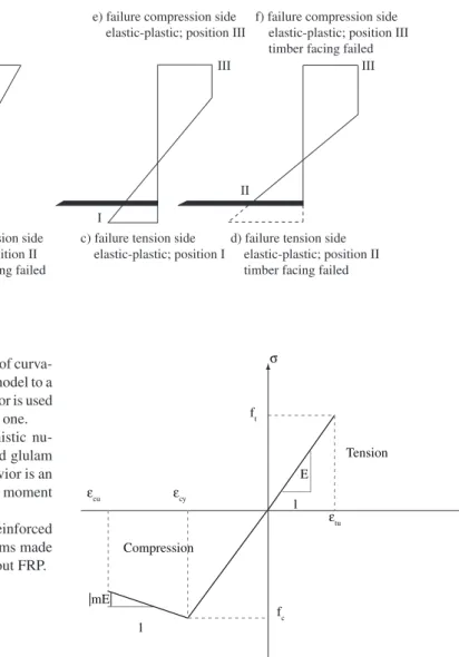
Romani and Blab4 presented a design model for iber-reinforced glulam beams. In this work, the authors showed different rupture moduli for the reinforced glulam beam (Figure 1).
The authors experimentally tested 10 x 30 cm glulam beams rein-forced with carbon and aramid ibers, comparing their experimental results of the moment of rupture with their theoretical results. The authors stated that the proposed calculation model was quite con-servative, showing a difference of approximately 35% below that of the experimental results.
of the reinforced beam. This model is based on the moment of curva-ture (M-φ). The second part incorporates the deterministic model to a probabilistic model. The Monte Carlo computational simulator is used to develop the probabilistic model within the deterministic one.
From that standpoint, the development of a deterministic nu-merical model to determine the strength of iber-reinforced glulam beams based on the lumber’s compressive and tensile behavior is an adequate procedure to determine the value of the bending moment of iber-reinforced glulam beams.
This paper presents a theoretical model to evaluate reinforced glulam beams and an experimental analysis of lumber beams made of Pinus caribaea var. Hondurensis species with and without FRP.
3. Theoretical Model
3.1. Moment of rupture
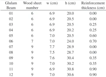
The theoretical deterministic calculation model proposed here considers the behavior of the stressed lumber and ibers realistically. The lumber subjected to compressive loads parallel to the ibers exhibits an initially linear elastic behavior, reaching compressive strength parallel to the ibers (fc), followed by decreasing levels of stress as the strains increase, until the material breaks up5. The lumber subjected to tensile forces parallel to the ibers displays a linear elastic behavior until it approaches the moment of rupture.
Figure 2 depicts the behavior admitted for the material in the calculation model: a linear elastic fragile behavior of the lumber in strains parallel to the ibers and bilinear in compression parallel to the ibers (initially elastic and subsequently inelastic, with a negative decline in the stress-strain diagram).
The value of strain at the level of stress corresponding to the ten-sile strength and in compression (ft0 and fc0, respectively) is obtained from these values and from the modulus of elasticity (E), according to Equation 1.
E f E f cy 0 0 tu t c
f = f = (1)
To calculate the bending moment, after determining the position of the neutral line (N.L.), it is possible to evaluate the loads acting on each sheet of lumber in the transversal section of the glulam beam and in the layer of iberglass.
With regard to the tensile rupture mode, one considers that failure is reached when the maximum strain acting on the lumber reaches the tensile strength (ft).
As for the compressive rupture mode, after the strain at the compressed edge reaches the value of fc, the section undergoes gradual plasticization, lowering the neutral line. The lexural strength increases until it reaches a maximum, after which it decreases. The ultimate state for compression is considered at the point where the lexural strength reaches it maximum value.
3.2. Flexural stiffness
The lexural stiffness was analyzed by the transformed section method (Equation 2).
12
EI E b h E b h di
3 2 i i i $ $ $ + $ $ R
= d n (2)
where:
Ei – Modulus of elasticity in sheet i; hi – Height of sheet i;
b – Width of the beam;
di – distance from the Center of Gravity (C.G.) of the sheet to the beam’s C.G.
e) failure compression side elastic-plastic; position III
f) failure compression side elastic-plastic; position III timber facing failed
I I
II II
III III
b) failure tension side elastic; position II timber facing failed
d) failure tension side elastic-plastic; position II timber facing failed a) failure tension side
elastic; position I
c) failure tension side elastic-plastic; position I
Figure 1. Rupture modes of glulam beams.
E S
Tension
Compression
ft
Ecu Ecy
Etu fc |mE| E 1 1
4. Materials and Methods
To evaluate the strength and stiffness of the FRP reinforced glu-lam beams, twelve prototypes were prepared using Pinus caribaea var. hondurensis lumber. The glulam beams were reinforced with iberglass along the last line of glue of the tensioned section. The percentage of iber employed was equal to 1.2% and 3.3% of the height of the beam. The wood was glued with Phenol-resorcinol (Axo-Nobel) adhesive and the unidirectional iberglass fabric (UF 0900, FIBERTEX) was glued with AR-300 epoxy adhesive. Four beams were not reinforced. The beams had a nominal section of (7 x 20 x 400 cm) and (7 x 30 x 400 cm) and sheets with a thickness of about 3.3 cm. The size, number of sheets, and thickness of the reinforce-ment of the glulam beams evaluated experireinforce-mentally are described in Table 1.
4.1. Classification of the sheets
The lumber sheets used for preparing the glulam beams were classiied mechanically through static tests. A visual classiication was also done following the procedures established by Carreira6. The modulus of elasticity values determined here were used in the theoretical model to evaluate the beam’s strength and stiffness.
4.2. Characterization of the fiberglass fabric
The mechanical properties of strength and stiffness (Table 2) of the iberglass fabrics were determined by means of mechanical tests, following the recommendations of the ASTM D 3039-95 – Standard Test Method for Tensile Properties of Polymer Matrix Composite Materials, of the American Society for Testing and Materials7.
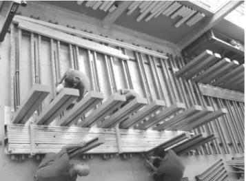
4.3. Glulam beam fabrication method
Fabrication of glulam beams must be preceded by visual and mechanical classiication of the sheets. The fabrication procedure is divided in two steps; the irst consists of applying the adhesive and gluing the sheets together and the second involves applying the
iberglass reinforcement. Figure 3 illustrates the reinforced glulam beam fabrication procedure.
4.4. Instrumentation of the beams
The beams were instrumented with KFG-10-20-120-C1-11 Kyowa extensometers ixed to the mid-span section of the upper and lower faces and at half height on the lateral faces of the next to last sheet, adjacent to the reinforcement (Figure 4). The purpose of this procedure was to evaluate the variation in strain in the beam’s cross-sections.
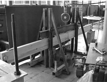
4.5. Bending test of glulam beams
The beams were subjected to a bending test with loads applied at one-third intervals along the span, following the recommenda-tions of the ASTM D198-97-Standard Test Methods of Static Tests of Lumber in Structural Sizes, of the American Society for Testing and Materials8.
A static design of simply supported beam was adopted for the tests, with the application of equal loads at one-third intervals of the span (Figure 5). The values of the displacements were measure in central region of the beam with dial indicator. The velocity of load application was of 10 MPa per minute, in normal stress maximum.
5. Results
5.1. Fiber characterization tests
Table 2 lists the mechanical properties of the ibers used in the experimental work.
5.2. Bending tests
The results of the bending moment and lexural stiffness (EI) of the beams are given in Table 3.
Two values are presented for the bending moment of the rein-forced glulam beams, corresponding to:
• M1 – value of the bending moment when rupture occurred in the last strained sheet, positioned below the reinforcement; and • M2 – value of the bending moment when inal rupture of the
beam occurred.
5.3. Timber characterization tests
Test specimens were removed from the evaluated beams to char-acterize the lumber. Table 4 shows the values of compressive strength parallel to the ibers (fc0) and of strain parallel to the ibers (ft0).
6. Analysis of the Results
6.1. Analysis of flexural stiffness
Table 5 compares the results of the experimental (EIexp.) and theoretical (EIteo.) lexural stiffness (EI).
The analysis of the stiffness of the beams with and without iber-glass reinforcement compares values obtained from experimental tests against theoretical values determined according to the transformed section model. As can be seen, the experimental results generally show good congruence with the theoretically estimated lexural stiffness.
6.2. Strain analysis
The strain values are shown graphically (Figure 6 and 7), with experimental and theoretical values of the strain variations along the height, for different loads and six evaluated beams.
In Figures 6 and 7, the experimental strains are marked by dots, with a dashed line connecting the dots corresponding to a given
load-Table 1. Information of glulam beams.
Glulam Beam
Wood sheet number
w (cm) h (cm) Reinforcement thickness (cm)
01 6 6.9 20.0 0.00
02 6 6.9 20.5 0.00
03 6 6.9 20.5 0.25
04 6 6.9 20.2 0.25
05 6 7.0 20.5 0.60
06 7 7.0 24.0 0.70
07 9 7.7 28.9 0.00
08 9 7.5 28.7 0.00
09 9 7.6 30.4 0.35
10 9 7.0 30.2 0.35
11 9 6.9 30.8 0.90
12 9 7.0 30.6 0.90
Table 2. Strength and Stiffness values.
Strength Stiffness
Mean (MPa) 1247 56154
Application of glue on sheets. Pressing of the beam.
Application of iberglass fabric. Pressing of beam with reinforcement.
Control of pressure using torquemeter. Detail of the reinforced beam.
ing value. The continuous lines represent the strain values obtained theoretically. In each igure, dashed and continuous lines of the same color correspond to the same loading level.
The last continuous line represents theoretical strains calculated for the value of the experimental moment at the irst rupture, for which it was not possible to evaluate the strains experimentally.
An analysis of Figure 6 and 7 indicates that the theoretical strains are very close to the experimental strains, except for beam 12. The difference between experimental and theoretical strains in beam 12 may have occurred because this beam had a larger number of sheets (greater height and higher percentage of reinforcement) and hence, the existence of a shear strain of the adhesive, an effect the theoretical model does not take into account. The non-reinforced beams 2 and 8 presented a slight difference between experimental and theoretical strains.
6.3. Analysis of the bending moment
To evaluate the theoretical bending moment using the numeri-cal model, the mechaninumeri-cal properties of strength and elasticity of the lumber and the iberglass were considered. The tensile strength parallel to the ibers was calculated using the tensile strength values of defect-free CP (ft0) (Table 4) multiplied by the coeficient 0.64, to consider the transposition to the structural element and the existence
Figure 5. Bending test.
Table 3. Experimental values of failure moment and bending stiffness.
Beam Section (cm) EI (kN.cm2) Failure moment (kN.cm)
M1 M2
01 6.9 20.0 6,488,396 2489
-02 6.9 20.5 6,914,197 2273
-03 6.9 20.5 6,644,274 2381 2814
04 6.9 20.2 6,766,187 2056 2887
05 7.0 20.5 7,022,504 2561 3283
06 7.0 24.0 9,980,947 3210 3694
07 7.7 28.9 16,826,463 3824
-08 7.5 28.7 17,179,260 4220
-09 7.6 30.4 22,050,998 6200 7835
10 7.0 30.2 19,278,948 6143 6875
11 6.9 30.8 24,255,268 8173 8906
12 7.0 30.6 21,978,306 7948 8568
Table 4. Strength mean values.
Beam Strength (MPa)
fc0 ft0
01 52.3 89.2
02 51.4 70.4
03 49.2 67.3
04 51.1 65.3
05 50.5 62.1
06 51.3 70.2
07 44.4 66.2
08 47.2 58.5
09 54.6 78.1
10 51.4 90.0
11 61.3 76.3
12 54.0 98.2
Table 5. Flexural stiffness (experimental and theoretical results).
Beam EIexp.kN.cm2 EI teo.kN.cm
2 EI
exp./EI teo.
1 6,488,396 6,864,927 0.94
2 6,914,197 6,882,334 1.01
3 6,644,274 7,402,057 0.90
4 6,766,187 6,711,977 1.01
5 7,022,504 6,972,873 1.01
6 9,980,947 10,245,491 0.97
7 16,826,463 18,179,793 0.93
8 17,179,260 17,458,861 0.98
9 22,050,998 20,186,708 1.09
10 19,278,948 20,080,207 0.96
11 24,386,700 23,300,058 1.04
12 21,601,543 22,844,327 0.94
Fibra de vidro E1
E1
E2 E3 E2 E3
E4 E4
Fibra de vidro
of joins in the sheets9. The values of the bending moment correspond to the irst rupture (M1).
Table 6 indicates that the value of the theoretical bending moment correlates well with the experimental values, showing, on average, a maximum variation of 18% below the value of the experimental bending moment.
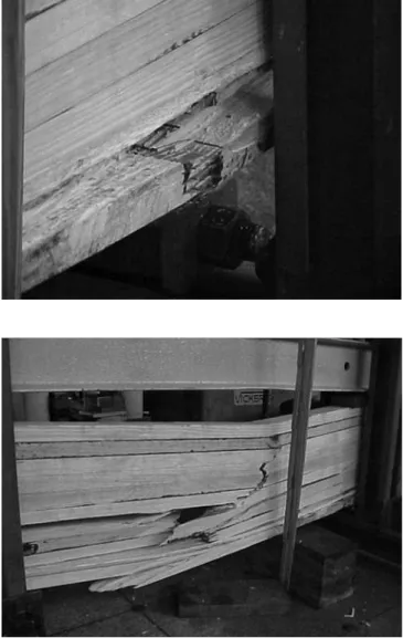
6.4. Analysis of rupture
The experimentally evaluated reinforced glulam beams presented two modes of rupture. The irst occurred by strain on the sheet posi-tioned under the reinforcement layer, while the second consisted of a combination of compressive tensile rupture and shear (Figure 8).
7. Conclusions
The proposed calculation model shows a good correlation be-tween the experimental and theoretical results for the tested beams. In the evaluation of lexural stiffness EI (transformed section method), the values showed a difference of about 5%. A good correlation was obtained between the experimental and theoretical values for the bending moment.
An analysis of the strains of the experimentally tested beams al-lows us to state that, in most of the beams evaluated here, the
theoreti-cal strains determined by the proposed theoreti-calculation model were close to the experimental strains, conirming the validity of the hypotheses adopted. In view of the results obtained for the higher beam containing
Table 6. Failure moment (experimental and theoretical values).
Beam fc0 CP ft0 Mexp. (kN.cm)
Mteo (kN.cm)
Mexp./Mteo
1 52.3 57.1 2489 2449 1.01
2 51.4 45.1 2273 2065 1.10
3 49.2 43.1 2381 2139 1.11
4 51.1 41.8 2056 2014 1.02
5 50.5 39.7 2561 2165 1.18
6 51.3 44.9 3210 3269 0.98
7 44.4 42.4 3824 3888 0.98
8 47.2 37.5 4220 3655 1.15
9 54.6 50.0 6200 5249 1.18
10 51.4 57.6 6143 6161 0.99
11 61.3 48.8 8173 6291 1.29
12 54.0 62.8 7948 7280 1.09
Figure 6. Variation of the strain in the cross-section: a) beam 02; b) beam 04;
and c) beam 05. Section: 7 x 20 cm.
0 4 8 12 16 20 24 28
- 7 - 6 - 5 - 4 - 3 - 2 - 1 0 1 2 3 4 5 6 7 Milhares
0 4 8 12 16 20
- 5 - 4 - 3 - 2 - 1 0 1 2 3 4 5
Milhares
(a) (a)
Figure 7c. Variation of the strain in the cross-section: a) beam 08; b) beam
10; and c) beam 12. Section: 7 x 30 cm.
0 4 8 12 16 20 24 28
- 7 - 6 - 5 - 4 - 3 - 2 - 1 0 1 2 3 4 5 6 7 Milhares
0 4 8 12 16 20
- 5 - 4 - 3 - 2 - 1 0 1 2 3 4 5
Milhares
(b) (b)
0 4 8 12 16 20 24 28
- 7 - 6 - 5 - 4 - 3 - 2 - 1 0 1 2 3 4 5 6 7 Milhares
0 4 8 12 16 20
- 5 - 4 - 3 - 2 - 1 0 1 2 3 4 5
Milhares
Figure 8. Rupture modes of the experimentally evaluated glulam beams.
a greater percentage of reinforcement, it can be inferred that better results could be obtained by incorporating into the theoretical model the shear strain of the adhesive in the reinforcement layer.
Two modes of rupture were observed, the irst by strain in the sheet positioned under the reinforcement layer and the second caused by a combination of compressive tensile rupture and shear.
Acknowledgments
The authors gratefully acknowledge the inancial support of the Brazilian research inancing institution FAPESP – Fundação de Amparo a Pesquisa do Estado de São Paulo and FIBERTEX that provided the glass ibers.
References
1. Lindyberg RF. ReLAM: A nonlinear, probabilistic model for the analysis
of reinforced glulam beans in bending. [Unpublished D. Phil thesis]. Maine: University of Maine; 2000.
2. American Society for Testing and Materials. ASTM D3737. 1996,
Standard Test Method for Establishing Stresses for Structural Glue Laminated Timber (Glulam).
3. Fiorelli J, Dias AA. Analysis of the strength and stiffness of timber beams
reinforced with carbon iber and glass iber. Materials Research. 2003;
6(2):193-202.
4. Romani M, Blab H J. Design model for FRP Reinforced Glulam Beams.
Proceedings of the International Council Forresearch and Innovation in Building and Construction; 2001, Venice, Italy.
5. Buchanan AH. Bending Strength of Lumber. Journal of Structural
En-gineering, ASCE. 1990; 116(5):1213-1229.
6. Carreira MR. Critérios para classificação visual de peças estruturais de
Pinus ssp. [Dissertation]. São Carlos: University of São Paulo, 2003.
7. American Society for Testing and Materials. ASTM D3039. 1995,
Stand-ard Test Method for Tension Properties of Polymer Matrix Composite Materials.
8. American Society for Testing and Materials. ASTM D198. 1997, Standard
Test Methods of Static Tests of Lumber in Structural Sizes.
9. Fiorelli J. Estudo teórico e experimental de vigas de Madeira Laminada