Study of texture and microstructure evaluation of steel API 5L X70
under various thermomechanical cycles
Mohammad Masoumi
n, Luis Flavio Gaspar Herculano, Hamilton Ferreira Gomes de Abreu
Department of Metallurgical and Materials Engineering, Universidade Federal do Ceará, Fortaleza, CE, Brazila r t i c l e
i n f o
Article history: Received 9 March 2015 Received in revised form 6 May 2015
Accepted 10 May 2015 Available online 19 May 2015
Keywords:
Crystallographic texture Thermomechanical path EBSD
a b s t r a c t
This work studies the influence of different thermomechanical paths on the microstructure and crystallographic texture across the thickness of API 5L X70 pipeline steel manufactured via hot rolling using X-ray diffraction (XRD), scanning electron microscope (SEM), and electron backscattered diffrac-tion (EBSD). The starting materials were controlled hot-rolled at 10001C to 44% and 67% reductions and subsequently heat treated with such processes as annealing, water quenching and quench tempering at three different temperatures to evaluate the microstructure and crystallographic texture changes across the thickness. The banded ferrite-pearlite microstructure of the initial material was changed to acicular ferrite, quasi-polygonal ferrite, granular bainite, martensite and retained austenite via different heat treatments. Moreover, different thermomechanical paths induced crystallographic texture variations across the thickness, e.g., {112}//ND, {111}//ND1(
γ
fibre), and {011}//NDfibres dominated on the surfaceplane in contact with the rolls, whereas {001}//ND and particularly the (001)[1 1 0] texture component developed in the centre plane on which shear deformation has a zero value in this region. In this study, a simple interpretation of texture evolution was analyzed by comparison with the orientation changes that occurred during different rolling schedules and post-treatment processes.
&2015 Elsevier B.V. All rights reserved.
1. Introduction
Because pipeline steels are widely used for transportation of oil and natural gas over long distances, the demand for these materials has increased significantly in recent years. The mechanical properties of steels have been improved through control of microstructure and hardness, reductions in inclusion morphology, and use of low segregated uniform microstructures[1]. In this study, control of the crystallographic texture through-thickness was proposed to improve the mechanical properties. Recent results have shown that at the grain scale, crystallographic texture and grain–boundary distribution can play significant roles in defining the physical and mechanical properties of pipeline steels. These studies helped to postulate (though not to corroborate) that the resistance of low-carbon steels to the severe environments of pipeline service could be improved by controlling their crystallographic textures and grain–boundary dis-tributions[2]. Therefore, the current research studies the develop-ment of crystallographic texture during hot rolling and subsequent dynamic re-crystallisation.
The study of crystallographic texture in high-strength low-alloy steels (HSLA) is highly important for better understanding of a diversity of metallurgical mechanisms and mechanical properties. To this end, the texture changes are related to the active slip systems, the crystallography modifications during the
γ
-α
phasetransformation mechanisms [3], and the general mechanical anisotropy of the textured material. Our specific interest in the evolution of texture in the current API X70 material emphases the aspect of texture inhomogeneity across the thickness. Deformation induced via thickness texture inhomogeneity is a common phe-nomenon in hot- and warm-rolled materials[4,5].
During casting, the surface is solidified at an earlier stage, and alloy elements are rejected into the centre of the thickness. Therefore, the centre segregation zone develops as a result of a non-uniform distribution of elements through the cross-section. This segregation zone has a higher hardness than that of other regions. Matsumoto et al. [6] studied crack initiation suscept-ibility in high-strength pipeline steel and showed that the hard-ness of the segregation zone in a steel plate is a determining factor in increasing crack formation. Szpunar et al. [7] investi-gated hydrogen embrittlement (HE) in pipeline steel and found that the effect of the centre segregation zone on HE susceptibility can be removed by applying thermo-mechanical control proces-sing (TMCP).
Contents lists available atScienceDirect
journal homepage:www.elsevier.com/locate/msea
Materials Science & Engineering A
http://dx.doi.org/10.1016/j.msea.2015.05.020 0921-5093/&2015 Elsevier B.V. All rights reserved.
n
Corresponding author. Tel.:þ55 8589351001; fax:þ55 8533669969. E-mail address:[email protected](M. Masoumi).
It is well known that anisotropy can play a significant role in formability and mechanical properties of materials. Therefore, much attention has been focused on control of anisotropy to improve products. Crystallographic orientation is one of the controlling factors of anisotropy. Experimentation and modelling have increased our knowledge of texture evolution during defor-mation and post-treatment and assisted in identifying process variations that can improve product performance. In most ana-lyses of the textures developed via rolling, it is generally believed that plane strain conditions are applied during rolling[8]. Asbeck and Mecking[3]showed that texture inhomogeneity results from non-uniform shear deformation that occurs during rolling, whereas surface texture is caused by the surface roughness of the rolls. This shear deformation has a zero value in the centre plane but reaches a maximum value at the surface. A high value of hardness at the surface results from work hardening caused by additional shear strain due to friction between the rolls and sheet. It was found that a large amount of additional shear strain is applied to the surface of a cold-rolled sheet due to friction between the rollers and sheet surface if rolling is performed without lubrication[9]. The remaining shear stress causes textural and micro-structural inhomogeneity along the thickness direction. The texture heterogeneity becomes more pronounced under con-ditions of high friction. The surface shear textures developed in bcc metals include {001}o1104 and {111}o1104 components [10]. However, through-thickness variations in texture are also influenced by the properties of the material.
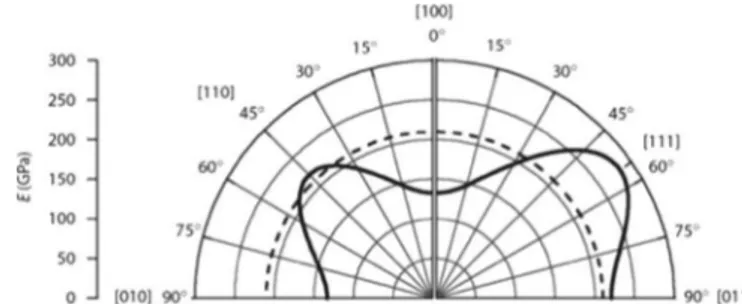
In bcc materials, slip occurs in the close-packed o1114 directions, but the slip plane could be any of the {110}, {112} or {123} planes; each of these planes contains the close-packed slip direction o1114. The choice of slip plane is influenced by the deformation temperature. At temperatures below Tm/4 (Kelvin temperature), {112} slip occurs; between Tm/4 and Tm/2, {110} slip is preferred; and at temperatures above Tm/2, {123} is favoured. At room temperature, iron slips on all three planes in a commono1114 direction, and the term“pencil glide”is used to describe the nature of the slip process in this case. One conse-quence of such slip is the wavy nature of the slip lines observed on the pre-polished surfaces of deformed specimens.Fig. 1shows the elastic modulus of iron single crystals as a function of crystal direction. Clearly, the elastic properties strongly differ from the well-known bulk modulus of 210 GPa (dotted line), which is only obtained in an isotropic, i.e., texture-free, material[11].
Post-treatments are defined as controlled heating and cooling of the materials to obtain a favoured microstructure and desired properties. Low carbon and alloy steels are the most widely used materials in the oil and gas industries, and the wide range of properties that can be obtained through various heat treatments is one of the main reasons for their widespread use. Changes in the crystallographic orientation distributions, microstructure, and mechanical properties during post-treatments can be obtained in the end product provided that the size of the part does not exceed
the hardenability limits of the alloy. The most common methods of heat treatment imposed on carbon and low-alloy steels are austeni-tising, quenching and tempering, normalising, austeniausteni-tising, quench-ing, and tempering. This transformation hardening process is generally referred to as the quenching and tempering process. This paper presents the effects of hot deformation and various post-treatments on the microstructural and textural changes across the material thickness. Samples of API X70 pipeline steel [12] were produced using different thermo-mechanical processes, including austenisation, controlled hot rolling, re-crystallisation and quench tempering, and are studied across the thickness using XRD, SEM and EBSD techniques. The studied specimens demonstrate similar micro-structures with various crystallographic textures and grain–boundary distributions through the thickness. These results support the hypothesis of improved mechanical properties and crystallographic texture through controlled hot rolling with post-heat-treatment, thus reducing the susceptibility of pipeline steels to hydrogen damage.
2. Experimental procedure
The starting material was a piece of API 5L x70 with an 8.5 mm thickness. The chemical composition is specified in Table 1. The starting samples were solution heat treated at 1473K (12001C) for 1 h to homogenise the sample and remove microsegregations. Energy-dispersive X-ray spectrometry (EDX) was performed to confirm that undesirable inclusions such as MnS were completely removed during homogenisation heat treatment followed by controlled hot rolling at 10001C to 5 mm and 3 mm in three and four passes, respectively, in a laboratory mill. After hot rolling, one portion of the strips was cooled in air to room temperature, and the other portion was quenched in water. Finally, tempering processes were performed at 6001C, 6501C and 7001C. Hardness measurements and SEM observations were used to ensure complete re-crystallisation with no substantial grain growth. The specimens produced by mentioned procedure has shown the different microstructures and crystallographic textures that analyzed subsequently.
For microstructural analysis, the cross-sections (RD-ND) of all specimens were ground with 120-grit, 220-grit, 400-grit, 600-grit, and 1200-grit SiC papers and polished with 6mm, 3mm and 1mm diamond paste suspensions, respectively. Next, samples were etched with a 2% Nital solution to determine the microstructure using scanning electron microscopic.
Macro-texture measurements were collected at different layers along the RD–TD sections to study the inhomogeneity of texture across the thickness at the surface and the one-quarter and centre layers. Three incomplete polefigures, i.e., {110}, {200}, and {211}, were measured using a Co goniometer. The ODF of each sample was determined from the measured polefigures using the M-text software. Bunge's Euler angles were adopted to describe the orientations, and the
φ
2¼451section of Euler space was used to display the computed ODFs.The EBSD analyses were conducted specifically on the surface and centre layers to collect micro-texture and meso-texture data from the test samples on the transverse (RD-ND) plane. Grain boundary distributions were defined in the EBSD-derived microstructures by the presence of a point-to-point misorientations greater than 31.
3. Results and Discussion
3.1. Metallographic Inspection
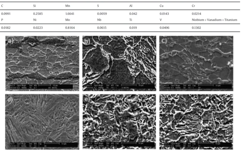
Fig. 2shows typical SEM images taken from the RD-ND cross-sections of specimens after hot deformation and post-treatments. The API steels are categorised as an HSLA steel type that can obtain
various microstructures and mechanical properties via different heat treatments. The starting X70 material possesses a banded ferritic-pearlitic microstructure (Fig. 2a) with quasi-polygonal ferrite due to the formation process. This morphology indicates that partial re-crystallisation took place during the hot rolling process. The hardness and ferrite grains size were measured and illustrated at 16575 HV and 871
μ
m, respectively. Selected previous studies explained that certain inclusions such as MnS in the microstructure provide preferred sites for crack formation and facilitate paths for crack propagation [13]. With respect to the possible influence of MnS inclusions on the results of the study, two important aspects should be considered. First, the distribution of MnS inclusions is the same for all sets of specimens produced by the thermomechanical processes and post-treatments followed by austenisation. Second, these processes are not expected to notice-ably change the shape, amount, or distribution of MnS inclusions because of the relatively mild combinations of deformation degree and temperature involved. Therefore, the influence of MnS inclu-sions on the observed damage susceptibility by a group of samples is assumed to be the same in all groups and takes place during crack nucleation[1]. To eliminate the MnS inclusions, heat solu-tion treatment at 12001C for 1 hour was performed. Austenisation above the Tnr (non-recrystallisation) temperature followed by air-cooling developed the upper bainite and acicular ferrite and martensite austenite islands (M/A islands) (Fig. 2b). Bainite sheaves were nucleated at the prior austenitic grain boundaries and surrounded by iron carbide particles. The ferrite plates in the bainitic microstructure are nucleated at the austenitic grain boundaries and form packets consisting of parallel plates with similar crystallographic orientations [1]. Moreover, inmedium-and low-carbon steels [3,4], the acicular ferrite formation is associated with a beneficial mixture of strength and toughness properties. The achieved toughness values of the acicular ferrite microstructure could be related to the increased density of the high-angle grain boundaries (HAGBs) found among primary ferrite plates with high dislocation density. Because the boundaries act as strong obstacles to propagation of cleavage cracks, they force these cracks to change the microscopic propagation planes to accom-modate the new local crystallography [14]. It is difficult to determine the grain size of these structures, but the average grain size and hardness were estimated as 1371
μ
m and 19575 HV, respectively. During austenisation heat treatment, the grain size showed a gradual increase over that of the starting samples, from 8mm to 13mm. This phenomenon was expected due to annealing temperature and time in the furnace. In pipeline steels, austenite first transforms into polygonal ferrite during continuous cooling, and carbon concentrates in the remaining austenite. At lower temperatures, this transformation becomes more difficult until the retained austenite transforms into acicular ferrite. Thus, the retained austenite is stabilised by an enriched carbon zone. Because this transformation can take place satisfactorily at tem-peratures greater than 5001C, the carbon content in the remaining austenite can be quite high. Next, during the cooling, the remain-ing austenite with high-carbon content transforms into granular discrete island constituents that are martensite lath-like when the temperature reaches the martensitic transformation point[15].After deformation, the microstructure consisted of polygonal ferrite and quasi-polygonal ferrite grains (Fig. 2c) as a result of full re-crystallisation at a higher temperature range (49001C), and the increase in hardness from 165 HV to 190 HV has been
Table 1
Chemical analysis (emission spectrometry) of API X70 (in wt%).
C Si Mn S Al Cu Cr
0.0991 0.2585 1.6641 0.0059 0.042 0.0143 0.0214
P Ni Mo Nb Ti V NiobiumþVanadiumþTitanium
0.0182 0.0223 0.8164 0.0615 0.019 0.0496 0.1302
associated with ferrite grain refinement. Hu Anmin[16]reported that for a multi-pass hot deformation path at a temperature range from 11001C to 5501C, grain refinement mechanisms include re-crystallisation of austenite and ferrite, either simultaneously or interactively. At the same time, deformation-enhanced re-crystal-lisation takes place more easily by decreasing the driving force of re-crystallisation nucleation.
Water quenching following hot rolling produced a material that was essentially composed of low-carbon lath martensite and small amounts of retained austenite. The martensite laths were detected at several microns (Fig. 2d). The laths were normally separated by low-angle grain boundaries (LAGBs) and were highly distorted. Water quenching generates a large number of dislocations in the grain interiors, and dislocations become trapped at the sub-boundaries. Piled-up dislocations at the sub-boundaries change the sub-boundaries into LAGBs with higher stored energy. As a result, the hardness was increased significantly to 34875 HV. Moreover, a notably small amount of retained austenite was observed between the martensite laths. Thus, the carbon content at the grains decreases, and thus, the tetragonality of the lath martensite declines. The crystal structure of the lath martensite with carbon content below 0.2% is essentially body-centred cubic (bcc). Speich et al.[17]has reported that in low-carbon steel (co 0.2%), carbon diffusion in martensite during quenching is sufficient to form segregation of dislocations and lath boundaries. This carbon motion is attributed to the only slightly destroyed bcc structure. In other words, tetragonality distortion induced by solute atoms at octahedral sites could be ignored in the bcc lattice. E. Anelli and D. Colleluor[18]declared that for linepipes of X65 and X70 grades, the tempering temperatures should be greater than 6001C to produce the best toughness levels suitable for satisfying the specifications requirements, especially after strain aging. At temperatures above 6001C, the lath structure is partially recovered, dislocation annihilation can take place, and moderate dislocation density can result. In addition, re-crystallisation of ferrite begins in certain areas. New strain-free re-crystallised austenite grains can develop at aging temperatures of approxi-mately 6401C. The AC1 temperature for the steel is approximately 6431C, which is in good agreement with previous reports[19]. The new austenite was formed within the prior-tempered-martensite, which is characterised as HAGBs; therefore, these locations are known as preferred sites for heterogeneous nucleation. The growth of this new austenite occurs both perpendicular and parallel to the grain boundaries. Misorientation between adjacent grains provides a driving force for grain growth. At low aging temperature (approximately 4501C), the steels still exhibited a lath martensite structure with a high dislocation density similar to that of the water quenched condition because long-range disloca-tion migradisloca-tion cannot take place. The Nb(C, N) precipitates are revealed due to carbon extraction models at this temperature. Additionally, these Nb(C, N) particles could be formed during hot deformation and post-treatment. During aging at 5001C, recovery occurs at the earlier stages, and an apparently fully recovered microstructure is observed in high SFE metals such as iron. The volume fraction of the new austenite was shown to increase significantly if the steel was aged for 1 h above 6501C. The new austenite transformed predominantly into highly dislocated lath martensite and retained new austenite upon cooling from higher aging temperatures. At an aging temperature of 6501C, nucleation of a new phase was observed at certain of the prior lath boundaries (Fig. 2e and f). Finally, the new set austenite was transformed due to the softer bainitic structures that followed water quenching. After tempering at 7001C, the microstructure of X70 contains bainitic ferrite and granular bainite, and the M/A constituents on the grain boundaries are fully decomposed. Bainite lath merges to form wide laths, and thus, the original austenite
grain boundary is not clear. Therefore, the boundaries of the laths become vague. The M/A island constituent between the original laths is broken down and refined, leading the existence in the interior of wide laths. The sub-structure of granular bainite vanishes, and the M/A islands turn into tiny and spotty particles because of gradual collapse. The microstructure primarily consists of intergranular ferrite with bainite. It is clear that intragranular ferrite and partedfine lath bainite have high strength and good toughness. The transformation behaviour of this newly formed austenite is highly important because it appears to have a solid and direct influence on thefinal properties. In the initial stages of its development during aging, austenite becomes rich in carbon, which makes the austenite highly stable even if the steel is air cooled to room temperature. The austenite in this condition is free of dislocations, and a precipitate-free zone is observed surround-ing it[15]. In conclusion, as the aging temperature increases, the amount of alloying elements in solution in the new austenite also increases. This process acts to lower the Ac1 and leads to the formation of new austenite at lower aging temperatures. Thus, austenite begins to form in matrix structures of higher strength levels.
In general, hardness is taken as a measure of resistance against deformation. Thus, all strengthening mechanisms apparently decrease the dislocation movement and increase the stress required to move the dislocations through the material. The investigated specimens in the water-quenched condition demon-strate much of their strength due to carbon in solution in martensite and the high dislocation density in the laths of the alloyed martensite. Moreover, alloying elements that are present as substitutional atoms provide fairly small increases in hardness. Researchers have described the hardness and strength increase in terms of a modulus interaction theory, i.e., the dislocation decreases the obstacle but the line tension of the dislocation within the obstacle is reduced; hence, additional work is needed to pull the dislocation out of the cluster. The hardnesses of water-quenched samples are sensibly high values of 315 HV and 348 HV for 46% and 66% thickness reductions, respectively. Loss of coher-ency due to coarsening of precipitates and commencement of the recovery and re-crystallisation process of the matrix occurs during aging at 6001C, which results in a reduction of the hardness values to 276 HV and 294 HV, respectively. Because of these softening effects, a continuous decrease in strength is observed in the steels. Formation of the new set of austenite grains in age tempering at 6501C has shown important effects on hardness as well. Finally, with 7001C tempering, the sample shows a bainitic structure, and a softening process takes place that produces respective hardness values of 220 HV and 235 HV.
3.2. Textural evolution in processing
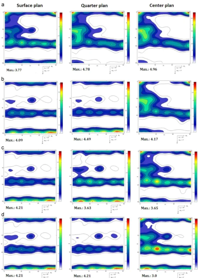
specimens) in three planes, i.e., surface, one-quarter and centre. The ODFs reveal that the texture and grain structure of the starting material is mostly random and homogenous and that the grains have a nearly equiaxed shape that is a common type of grain orientation during hot production (t¼12001C). The starting material reveals dominant {001}//ND and
γ
-fibres of which the(001)[11̄0] and (112)[11̄0] components show more intensity. The (001)[1 1 0] components indicate that certain of the austenite cube grains were present even after thefinished rolling operation due to the partial re-crystallisation of the
γ
-phase[8]because ofthe long distance of the slip planes in bcc material. Venegas[2]has shown that the cleavage along the {001}//ND planes propagated as the main cause of transgranular crack growth in the rolling plane as well as the crack deflection in the ND direction. It is known that the through-thickness microstructure and texture gradients inher-ited from hot rolling are often preserved to a certain extent after re-crystallisation; this observation applies in particular to the (001)[1 1 0] texture in the centre layers.
The
γ
and {110}//NDfibres are developed by rolling reductioncorresponding to the relative ODF (Fig. 3b) at the near surface layer. The shear deformation due to the friction between the rolls and strip distributes non-uniform shear deformation across the thickness. In bcc material, the {110} and {112} planes are the main slip planes and are responsible for deformation. In the vicinity of the grain boundaries regions, the crystal rotation is constrained by the interaction among the dislocations, neighbouring grains, and carbon in solution such that (112)[1 1 1] becomes the main slip system due to work hardening of the (110)[1 1 1] slip systems[13] and additional resistance to crack formation. In contrast, at the centre plane, dynamic re-crystallisation dominates to form {001}// NDfibres, and (001)[1 1 0] has the main effect of resistance in the material due to partial re-crystallisation of the
γ
-phase [9].Chowdhury et al. [21]reported that during annealing, the weak brass (110)[1 1 2] texture component with rotation towards the Goss (110)[1 0 0] was observed in re-crystallised austenite. During hot rolling, deformation mechanisms are strongly affected by the alloy composition. The amount of stacking fault energy (SFE) controls the cross-slip, thus allowing different deformation mechanisms to be activated at different stages of deformation. As the SFE decreases and the stacking faults become larger, cross-slip becomes more difficult and mechanical twinning is favoured. Most ferritic steels and high-to-moderate SFE metals tend to form extended stacking faults, and plastic deformation occurs by slip and long-range dislocation migration. These different lattice defects strongly influence the stress–strain response and the evolution of the texture during cold rolling. It could be concluded that slip is the deformation mechanism at the early stages of deformation of austenite, whereas twinning plays the dominant role at higher levels of deformation.
The intensity of the
α
-fibre texture components increasedduring rolling except for a remaining local texture maximum on thefibres at the (001)[1 1 0] component. This effect is deduced from the texture development in rolled bcc alloys. Generally, the
α
-fibre texture components steadily increase during rollingdefor-mation[22]. It is expected that the (112)[1 1 0] texture component strongly develops via plane strain deformation during rolling. The fact that this prominent deformation texture component is rather weak on the surface plane is therefore primarily attributed to re-crystallisation. In this respect, the drop in the orientation density of the (112)[1 1 0] orientation might be ascribed to the favourable orientation relationship for re-crystallisation between the (112) [1 1 0] deformation component and the (111)[1 1 2] re-crystallisation component, which is commonly observed in low carbon and alloy steels[17]. Although partial re-crystallisation was observed previously in other warm-rolled bcc alloys at high strains, the necklace-type morphology of the newly
re-crystallised grains, as observed in the current case, is rather uncommon due to the high SFE and dislocation annihilation that takes place widely during recovery. In other words, according to hot deformation conditions, the slip planes in the bcc structure, which are inactive at ambient temperature, are activated such that no necklace structures are observed along the former grain boundaries. In addition, the sample reveals both fully re-crystallised zones and certain rather long as-deformed grains that do not contain re-crystallised crystals.
The specimen that was water quenched following hot rolling exhibits a columnar grain structure near the surface plane, as shown in Fig. 3c, which is parallel to the heat conductivity direction. The formation of new strain-free grains is quite hetero-geneously distributed in the microstructure in the thermal choked region and creates a large number of dislocations during quench-ing. The texture consists primarily of orientations on the
γ
-fibre with a stronger (111)[1 1 2] and a weaker (111)[1 1 0] orientation. Rapid quenching in water followed by tempering after hot rolling creates a new microstructure that is rather inhomogeneous across the thickness. The higher intensities of the {001}fibre andγ
-fibrecould result from an appropriate choice offinishing temperature for hot rolling and optimal annealing conditions immediately following the last pass of hot rolling. Hot band annealing with phase transformation leads to a heightened intensity of the Goss and cube texture. It also has been confirmed that a coarse-grained hot band structure produces a higher intensity of Goss texture [14]. Fig. 3d shows that the tempered sample after quenching exhibits the ideal
γ
-fibre texture characterised by the presence of(111)[1 1 0] and (111)[1 1 2]. The
γ
-fibre texture represents the {111}//ND texture, where theo1114directions of the crystals are aligned along the normal direction of the sample. In contrast, the undesirable (001)o1104 texture component exists in the centre plane of all samples during thermomechanical paths. The results confirm that the crack would more likely nucleate and propagate in the centre because the lack of sufficient slip planes in this region makes it more prone to crack formation. The crystallographic texture is dominated by a strong (111)[1 1 2] texture component that might be attributed to the well known pronounced nucleation and growth of this orientation into deformed {111}ouvw4- and (112)[1 1 0]-oriented deformation microstructure[23]. Because we discussed that the (001)[1 1 0] texture component was strongly recovered in the centre layer of the material, we should also consider that the texture observed in Fig. 3d could result from both re-crystallisation and subsequent grain growth.3.3. EBSD Studies
400 and 325 grain boundaries were investigated in samples a-c, respectively, to assess whether the EBSD-based microtexture measurements are representative of the bulk sample[12].
The XRD and energy dispersive X-ray (EDX) tests were per-formed to confirm that thefinal structure after all thermomecha-nical heat treatment paths has a bcc lattice. This observation is also confirmed by the EBSD analysis, which produced no evidence of second phases in the matrix. Various thermomechanical paths, including hot rolling and post-treatment, demonstrated that the grain structure was uniform, randomly oriented, and nearly equiaxed due to re-crystallisation. The uniform structure in the initial sample plays an important role for texture evolution during subsequent processing because coarse grains and/or preferred casting textures usually entail strong inheritance effects. Micro-structure (and texture) inheritance implies that preferred casting textures could lead to warm rolling microstructures that undergo strong recovery instead of re-crystallisation [20]. Grain rotation during re-crystallisation has an important effect on non-uniform deformation due to dislocations trapped at the boundaries, which lead to new directions to reduce internal energy. Grain non-uniformity strain is related to two reasons:first, the absence of sufficient slip systems to satisfy the Von Mises criterion, and second, the plastic anisotropy that can be imposed by exterior restraints such as high-friction end pieces in a deformation experiment (which is likely what occurred during rolling) [24]. In this explanation for the difference grain shape and size observed in three different regions, the grains are fully re-crystallised at the near surface region, and dynamic recovery is observed at the centre plane.
At the centre plane, no relevant re-crystallised areas appear in the micrographs and EBSD maps. The texture evolution in this region is characterised by the steady evolution of (001)[0 1 0] and
(111)[1 1 2] (as Liu and Xie[16,21] have also reported), and the texture orientations of the resultant specimens after quenching and re-crystallisation correspond between the parent austenite and the product martensite phases. Thus, it could be deduced that the (001)[0 1 0], (010)[0 0 1], (111)[2 1 1] and martensitic texture components could originate from a single austenite (110)[1 1 0] texture. At the same time, column grains are related to bainite and martensite laths. In the surface layer of thefirst specimen (sample I),
α
-fiber is built up such that (111)[1 1̄0] and (111)[0 1̄1] wereintensively developed. In addition, at the near surface plane II, {110} ND is predominant, whereas (111)[1̄1̄2] has the most powerful texture component. The transition from the (111)[1 1 0] to (111)[1 1 2] orientation might be introduced by the re-crystallisation process and partially by the increasing deformation. Grain-size calculations were performed for each map, and 8mm, 12.5mm and 15mm sizes were assigned. As the strain increases due to shear deformation during rolling, large grains are divided into relatively large sub-grains that are gradually misoriented to form a number of new grain boundaries. It is interesting to note that only the largest grains rotate, whereas the smaller scale sub-boundaries maintain low misorientations. The grains that develop are a composite of original and newly accreted material sur-rounded by a mixture of migrated old and new grain boundaries [22]. In other words, development of the deformation zone occurs with large cumulative lattice misorientations adjacent to the grain boundaries, andfinally one sub-grain growth consumes the entire deformation zone such that a new grain-free nucleus is formed.
The strong through-thickness texture and microstructure image that are also observed in hot-rolled specimens are a consequence of the macroscopic gradients in shear and tempera-ture that occur during hot rolling, as explained previously. The centre layer is principally deformed by a plane strain deformation
condition, which leads to the formation of a strong deformation-induced (001)[0 1̄0] texture component. The grains in this region normally display elongated pancake-type morphology relative to the hot-rolled sheets intensively, as observed in the current case, when recovery dominates intensively. Recovery is particularly important for the preservation of certain
α
-fibre texturecompo-nents, particularly in the (001)[0 1̄0] orientation. Dislocation annihilation during recovery of high SFE material suppresses/ retards re-crystallisation. This process has a small nucleation rate for re-crystallisation because it typically encounters weak inher-ited deformation induced in the grain orientation gradients, which could endorse the formation of new HAGBs during nucleation. The rolling texture components in the centre layer, which essentially are shaped by a plane strain deformation condition, can generally be well ascribed in terms of crystal plasticity deformation models of bcc metals. These models all predict the formation of a strong (001)[0 1̄0] and (112)[1̄1̄1] texture component assuming certain grain scale relaxation, and either the (110)[1 1 1] plus (112)[1 1 1] or even the (110)[1 1 1], (112)[1 1 1] and (123)[1 1 1] slip systems are activated with similar critical resolved shear stress. The retention of a strong (001)[0 1̄0] texture component in conjunc-tion with recovered pancake grains is a common observaconjunc-tion in the centre plane of hot-rolled and annealed specimens[10].
The near surface layers of the hot-rolled specimen are categorised by a strong shear deformation. The values of the orientation distribu-tions of the shear components (110)[0 0 1] (Goss), (110)[1 1 2] and (4411)[1 1 1 1 8] correspond to the profile of the shear strain that results from the effect of the temperature on the stress and the through-thickness zone. The Goss orientation is known to be devel-oped due to shear strain in bcc metals [22]. The strong Goss component at the near surface of the hot-rolled specimen corre-sponds to the ideal shear texture. However, the Goss orientation is not only a strong shear texture component, but it is also typical of both as-rolled and re-crystallised grains after heavy shear deformation. This process induces a stable deformation-induced orientation in small volume fractions during heavy shear deformation and as a dominant re-crystallisation component when these small Goss oriented texture regions grow into the heavily strained neighbouring matrix. The {112}o1114 orientation, which is close to the ideal {4411}o111184shear component, is essentially introduced by shear deformation but not by re-crystallisation.
Crack formation susceptibility is primarily related to grain boundary distributions, i.e., mesotexture, that results from the texture that developed during deformation and re-crystallisation. The large number of {001}//ND grain orientations that developed at the centre layer of specimens leads to the harmful effects on crack resistance and facilitates crack formation. The main outlook is presented by Venegas et al.[25]; low-resistance cleavage paths associated with transgranular cracks in the rolling plane provide preferred paths for crack propagation, whereas grains with orien-tations within 151 of the ideal {001}//ND texture fibre can also enhance this propagation. Venegas explained that the {001} cleavage planes are oriented nearly parallel to the rolling plane; therefore, crack propagation along these planes and along the rolling plane of the pipe wall are facilitated considerably. Second, a large number of grains with an orientation of the {001}//NDfibre could facilitate intergranular crack propagation along the LABs shared by neighbouring grains with the same orientation. Undoubtedly, the LAGBs between these grains are of the low-energy type. However, contrary to what occurs in LAGBs shared by non{001}//ND grains, the {001} cleavage planes on both sides of a grain boundary shared by {001}//ND grains are close to the rolling plane. Therefore, as previously reported [16,17], LABs shared by {001}//ND also provide low-resistance paths to an intergranular cleavage-like propagation of damage in the rolling plane of the pipe wall[2,12,26].
At the near surface layers of specimens, crystallographic textures such as
γ
, {112}//ND, and {110}//ND were extensivelydeveloped. In addition to the reasons mentioned in the introduc-tion to this paper, which make pipeline steel with such a texture less susceptible to crack formation and propagation, other pro-cesses that help improve steel's resistance to crack initiation can be mentioned. Arafin et al. [27] has reported that the above-mentioned texture orientations hinder or impede transgranular crack propagation on the rolling plane. The
γ
-fibre grainorienta-tions have unique behaviours that can accumulate large plastic deformation if cracks are sufficiently close to induce interaction and coalescence. In these grains, the crystal lattice is able to rotate following the orientation of the maximum shear stress to mini-mise the effects of crack interaction. Thus, this process allows these materials to suffer large plastic deformation during the process without breakdown. This texture improves the resistance of the steel to cracking by reducing the driving force for growth of interacting cracks with a consequent reduction in the probability of coalescence of closely spaced, non-coplanar cracks. In addition, the surface plane of the group of samples is particularly attractive with respect to crack formation resistance because it exhibits a considerably reduced number of HABs. Consequently, an increased number of LABs can be found in this group with respect to the damage-stricken samples. Furthermore, the fact that
γ
- fibredominates the texture of two of these samples contributes to the increase with respect to LAGBs shared by the {001}//ND neigh-bouring grains and the well-known resistance offered by LABs to intergranular crack propagation. It has been reported[2]that LABs with a o1114 disorientation axis have lower grain–boundary energies than LABs with ao1004axis. Therefore, a steel with a strong {111}//ND texture is expected to show a reduced suscept-ibility to damage because of the increased presence of low-angle boundaries with the lowest possible energy.
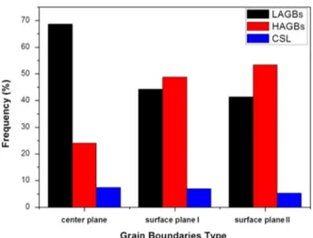
Shear deformation due to friction generates a large number of dislocations throughout the specimens; however, as mentioned previously, dislocation distributions across the thickness are inherently non-uniform. Moreover, water quenching followed by hot deformation leads to a significant increase in the dislocation density. Additionally, tempering at relatively high temperature (at 7001C) can enhance dislocation annihilation due to long-range migration. However, many re-crystallised grains are observed at EBSD maps, especially at the near surface layers. Thus, the grain boundary distributions with consideration of the grain boundary types (LAGBs, HAGBs, and CSL) and the relative frequencies obtained from EBSD maps are shown in Fig. 5. Static
crystallisation cannot occur bellow Tnr (non-recrystallisation temperature). Thus, strain accumulates at the sub-grains, leading to pancaking of the grain shapes, which is observed at the centre plane of the investigated specimen. Burke and Turnbull[28]have reported that during deformation and post-treatment, tempera-ture facilitates dislocation and long-range migration at the grain interior. Next, dislocations are trapped at the sub- grain and grain boundaries, a process that piles up dislocation and increases the dislocation density, leading to transfer of LAGBs into HAGBs and providing a driving force for re-crystallisation. Finally, the newly re-crystallised grains are surrounded by HAGBs, whereas the interiors of the grains contain relatively little dislocation. The significant increase observed at both surface planes of the inves-tigated specimen prove that re-crystallisation has taken place at the surface during post-heat-treatment. It is worth mentioning that the frequency of CSL boundaries is not changed significantly at the mentioned planes.
4. Conclusion
The principal conclusion obtained from the results is that it is feasible to improve the physical and mechanical properties of pipeline steels using crystallography texture control and grain boundary engineering.
- During rolling deformation, shear texture developed at the surface layer is dominated by {111}//ND and {110}//ND, which create additional resistance to damage.
- Thermomechanical paths create {111}//ND, {112}//ND and {110}//ND at the near surface planes.
- Shear strain induces a higher fraction of {110}//ND in the surface plane, and undesirable {001}//ND creates a lack of it in the centre plane.
- The number of high-angle grain boundaries is higher on the surface plane and gradually decreases towards the mid-thickness region.
- The values of the orientation concentrations of the shear components {110}o0014 (Goss), {110}o1124 and {4411} o111184 correspond to the profile of the shear strain that results from the effect of the temperature on the stress and the through-thickness zone.
Acknowledgements
The authors acknowledge the contributions of the research board of the Universidade Federal do Ceará forfinancial support and Laboratório de Caracterização de Materiais (LACAM) for providing research facilities for this work.
References
[1]J.P. Hirth, Theories of hydrogen induced cracking of steels, in: R. Gibala, R. F. Hehemann (Eds.), Hydrogen Embrittlement and Stress Corrosion Cracking, ASM International, Materials Park, OH, 1984, pp. 30–41.
[2]V. Venegas, F. Caleyo, T. Baudin, J.H. Espina-Hernández, J.M. Hallen, On the role of crystallographic texture in mitigating hydrogen-induced cracking in pipe-line steels, Corrosion Science 53 (2011) 4204–4212.
[3]B. Sander, D. Raabe., Texture inhomogeneity in a Ti–Nb-basedβ-titanium alloy after warm rolling and recrystallization, Materials Science and Engineering A 479 (2008) 236–247.
[4]M. Holscher, D. Raabe, K. Lucke, Relationship between rolling textures and shear textures in F.C.C. and B.C.C. metals, Acta metall, mater 42 (3) (1994) 879–886.
[5]D Raabe, K Lucke., AND TEXTURE, Microstructure of hot rolled steel, Scripta Metallurgica et Materialia 26 (1992) 1221–1226.
[6]K. Matsumoto, Y. Kobayashi, K. Ume, K. Murakami, K. Taira, K. Arikata, Hydrogen Induced Cracking Susceptibility of High-Strength Line Pipe Steels June 1986,, Corrosion 42 (6) (1986) 337–345.
[7]M.A. Mohtadi-Bonab, M. Eskandari, J.A. Szpunar, Texture, local misorientation, grain boundary and recrystallization fraction in pipeline steels related to hydrogen induced cracking, Materials Science&Engineering A 620 (2015) 97–106.
[8]I.L. Dillamoret, W.T. roberts, Rolling textures in F.C.C. and B.C.C. metals, Acta Metallurgica 12 (1964).
[9]Mohammad Masoumi, Esmaeil Emadoddin. Interface characterization and formability of two and three-layer composite sheets manufactured by roll bonding, Materials and Design 44 (2013) 392–396.
[10]S. Nafisi, M.A. Arafin, L. Collins, J. Szpunar., Texture and mechanical properties of API X100 steel manufactured under various thermomechanical cycles, Materials Science and Engineering A 531 (2012) 2–11.
[11] RECRYSTALLIZATION AND RELATED ANNEALING PHENOMENA. F.J. HUM-PHREYS. University of Manchester Institute of Science and Technology, UK. M. HATHERLY. University of New South Wales, Australia. 2004.
[12] Specification for Line Pipe. API SPECIFICATION 5L FORTY-THIRD EDITION, MARCH 2004 EFFECTIVE DATE: OCTOBER 2004 ERRATA DECEMBER 2004. [13]V. Venegas, F. Caleyo, J.L. Gonza´lez, T. Baudin, J.M. Hallen, R. Penelle, EBSD
study of hydrogen-induced cracking in API-5L-X46 pipeline steel, Scripta Materialia 52 (2005) 147–152.
[14]Eva Mazancová, Zdeněk Jonšta., Petr Wyslych, Karel Mazanec, Acicular ferrite and bainite microstructure properties and comparison of their physical metallurgy response 24.–26. 5 2005, Metal (2005).
[15]Chunming Wang, Xingfang Wu, Jie Liu, Ning’an Xu, Transmission electron microscopy of martensite/austenite islands in pipeline steel X70, Materials Science and Engineering A 438–440 (2006) 267–271.
[16]Z.Q. Sun, W.Y. Yang, J.J. Qi, A.M. Hu, Deformation enhanced transformation and dynamic recrystallization of ferrite in a low carbon steel during multipass hot deformation, Materials Science and Engineering A334 (2002) 201–206. [17]G.R. Speich, P.R. Swann, Martensitic transformation in iron-arsenic alloys,
Journal of Materials Science 12 (1977) 751–756.
[18] E. Anelli and D. Colleluori. Sour Service X65 Seamless Linepipe for Offshore Special Applications. Proceedings of the Eleventh (2001) International Off-shore and Polar Engineering Conference Stavanger, Norway, June 17–22, 2001. [19]M. Mujahid, A.K. Lis, C.I. Garcia, A.J. DeArdo, HSLA-100 Steels: Influence of Aging Heat Treatment on Microstructure and Properties, Journal of Materials Engineering and Performance 7 (2) (1998) 247.
[20]L. Germain, N. Gey, M. Humbert, P. Vo, M. Jahazi, P. Bocher, Texture heterogeneities induced by subtransus processing of near a titanium alloys, Acta Materialia 56 (2008) 4298–4308.
[21]Majid Nezakat, Hamed Akhiani, Majid Hoseini, Jerzy Szpunar, Effect of thermo-mechanical processing on texture evolution in austenitic stainless steel 316L, Materials Characterization 98 (2014) 10–17.
[22]U.F. Kocks, C.N. Tom´e, H.-R. Wenk, Texture and Anisotropy, Preferred Orientations in Polycrystals and their Effect on Material Properties, Cambridge University Press, Cambridge, UK, 1998.
[23]M.A. Arafin, J.A. Szpunar., A new understanding of intergranular stress corrosion cracking resistance of pipeline steel through grain boundary character and crystallographic texture studies, Corrosion Science 51 (2009) 119–128.
[24]R. Martyn, DRURY 1 and JANOS L. URAI. Deformation-related recrystallization processes, Tectonophysics 112 (1990) 235–253.
[25]V. Venegas, F. Caleyo, T. Baudin, J.H. Espina-Hernández, J.M. Halle, On the role of crystallographic texture in mitigating hydrogen-induced cracking in pipe-line steels 53 (12) (2011) 4204–4212.
[26]V. Venegas, F. Caleyo, J.M. Hallen, T. Baudin, R. Penelle, Role of crystallographic texture in hydrogen-induced cracking of low carbon steels for sour service piping, Metall. Mater. Trans. A 38 (2007) 1022–1031.
[27]M.A. Arafin, J.A. Szpunar., A new understanding of intergranular stress corrosion cracking resistance of pipeline steel through grain boundary character and crystallographic texture studies, Corrosion Science 51 (2009) 119–128.