Texture Study Across Thickness of API X70 Steel After Hot
Deformation and Different Posttreatments
M. MASOUMI,1,2L.F.G. HERCULANO,1A.A. ALMEIDA,1M. BE´ RESˇ,1 and H.F.G. DE ABREU1
1.—Department of Metallurgical and Materials Engineering, Federal University of Ceara´, Fort-aleza, Ceara´, Brazil. 2.—e-mail: [email protected]
In the present study, the texture heterogeneity across the thickness of API X70 steel subjected to hot deformation and different posttreatments was investigated. X-ray diffraction and electron backscattered diffraction were used to analyze crystallographic orientation and grain boundary distributions at the center and surface layers of specimens. The initial material was rolled at 1000°C to 67% reduction; then one deformed sample was cooled in air, and the others were quenched in water and finally tempered at 350°C and 700°C for 1 h. The shear strain generated by friction between rolls and strip induces heterogeneity across thickness. The results showed that in the center layer, the (001)[110] texture dominated in all specimens, whereas the {110}//ND component was developed at the surface layer. Furthermore, a local misori-entation histogram showed that the surface layer was subjected to a higher degree of deformation in comparison with the center layer due to additional shear deformation.
INTRODUCTION
The increasing demand for oil and natural gas forces the petroleum industry to improve materials used in sweet-and-sour services.1,2 API pipeline steels are employed widely to carry oil and gas for long distances for economic reasons and easy fabri-cation. Crack formation in these steels has become a severe problem. It is notable that cracks appear in the center regions of the cross section.3 During casting, the surface is solidified in early stages and then alloying elements are rejected into the center region where a hard segregation zone due to the formation of precipitates is developed. Therefore, in this segregation area, a heterogeneous deformation across the thickness can arise during rolling. In this regard, the control of the rolling schedule has been proposed to improve the microstructural and mechanical properties.
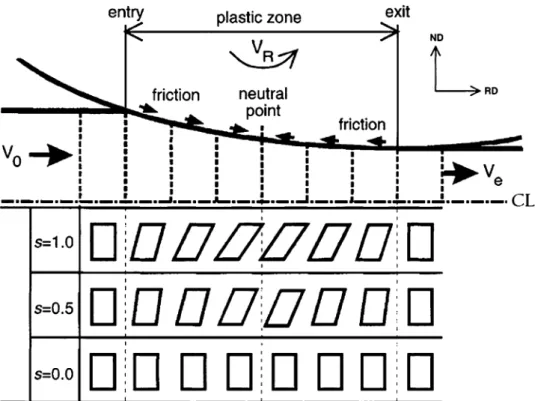
It is generally believed that plane strain condi-tions are applied during the rolling process. Asbeck and Mecking4 reported that due to the friction between the rolls and sheet plane, the significant amount of shear deformation was imposed. This amount reaches a maximum at the surface layers while remaining at about zero at the center ones. In
other words, a nonuniform deformation across the thickness develops various rolling textures at dif-ferent through-thickness layers of the sheet. It is expected that the center layer is affected by the plain strain condition, whereas the outer layers are affected by the friction between the rolls and the sheet surface; the shear deformation state is illus-trated in Fig.1. Therefore, the crystallographic texture and the grain boundary distribution through-thickness should be considered.
A study by Venegas et al.5has shown that grain boundary distributions and crystallographic texture can be used to improve mechanical properties due to increased crack resistance. They found that in X46 pipeline steel, an increase in {111}//ND (c-fiber) oriented grains improves the mechanical properties. Miyoshi et al.6showed that a strong {110} and {113}// ND texture develops in carbon-manganese steels during a severe rolling process, which increases fracture toughness and crack resistance. Arafin et al.7 reported that grain boundaries related to {110} and {111}//ND (c-fiber) are highly resistant, whereas boundaries associated with {001}//ND are very prone to crack formation in API X65. In addition, Watanabe8reported that an increase in high-angle grain boundaries (HAGBs) and coincident site lattice
JOM, Vol. 68, No. 1, 2016
DOI: 10.1007/s11837-015-1712-1
Ó2015 The Minerals, Metals & Materials Society
boundaries (CSLs) could provide a resistance path for crack propagation and an improvement in toughness and mechanical properties. Recently, King et al.9 showed that, besides the low-angle grain boundaries (LAGBs) and low R CSL boundaries, grain bound-aries related to low {hkl} index planes could resist crack initiations. Several special boundaries, such as
R3n,R11, and probablyR33c, play an important role in intergranular crack nucleation resistance of pipe-line steel.7
The objective of the current investigation is to study the effect of hot deformation and post–heat treatments, on textural changes across thickness. In this respect, x-ray diffraction (XRD) and electron backscattered diffraction (EBSD) analysis were carried out at the surface and center layers of each investigated specimen. Then the results were ana-lyzed by both texture analysis software MTEX and Channel 5 software. Significantly different crystal-lographic textures and grain boundary distributions were found across the thickness. These results support the hypothesis regarding the possibility of improving the mechanical properties by crystallo-graphic texture engineering through controlled hot rolling and post–heat treatment.
EXPERIMENTAL PROCEDURE
TableI shows the chemical composition of the as-received API X70 steel (sample a) used in this study. The sheets of initial material with an initial thickness of 8.5 mm were rolled at 1000°C to 2.8 mm (67% reduction) and then cooled in two different ways: One was cooled in air (sample b), and the others were water quenched followed by tempering at two different temperatures at 350°C and 700°C for 1 h (sample c and d, respectively).
Macro-texture measurements have been carried out at the center and surface layers of the rolled sheets perpendicular to normal direction (ND) to study the texture heterogeneity across the thick-ness. Three incomplete pole figures, {110}, {200}, and {211}, were measured by using a Phillips X-Pert goniometer equipped with a Co-tube. The orienta-tion distribuorienta-tion funcorienta-tion (ODF) of each sample was determined from the measured pole figures by using the M-tex software. Bunge’s angles were adopted to describe orientations, and the u2¼45 section of Euler space was used to display the computed ODFs.
Table I. Chemical analysis obtained by emission spectrometry technique of API X70 (in wt.%)
C Si Mn S Al Cu Cr P Ni Mo Nb Ti V
0.099 0.258 1.664 0.005 0.04 0.014 0.021 0.018 0.022 0.816 0.061 0.02 0.050
For the EBSD measurements, the specimen sur-faces were grinded with silicon carbide paper from grade 100 to 1200, followed by polishing with diamond paste (6, 3, and 1lm), and finally polished with 0.05-lm colloidal silica slurry for 3 h.
Microtexture analyses were performed by EBSD technique with the Oxford Channel 5 system attached to a Philips XL-30 scanning electron microscope. Scans of 4009120lm with a 0.5-lm step size were carried out at two regions: surface and center. All texture measurements were con-ducted on the plane perpendicular to the transverse direction (TD) of each specimen.
The local misorientation angle was calculated from EBSD data to evaluate and map local plastic strains in different regions of each sample. This is represented by the average misorientation angle between a given point and its nearest neighbors belonging to the same grain having misorientation angle<5°. Moreover, grain boundaries were defined from orientation maps and classified into (I) CSL, (II) LAGBs (misorientation angle between 5° and 15°), and (III) HAGBs (misorientation angle>15°).
RESULTS AND DISCUSSION Macrotexture Evolution During Thermome-chanical Treatment
To investigate texture heterogeneity across thick-ness, macrotexture analysis was conducted in both the surface and the center layer. Figure2shows the ODF atu2¼45of all specimens in both layers. The texture of the initial specimen (sample a) was random with weak {001}//ND and c-fiber compo-nents, which is common type of hot deformed texture. Furthermore, the {001}<011> component originated from the recrystallization {001}<010> component of fcc austenite, which showed that in the presence of {001} cleavage planes, it has a harmful effect on reduction of toughness.10
During the hot deformation and post–heat treat-ment, only modest texture changes at the center layer of samples a, b, and c were observed. In these samples, only a reduction in texture intensity was identified. Furthermore, in sample c, c-fiber was formed to be dominated by (111)[121] and (111)[112] (u1¼30and 90
;/¼55
;u2¼45
) components. In
addition, in sample d, a rotated Goss (110)[110] (u10;/¼90
;u2¼45
) texture has been
devel-oped by cube component transformation of the parent austenite phase.11 Also, in sample d, which was tempered at 700°C, a (110)[331] ( u1¼12;/¼ 90;u2¼45
) texture component was developed
instantly.
In the surface regions, because of shear strain induced by friction between the rolls and sheet surface, the texture demonstrated different behav-iors. During hot deformation, {110}//ND fiber was formed and (110)[001] (Goss texture) was developed as a result of shear deformation. Water quenching
followed by tempering at two different temperatures caused texture intensity to increase gradually, and finally (110)[111], (110)[112], and (110)[001] (u1¼35; 55
;and 90
;/¼90
;u2¼45
,
respec-tively) components reached the highest intensity. In this regard, Jonas12 has reported that the Goss component was transformed from the fully/partial recrystallization of the fcc austenite cube compo-nent. Taylor factor analysis of the Goss component (the yield strength of a given grain is obtained by multiplying the critical resolved shear strain for dislocation motion by the Taylor factor) has the highest yield strengths of all crystal orientations.11
Microtexture Evolution During Thermome-chanical Treatment
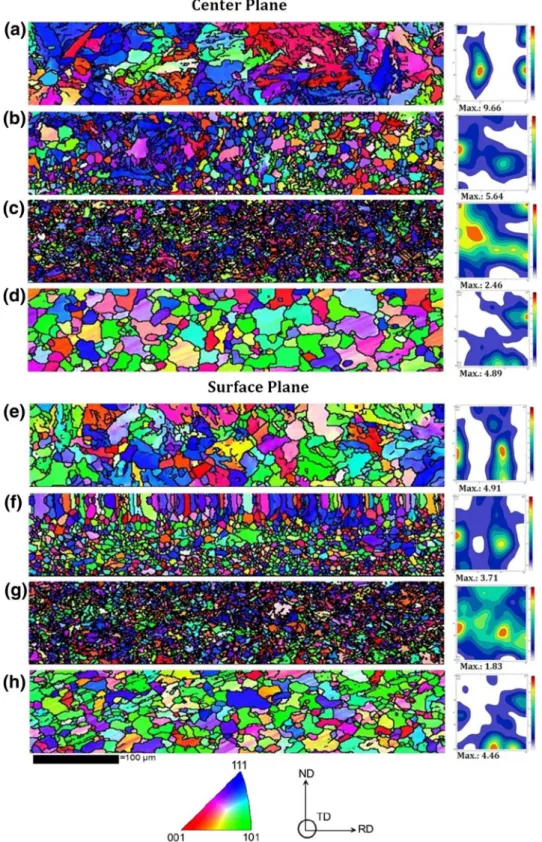
Figure3 represents the inverse pole figure (IPF) maps obtained by EBSD technique at both the center and surface layers of all specimens. To achieve a comprehensive estimation of the bulk materials, EBSD analysis was conducted on a large area (400lm 9120lm). The number of grains and grain sizes of all specimens were calculated and listed in Table II.
The fine and coarse grains coexist in the microstructure in hot rolled followed by air cooling (sample b), and a few grains exhibit abnormal growth in both regions. Most grains were slightly elongated, predominantly forming clusters aligned with the RD. This heterogeneity in the microstruc-ture induces high-stress concentration fields leading to deterioration of mechanical properties. However, abnormally grown grains were infrequent due to the high Nb and V content forming precipitates, which restricted grain growth.
According to Table II, the center layer of sample a consists of smaller grains than the surface layer, whereas average grain sizes in both regions of sample b and c are more homogeneous. Grain sizes decreased significantly during hot rolling due to generation of a large number of dislocations that are absorbed in grain boundaries. Water quenching followed by tempering at 700°C (sample d) produced large recovered grains in both regions. In addition, the center layer exhibited coarser grains when compared with the surface layer. The effect of grain size on mechanical properties is a challenging issue. On the one hand, it is expected that the grain boundaries can act as obstacles to crack propaga-tion; thus, toughness and mechanical properties increase. On the other hand, grain boundaries can stop dislocation motion, so pile-up dislocation with high stored energy would be formed that facilitates crack initiation and catastrophic fracture. The extent of this blocking effect depends on the bound-ary nature and can be quantified by a Hall–Petch equation,13 which states that plastic deformation leads to pile-up dislocations in front of boundaries. These pile-up dislocations can cause stress concen-trations on certain grain boundaries, as well as on Texture Study Across Thickness of API X70 Steel After Hot Deformation and Different
Posttreatments
their adjacent grains. When the stress concentra-tion is high enough to reach the critical value, a dislocation source is activated in adjacent grains and plastic deformation can progress into those
grains.14 In addition, smaller grains provide high stored strain energy in grain boundaries and may facilitate crack propagation.15 Thus, cracks can propagate in very small grains.
The ODFs related to each IPF are shown in Fig.3. Although texture analysis in the small specific region by EBSD could not present the crystallo-graphic orientations of the whole sample, it could
provide a lot of valuable and attributable informa-tion to better understand heterogeneity of texture during hot deformation and post–heat treatment across the thickness.
Fig. 3. IPF color maps and related ODFs of all specimens at center and surface planes: (a, e) sample a, (b, f) sample b, (c, g) sample c, and (d, h) sample d.
Texture Study Across Thickness of API X70 Steel After Hot Deformation and Different Posttreatments
At the center layer (sample a), a dominant texture component (111)[121] u1¼30and 90;/¼55
; ð
u2¼45Þ was observed. During hot deformation of sample b, {001}//ND andc-fiber were developed, and (223)[110] and (111)[0 11] components were domi-nated in the a-fiber. Then, after quenching, (001) [110] (rotated cube) was formed, which is a crystal-lographic orientation having the lowest mechanical property.11 In addition, the (112)[uvw] texture com-ponents as active slip planes were developed in this region. Finally, (223)[212] and (110)[112] components were formed by the recovery process in sample d.
At the surface layer, a (111)[011] texture compo-nent was developed as a result of recrystallization during hot rolling (t= 1200°C) of the as-received material. Thea,c-fiber, and {110}//ND are expected to develop due to shear strain during rolling. Sam-ples b and c illustrate the same dominate texture components andc-fiber as the main crystallographic orientation. Finally, as expected, (110)[112] (Brass component) and (110)[113] were observed in this region as a result of recrystallization of the cube component in parent austenite phase to develop {110}//ND texture components at the surface layer.
Figure4 shows the volume fraction of HAGBs, LAGBs, and CSL in both layers of all specimens. Grain boundaries with a misorientation angle of 1°<h<15° and 15°<h<62.81° are considered LAGB and HAGB, respectively.
Figure4demonstrates that the volume fraction of LAGBs decreased in both the center and surface regions during hot rolling. This steel has a high stacking fault energy (SFE) that permits a long-range dislocation motion through material leading to an annihilation of dislocation.
As discussed earlier, a recovery took place during hot deformation. However, sample c exhibited a large increase of LAGBs due to dislocation pile-up. A lower cooling rate led to the more homogeneous distribution of dislocations at the center layer. Generally, HAGBs have higher energy due to higher accumulation of dislocations. It is also believed that each system tends to reduce its internal energy. In this respect, HAGBs boundaries have a tendency to reduce the energy needed to reach the stable condi-tion. A reduction of stored energy in deformed grains would facilitate crack formation.
During rolling deformation, the crystallographic textures are likely to be composed of {110}//ND and c-fiber on the surface. Moreover, the CSL bound-aries that have lower internal energy in comparison with HAGBs tend to be more resistant to crack propagation. Therefore, a gradual increase of inter-nal energy is expected in samples b and c, whereas sample d tends to experience a decrease. In con-trast, Yazdipour et al.15found that the HAGBs have a high dislocation density, causing a higher stress concentration in the microstructure. Consequently,
Table II. Number of grains and grain sizes of all specimens at center and surface layers
Sample
Center plane Surface plane
Number of grains Diameterd(lm) Number of grains Diameterd(lm)
a 759 6.2±0.5 380 8.9±0.5
b 2467 4.1±0.5 2100 4.2±0.5
c 4041 2.8±0.5 4039 2.8±0.5
d 435 9.0±0.5 650 7.8±0.5
misorientation increases rapidly with rising dislo-cation density. Moreover, the HAGBs can restrict dislocation mobility, and hindered and piled-up dislocation tend to form micro-cracks.16
Figure5 shows a local misorientation angle obtained by EBSD analysis at both the center and surface layers of all specimens. Thermal residual stress can be induced because of a difference in the thermal expansion coefficient between austenite and ferrite during cooling after hot deformation and posttreatments.17 Local misorientation is defined as an average misorientation of a point with all of its neighbors in a grain. This parameter shows residual stress in single grains. The higher residual stress and dislocation accumulation due to higher local misorientation provide preferred path-ways for cracks.
Figure5demonstrates that samples b and d had the lower local misorientation in comparison with others at both layers due to recrystallization and recovery at higher temperature. The variation of local misorientation due to dislocation accumulation showed a nonuniform dislocation distribution across the thickness, which could provide an easier path for crack propagation. In contrast, samples b and d demonstrated the lowest stored energy, which could be beneficial for mechanical properties.
When the plastic strain increases, local misorien-tation increases inside grains. Nevertheless, the larger orientation gradients are found near grain boundaries, showing the localization of deformed areas. In fact, grains without subgrains show local misorientation values close to one, whereas sub-grains within a grain exhibit higher values (up to 5).18 Since this amount is generally higher at the surface layer, the residual stress should be also high and widely distributed over grains. Miyamoto et al.19 observed that dislocations tend to be accu-mulated on grain boundaries when moderate strains are applied.
CSL boundaries describe the relationship between the crystal orientations of grains adjacent to the grain boundaries. Watanabe8 found that grain boundary segregation and fracture have dif-ficulty occurring at LAGBs and at CSL boundaries. Intergranular cracks occur typically when there is a high frequency of random boundaries.
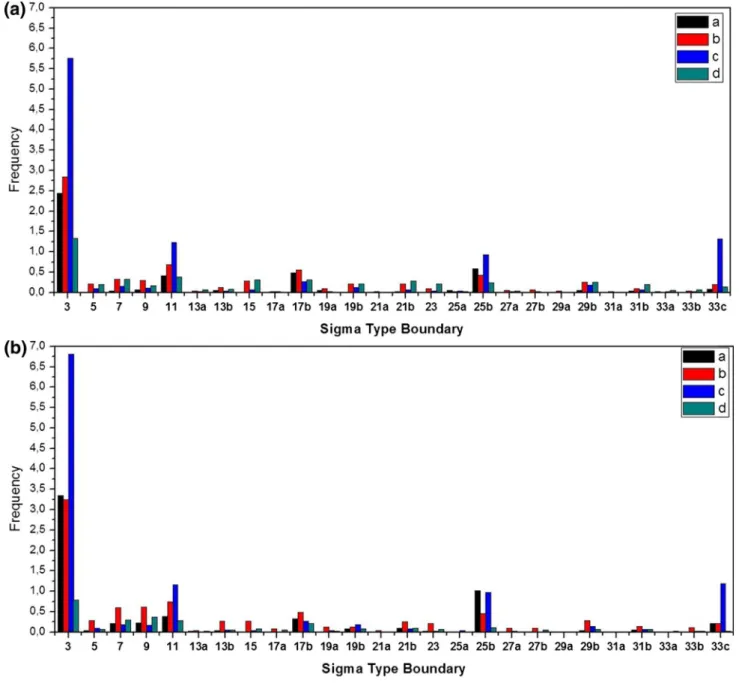
Figure6 shows the CSL boundaries histogram obtained by EBSD from both layers in all speci-mens. This figure demonstrates that some CSL boundaries have higher frequencies (i.e.,R3,R7,R9,
R11,R17b,R25b, andR33c). It is worth mentioning that CSL notation provides no information on the actual grain boundaries. For example, the crystal-lographic habit plane of coherent R3 twins is well defined, whereas this is not the case in incoherent
R3 twins. The higher the tilt and twist misorienta-tion angle between adjacent slip bands, the more effective the grain boundary acts as a barrier to the transmission of the plastic deformation into the neighboring grain.20
In addition, crystallographic orientation can influence the energy of grain boundaries and stored energy. Also, the grain boundary energy is not exclusively dependent on the misorientation between adjacent grains but also affected by the axis of misorientation and crystallographic texture. It is of great interest to investigate the induced deformation within the grains in specimens. The local change in the crystal orientation due to the accumulation of stored dislocations also provides useful information, which can be determined by EBSD.21 Figure7 shows the recrystallized, sub-structured, and deformed fraction by three different colors: red, yellow, and blue, respectively. These grain types were identified by the misorientation in each grain separately. It can be seen that the degrees of recrystallization increased during hot deformation in both the surface and center regions due to recrystallization. In general, a large number Fig. 5. Local misorientation angle at center (a) and surface (b) plane of all specimens.
Texture Study Across Thickness of API X70 Steel After Hot Deformation and Different Posttreatments
of deformed grains scattering is located at center regions, whereas in sample c, the whole sample was found as deformed. Interestingly, sample b shows the largest fraction of recrystallized grain in both sections due to recrystallization.
According to Refs. 6–10 the {111}//ND dominant texture provides enough slip planes to facilitate dislocation motion through grains. Because of stored energy decreases, the mechanical properties can be improved. In the current work, during hot deformation, recovery occurred with {110} and {111}//ND fiber components. Due to this recovery, the volume fraction of grains with<111> orienta-tion increased. In addiorienta-tion, reduced dislocaorienta-tion density by dislocations annihilation process led to
lower stored energy. It is worth mentioning that the recovery process was enhanced at the surface layer due to the higher deformation degree. During casting, a sheet plane solidified first so alloying elements such as Nb and V were rejected into the central region where precipitates form and retard recovery by pinning of dislocation. Thus, the center regions are prone to fracture and a deterioration of mechanical properties.
The recrystallized fraction in sample b was observed to be the highest. Figure7 shows that samples c and d have the lowest recrystallized fraction at surface area. Furthermore, sample c has higher stored energy, and thus, fracture damage is
probable. This demonstrates clearly the
heterogeneity of the crystallographic texture and grain boundary distributions across the thickness. Results obtained in this work can be used to enhance the accuracy of numerical models.22,23
CONCLUSION
In the current study, the macro- and microtexture evolution across the thickness of API X70 steel subjected to hot rolling and different post–heat treatments was investigated to obtain information about crystallographic texture and grain boundary distributions that should contribute to improved mechanical properties. The main conclusions of the study are summarized as follows:
– At the center layer, (001)[110] was the dominant texture component, whereas the {110}//ND tex-ture component was developed at the surface layer in all investigated specimens.
– The formation of the {110}//ND texture compo-nent at the surface layer is expected to improve ductility and crack resistance due to provision of abundant slip systems.
– Formation of the {001}//ND texture component in addition to precipitation in the center layer have a harmful effect on the mechanical properties. – A local misorientation histogram showed that
the surface layer was subjected to larger defor-mation in comparison with the center layer due to the additional shear strain generated by friction between the rolls and the sheet plane.
ACKNOWLEDGEMENT
The authors would like to acknowledge the financial support provided by CAPES.
REFERENCES
1. J. Moon, C. Park, and S.-J. Kim,Met. Mater. Int.18, 613 (2012). 2. M.-S. Joo, D.-W. Suh, J.H. Bae, and H.K.D.H. Bhadeshia,
Mater. Sci. Eng. A546, 314 (2012).
3. D. Hejazi, A.J. Haq, N. Yazdipour, D.P. Dunne, A. Calka, F. Barbaro, and E.V. Pereloma,Mater. Sci. Eng. A551, 40 (2012). 4. H.O. Asbeck and H. Mecking,Mater. Sci. Eng. A34, 111 (1978). 5. V. Venegas, F. Caleyo, T. Baudin, J.H. Espina, and J.M.
Hallen,Corros. Sci.53, 4204 (2011).
6. E. Miyoshi, T. Tanaka, F. Terasaki, and A. Ikeda,J. Eng. Ind.98, 1221 (1976).
7. M.A. Arafin and J.A. Szpunar,Corros. Sci.51, 119 (2009). 8. T. Watanabe,J. Phys. Colloq.46, 555 (1985).
9. A. King, G. Johnson, D. Engelberg, W. Ludwig, and J. Marrow,Science321, 382 (2008).
10. M.S. Joo, D.-W. Suh, J.-H. Bae, and H.K.D.H. Bhadeshia,
Mater. Sci. Eng. A546, 314 (2012).
11. R.W. Revie, Oil and Gas Pipelines Integrity and Safety Handbook(Hoboken, NJ: Wiley, 2015), pp. 176–177. 12. J.-J. Jonas,Microstructure and Texture in Steels(Springer,
2009), pp. 3–17.
13. N.J. Petch,Eng. Fract. Mech.28, 529438 (1987).
14. O. Du¨ber, B. Ku¨nkler, U. Krupp, H.-J. Christ, and C.-P. Fritzen,Int. J. Fatigue28, 983 (2006).
15. N. Yazdipour, A.J. Haq, K. Muzaka, and E.V. Pereloma,
Comput. Mater. Sci.56, 49 (2012).
16. H.K. Birnbaum,Mechanisms of Hydrogen Related Fracture of Metals (Urbana-Champaign: Materials Research Labo-ratory, University of Illinois, 1989), pp. 1–19.
17. R. Badji, T. Chauveau, and B. Bacroix,Mater. Sci. Eng. A
575, 94 (2013).
18. S. Nafisi, J. Szpunar, H. Vali, and R. Ghomashchi,Mater. Charact.60, 938 (2009).
19. H. Miyamoto, D. Saburi, and H. Fujiwara,Eng. Fail. Anal.
26, 108 (2012).
20. T. Zhai, A.J. Wilkinson, and J.W. Martin,Acta Mater.48, 4917 (2000).
21. M. Kamaya, A.J. Wilkinson, and J.M. Titchmarsh, Nucl. Eng. Design235, 713 (2005).
22. L. Novotny´,Metalurgija49, 416 (2010).
23. M. Halama, D. Jerolitsch, J. Zˇ ilkova´, R. Dzedzina, and P. Linhardt,Paper presented at Eurocorr 2010(Moscow, Rus-sia, 13–17 September 2010), pp. 1–8.
Fig. 7. EBSD recrystallization fraction map at center and surface layers: (a, e) sample a, (b, f) sample b, (c, g) sample c, and (d, h) sample d.
Texture Study Across Thickness of API X70 Steel After Hot Deformation and Different Posttreatments