AN EFFICIENT METHOD FOR MODELLING THE
NONLINEAR TRAIN-BRIDGE INTERACTION
Sérgio Gonçalves Moreira das Neves
2016
A dissertation presented to the Faculty of Engineering of the University of Porto for the degree of Doctor in Civil Engineering.
Supervisor: Prof. Alvaro Azevedo (FEUP, Portugal) Co-Supervisor: Prof. Rui Calçada (FEUP, Portugal)
“An expert is someone who knows some of the worst mistakes that can be made in his subject, and how to avoid them.”
vii
ABSTRACT
An accurate, robust and efficient vehicle-structure interaction (VSI) method, referred to as the direct method, has been developed to help close the gap between commercial finite element (FE) and multibody simulation (MBS) programs. FE programs can accurately simulate the deformation of the vehicles and structures but have simplified contact formulations that cannot efficiently take into account normal and tangential contact forces. MBS programs can efficiently account for the latter but do not simulate the deformations of the structure with the same level of detail. Over the last decades, there has been a proliferation of studies proposing VSI methods in order to close this gap. However, these studies often lack a thorough comparison between the proposed and existing methods. A comprehensive literature review covering VSI methods based on equilibrium of contact forces, variational formulations and condensation techniques is presented here. The direct method proved to be the most suitable approach.
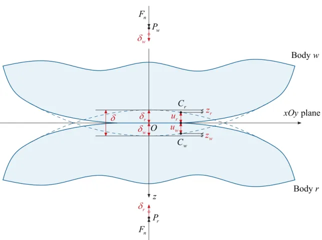
The direct method is implemented in MATLAB and the structures and vehicles are modelled using ANSYS. This program allows the development of models with a high degree of complexity and with several types of FE. This methodology is also valid when the vehicles are modelled using multibody systems. An enhanced node-to-segment contact element that includes a Hertzian spring, which relates the forces acting at the contact region with its local deformations, is proposed. The constraint equations that relate the displacements of the vehicles and structure are imposed only when contact occurs; this allows for an effective simulation of the loss of contact. The results obtained with the direct method are compared with semi-analytical solutions and those calculated with ANSYS in order to validate the accuracy and efficiency of the proposed method.
The passage of the Korean high-speed train over a railway viaduct is analysed using the direct method. Special focus is given to the development and validation of the numerical models. The model of the viaduct is calibrated using a FE model updating technique that compares the numerical response with measured data. The influence of isolated defects and periodic irregularities, local deformations of the viaduct slab and force-deflection relationship of the Hertzian spring on wheel-rail contact forces and vertical accelerations of the slab is analysed in detail.
ix
RESUMO
Na presente dissertação é proposto um método preciso, robusto e eficiente para analisar a interação veículo-estrutura, designado por método direto, tendo em vista colmatar a lacuna existente entre programas comerciais de elementos finitos e de sistemas multicorpo. Os programas de elementos finitos simulam adequadamente as deformações dos veículos e das estruturas, mas utilizam formulações simplificadas que não permitem considerar eficientemente as forças normais e tangenciais de contacto. Os programas de simulação de sistemas multicorpo consideram adequadamente estas forças mas não simulam as deformações das estruturas com o necessário nível de detalhe. Nas últimas décadas, tem havido uma proliferação de estudos propondo métodos de interação veículo-estrutura por forma a colmatar esta lacuna. No entanto, estes carecem de uma comparação rigorosa com os métodos existentes. É apresentada neste trabalho uma revisão bibliográfica exaustiva de métodos deste tipo baseados no equilíbrio das forças de contacto, formulações variacionais e técnicas de condensação. O método direto provou ser a abordagem mais adequada.
O método direto encontra-se implementado em MATLAB. As estruturas e os veículos são modelados com o programa ANSYS, que permite desenvolver modelos complexos com diferentes tipos de elementos finitos. Esta metodologia é igualmente válida quando os veículos são modelados com sistemas multicorpo. É proposto um elemento de contacto ponto-elemento que inclui uma mola de Hertz que relaciona as forças com as deformações na região de contacto. As equações de restrição que relacionam os deslocamentos dos veículos e da estrutura são apenas impostas quando ocorre contacto, permitindo assim uma simulação efetiva da perda de contacto. Os resultados obtidos com recurso ao método direto são comparados com soluções semi-analíticas e com os resultados calculados com o programa ANSYS por forma a validar a precisão e eficiência do método proposto.
O método direto foi aplicado na análise da passagem de um comboio de alta velocidade Coreano sobre um viaduto ferroviário. É dedicada uma atenção especial ao desenvolvimento e validação dos correspondentes modelos numéricos. O modelo do viaduto é calibrado com recurso a uma metodologia que compara a resposta numérica com resultados experimentais. A influência das irregularidades pontuais e distribuídas da via, das deformações locais da laje e da relação força-deformação da mola de Hertz nas forças de contacto roda-carril e nas acelerações verticais da laje é analisada detalhadamente.
xi
LIST OF PUBLICATIONS
The following publications have been derived from the development of this thesis.
Articles in indexed international journals
• Montenegro, P. A., Neves, S. G. M., Calçada, R., Tanabe, M., & Sogabe, M. (2015). Wheel-rail contact formulation for analyzing the lateral train-structure dynamic interaction. Computers & Structures, 152, 200-214. DOI:10.1016/j.compstruc. 2015.01.004.
• Neves, S. G. M., Montenegro, P. A., Azevedo, A. F. M., & Calçada, R. (2014). A direct method for analyzing the nonlinear vehicle-structure interaction. Engineering
Structures, 69, 83-89. DOI:10.1016/j.engstruct.2014.02.027.
• Neves, S. G. M., Azevedo, A. F. M., & Calçada, R. (2012). A direct method for analyzing the vertical vehicle-structure interaction. Engineering Structures, 34, 414-420. DOI:10.1016/j.engstruct.2011.10.010.
Proceedings in international conferences
• Montenegro, P. A., Neves, S. G. M., Calçada, R., Tanabe, M., & Sogabe, M. (2014). A nonlinear vehicle-structure interaction methodology for the assessment of the train running safety. In A. Cunha, E. Caetano, P. Ribeiro, & G. Müller (Eds.), EURODYN
2014 - 9th International Conference on Structural Dynamics. Porto, Portugal.
• Montenegro, P. A., Neves, S. G. M., Calçada, R., Tanabe, M., & Sogabe, M. (2014). A three dimensional train-structure interaction methodology: Experimental validation. In J. Pombo (Ed.), Railways 2014 - 2nd International Conference on
Railway Technology: Research, Development and Maintenance. Ajaccio, Corsica.
Stirlingshire, UK: Civil-Comp Press. DOI:10.4203/ccp.104.71.
• Neves, S. G. M., Montenegro, P. A., Azevedo, A. F. M., & Calçada, R. (2014). A direct method for analyzing the nonlinear vehicle-structure interaction in high-speed railway lines. In J. Pombo (Ed.), Railways 2014 - 2nd International Conference on
Railway Technology: Research, Development and Maintenance. Ajaccio, Corsica.
• Montenegro, P. A., Neves, S. G. M., Azevedo, A. F. M., & Calçada, R. (2013). A nonlinear vehicle-structure interaction methodology with wheel-rail detachment and reattachment. In M. Papadrakakis, N.D.Lagaros, & V. Plevris (Eds.), COMPDYN
2013 – 4th International Conference on Computational Methods in Structural Dynamics and Earthquake Engineering. Kos Island, Greece.
• Neves, S., Azevedo, A., & Calçada, R. (2008). Development of an efficient finite element model for the dynamic analysis of the train-bridge interaction. IABMAS
2008 – 4th International Conference on Bridge Maintenance, Safety and Management. Seoul, Korea.
• Azevedo, A., Neves, S., & Calçada, R. (2008). Dynamic analysis of the train-bridge interaction: an accurate and efficient numerical method. EURODYN 2008 - 7th
xiii
ACKNOWLEDGEMENTS / AGRADECIMENTOS
The work carried out in this thesis lasted longer than I had anticipated and it would have lasted even longer without the support of all who have accompanied me during this period. I want to express my sincere gratitude to all friends and colleagues whose friendship, understanding and support made this journey easier. In particular, I would like to express my special appreciation and thanks to:
• My supervisor, Prof. Álvaro Azevedo, for his unconditional support, mentorship and depth of knowledge demonstrated throughout my work. The lessons learnt from this are an invaluable tool for the future.
• My co-supervisor, Prof. Rui Calçada, for his motivation and broad range of knowledge in the field of railways. Being part of the railway research group lead by him, Centro de Saber da Ferrovia (CSF), has been an enriching experience.
• My thesis committee, Prof. José Goicolea, Prof. Constança Rigueiro, Prof. Cecília Vale and Prof. Rui Faria, for the insightful discussion and encouragement, which were an important contribution for improving this work.
• Fundação para a Ciência e a Tecnologia for the financial support provided under Grant No. SFRH/BD/39190/2007.
• REFER for the data provided regarding the Alverca viaduct and all the support given to the ambient vibration tests carried out.
• To all my colleagues of the Institute of Railway Research (IRR) of the University of Huddersfield, in particular Dr. Yann Bezin and Prof. Simon Iwnicki, for all the support, patience and motivation. I am very grateful for having been given the opportunity to continue my research career at IRR.
• My friend Dr. Pedro Montenegro for all his friendship, patience and collaboration in the development and implementation of the vehicle-structure interaction algorithm presented in this work. Working closely with him has been a very enriching experience.
• Profs. Rui Faria and João Guedes, from the Faculty of Engineering of the University of Porto, for the very helpful discussions that we had throughout this work.
• My friend Diogo Ribeiro for all the helpful discussions and support given.
• My friend Emily Hurst for all the support given and for reviewing the English of a Latin.
• My friends Dimitrios Kostovasilis, Gareth Tucker, Ilaria Grossoni and Yousif Muhamedsalih for reviewing my work.
• All friends of the research group CSF, namely, Alejandro Tejada, Andreia Meixedo, Cristiana Bonifácio, Cristina Ribeiro, Diogo Ribeiro, Joana Delgado, João Barbosa, João Francisco, João Rocha, Joel Malveiro, Nuno Ribeiro, Nuno Santos and Pedro Jorge.
• All other friends of the Faculty of Engineering, namely, Alexandre Costa, Fernando Bastos, Isabel Horta, Luís Macedo, Mário Marques, Miguel Araújo, Miriam López, Nuno Pereira, Ricardo Monteiro, Rui Barros and Sara Rios.
• To my best friend, Bruno Silva, for sharing the most important moments of my life. • À minha família mais chegada, nomeadamente, aos meus pais, avós, ao meu irmão
Pedro e cunhada Ângela, bem como ao meu sobrinho e afilhado Tiaguinho – a todos eles dedico esta tese, com a convicção de que o maior presente que lhes posso dar é o da sua conclusão, por forma a poder finalmente ter a disponibilidade que eles merecem.
• Agradeço duma maneira muito especial à minha querida avó Aurora, que faleceu no passado mês de Outubro, por todo o carinho e apoio que sempre me deu.
xv
CONTENTS
1 Introduction ... 1
1.1 Background ... 1
1.2 Objectives and scope ... 3
1.3 Outline of the thesis ... 4
2 Overview of vehicle-structure interaction methods ... 7
2.1 Introduction ... 7
2.2 Direct equilibrium of contact forces ... 10
2.2.1 Formulation of the equations of motion ... 10
2.2.2 Direct integration of the equations of motion ... 11
2.2.3 Contact constraint equations ... 12
2.2.4 Direct method ... 13
2.2.5 Iterative methods ... 13
2.2.6 Numerical example ... 17
2.3 Variational formulations ... 20
2.3.1 Formulation of the equilibrium equations ... 21
2.3.2 Lagrange multiplier method ... 22
2.3.3 Penalty method ... 23
2.4 Condensation methods ... 24
2.5 Concluding remarks ... 26
3 Wheel-rail contact mechanics ... 29
3.1 Introduction ... 29
3.2 Basic concepts and definitions ... 30
3.3 Hertz theory ... 31
3.3.2 Pressure distribution and elastic deformation ... 39
3.4 Numerical example ... 48
3.5 Concluding remarks ... 56
4 An efficient method for analysing the vehicle-structure interaction ... 57
4.1 Introduction ... 57
4.2 Vehicle-structure interaction method ... 58
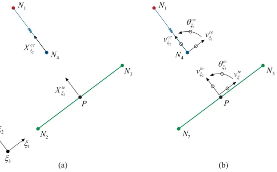
4.2.1 Contact and target elements ... 58
4.2.2 Formulation of the equations of motion ... 60
4.2.3 Direct integration of the equations of motion ... 62
4.2.4 Formulation of the contact constraint equations ... 62
4.2.5 Complete system of equations ... 63
4.3 Semi-analytical solutions ... 65
4.3.1 Beam transverse vibration theory ... 65
4.3.1.1 Equation of undamped motion ... 65
4.3.1.2 Vibration mode shapes and frequencies ... 66
4.3.1.3 Modal analysis of forced dynamic response ... 68
4.3.2 Moving force ... 68
4.3.3 Moving mass ... 69
4.3.4 Moving sprung mass ... 70
4.4 Numerical examples and verification ... 72
4.4.1 Simply supported beam subjected to one moving sprung mass ... 72
4.4.2 Simply supported beam subjected to fifty moving sprung masses ... 74
4.5 Concluding remarks ... 79
5 Enhanced nonlinear contact element ... 81
5.1 Introduction ... 81
Contents xvii
5.2.1 Enhanced contact element ... 81
5.2.2 Formulation of the equations of motion ... 83
5.2.3 Incremental formulation for nonlinear analysis ... 85
5.2.4 Formulation of the contact constraint equations ... 86
5.2.5 Complete algorithm ... 88
5.3 Numerical examples and verification ... 90
5.3.1 Two simply supported spans modelled with 2D beam elements ... 90
5.3.2 Two simply supported spans modelled with 3D solid elements ... 95
5.3.3 Inclined rigid beam ... 97
5.4 Concluding remarks ... 99
6 Modelling and dynamic analysis of the train-track system ... 101
6.1 Introduction ... 101
6.2 Numerical modelling of the KHST ... 102
6.2.1 General description ... 102
6.2.2 Finite element model ... 103
6.2.3 Static and modal analyses ... 108
6.2.4 Simplified model of the KHST ... 110
6.3 Numerical modelling of the track ... 112
6.3.1 General description ... 112
6.3.2 Geometrical and mechanical properties ... 113
6.3.3 Finite element model ... 115
6.3.4 Response in the frequency domain ... 116
6.3.5 Damping of the track ... 118
6.3.6 Optimisation of the mesh ... 118
6.4 Dynamic response of the train-track system ... 122
6.4.1 Influence of the 2D track model ... 123
6.4.3 Influence of the numerical dissipation of the time integration scheme ... 133
6.4.4 Comparison between the MATLAB and ANSYS programs ... 135
6.5 Concluding remarks ... 138
7 Case study of the Alverca railway viaduct ... 141
7.1 Introduction ... 141
7.2 Numerical modelling of the Alverca viaduct ... 142
7.2.1 General description ... 142
7.2.2 Geometrical and mechanical properties ... 144
7.2.3 Finite element model ... 145
7.2.4 Modal parameters ... 147
7.2.5 Ambient vibration test ... 148
7.2.6 Model updating techniques ... 151
7.2.6.1 Sensitivity analysis ... 151
7.2.6.2 Optimisation algorithms ... 153
7.2.6.3 Automatic mode pairing ... 154
7.2.6.4 Optimisation of the mesh ... 155
7.2.6.5 Model updating of the Alverca viaduct ... 158
7.2.7 Damping of the viaduct ... 164
7.3 Dynamic response of the train-viaduct system ... 166
7.3.1 Influence of the transition between plane track and viaduct ... 166
7.3.2 Influence of the track irregularities ... 169
7.3.2.1 Isolated defects ... 169
7.3.2.2 Periodic irregularities ... 176
7.3.3 Influence of the Hertzian contact spring ... 179
7.3.4 Comparison between the MATLAB and ANSYS programs ... 181
Contents xix
8 Conclusions and future developments ... 189
8.1 Conclusions ... 189
8.2 Future developments ... 192
Appendix A – A 2-by-2 block factorisation solver ... 195
Appendix B – A 3-by-3 block factorisation solver ... 197
Appendix C – Validation of the model updating techniques ... 201
xxi
ABBREVIATIONS AND SYMBOLS
The abbreviations, symbols and notations used throughout this thesis are listed below.
ABBREVIATIONS
2D / 3D Two-dimensional / Three-dimensional d.o.f. Degree Of Freedom
EC European Commission
EN European Norm
FE Finite Element
KHST Korean High-Speed Train MAC Modal Assurance Criterion MBS Multibody Simulation
SYMBOLS
a Transverse displacement a Nodal displacements vector
a, b Semi-axes of the elliptical contact area
0
a Amplitude of the irregularity
0
A to A5 Constants of the HHT-α method
A Cross-sectional area / Hertz geometric parameter
B Hertz geometric parameter C Viscous damping matrix
C1, C2 Geometric constants used in the Hertz theory
D Matrix relating the contact forces to the equivalent nodal loads / Diagonal matrix
E Young’s modulus
f Natural cyclic frequency
F Load vector
g Acceleration of gravity
G Shear modulus
h Gap between two undeformed surfaces
H Matrix relating the nodal displacements to the displacements of the contact nodes and auxiliary points of the target elements
i Iteration counter
I Moment of inertia
I Identity matrix
k Spring stiffness / Ellipse axes ratio
K Stiffness matrix
k Parameter used to control the wavelength of the isolated defect K Effective stiffness matrix
kh Linearized value of the stiffness of the Hertzian spring around the static wheel load
Kh Constant of the Hertz force law
L Span length
L Lower triangular matrix
m Mass per unit length / Hertz coefficient
M Mass matrix
n Hertz coefficient
N1 Contact node of the wheel
N2, N3 Nodes of the target element of the structure
N4 Node of the Hertzian spring of the contact element
p Applied pressure distribution / Applied force
P Auxiliary internal point of the target element P Externally applied nodal loads vector
r Rolling radius of the wheel
r Vector of irregularities between the contact and target elements 0
r Nominal rolling radius of the wheel
R Principal radius of curvature
Abbreviations and symbols xxiii
S Support reactions vector U Upper triangular matrix
v Displacement of a point / Vehicle speed
x, y, z Cartesian coordinate system X Contact forces vector
α Parameter of the HHT-α method / Penalty parameter
β Parameter of the Newmark method
γ Parameter of the Newmark method / Contact angle
δ Deflection / Displacement
Δt Time step
ε Tolerance
θ Auxiliary angle used in the Hertz theory / Rotation of a point
λ Lagrange multiplier / Wavelength
ν Poisson’s ratio
ξ1, ξ2, ξ3 Local coordinate system of the contact pair
ρ Density / Spectral radius Φi Eigenvector of mode i ψ Residual forces vector
ω Natural circular frequency NOTATIONS
( )
⋅∆ Incremental or variation of (·)
( )
⋅⋅ First time derivative of (·)( )
⋅⋅⋅ Second time derivative of (·)( )
⋅ Norm of (·)( )
⋅ 0 Referred to the initial value of (·)( )
⋅bg Referred to the bogie( )
⋅cb Referred to the carbody( )
⋅ ce( )
⋅exp Referred to experimental( )
⋅F Referred to the free d.o.f.( )
⋅ iReferred to the iteration i
( )
⋅ I Referred to the free d.o.f. (excluding R and Y types)( )
⋅ Iˆ Referred to the free d.o.f. of the structure( )
⋅I~ Referred to the free d.o.f. of the vehicles( )
⋅ num Referred to numerical( )
⋅ p Referred to the primary suspension( )
⋅P Referred to the prescribed d.o.f.( )
⋅ r Referred to the rail( )
⋅R Referred to the free d.o.f of the contact elements (excluding Y type)( )
⋅ s Referred to the secondary suspension( )
⋅tReferred to the previous time step
( )
⋅t+∆tReferred to the current time step
( )
⋅ teReferred to the target element
( )
⋅theoReferred to theoretical
( )
⋅updtReferred to updated
( )
⋅ w Referred to the wheel( )
⋅ws Referred to the wheelset( )
⋅YReferred to the d.o.f of the internal nodes added by the contact elements
1
1 INTRODUCTION
1.1 BACKGROUND
The railway sector faces very demanding challenges that are critical for the well-being and mobility of people. The greenhouse gases produced by human activities are causing global warming and changes to the climate. According to the Intergovernmental Panel on Climate Change (IPCC), without urgent action climate changes will lead to severe and irreversible impacts across the planet. At the 21st United Nations Climate Change
Conference, held in Paris in December 2015, 195 countries adopted the first legally binding global climate agreement (Paris Agreement, 2015). This agreement defines the actions necessary to limit the rise in global average temperature to below 2°C when compared to pre-industrial levels. In order to achieve this goal, the European Commission (EC) published a roadmap setting the target of cutting the emissions by 80-95% below 1990 levels by 2050 (White paper, 2011). The EC also published a study showing that a reduction of at least 60% of emissions is required from the transport sector to achieve the defined targets by 2050 (EC communication, 2011). The CO2 emissions in 2013 from
different modes of passenger transport are shown in Fig. 1.1 (EEA Report n. 7, 2014), with rail transport having the lowest values. The average number of passengers per vehicle considered is also indicated in the figure.
Figure 1.1 – CO2 emissions in 2013 by transport mode (train, small and large cars, bus, two-wheeler and aircraft).
Besides having a low environmental impact, rail transport also plays a critical role in the mobility of people and goods, thus contributing to the economic and social development of most countries. The EC policy states that by 2050 most of medium-distance passenger transport should go by rail and that 50% of road freight over 300 km should shift to other modes such as rail or waterborne transport (White paper, 2011). To meet these goals, the length of high-speed rail network that existed in 2011 has to be tripled by 2030 and a coherent network including links and accessibility between all major cities and core network airports has to be developed by 2050. To achieve this, it would be necessary to triple the number of kilometres of lines built annually with an estimated investment of 300 to €500 billion (Civity, 2013). These objectives provide unique research opportunities such as Shift2Rail, which is a joint effort of several stakeholders of the European rail sector to drive innovation. This project has an estimated budget of €920 million (Shift2Rail, 2014).
The ambitious plans set for the transport sector lead to a high rate of construction of railway lines. Also, high-speed lines, when compared to conventional lines, have to satisfy stricter design requirements such as larger curve radii and smaller gradients. These factors result in less flexibility for defining the rail corridors and often lead to lines with an increased ratio of bridges, viaducts and tunnels. There are several lines in China and Japan in which the total length of bridges, viaducts or tunnels comprises more than 80% of the total length of the line (Montenegro, 2015). The expansion of the European high-speed rail network might lead to some lines in which the ratio of these types of structures is around 50% (Civity, 2013). All these factors will inevitably lead to a significant number of cases in which the vehicle-structure interaction has to be taken into account. For example, Yau et
al. (1999) concluded that the design of high-speed railway bridges can be mainly governed
by serviceability limit states, such as the passenger comfort, rather than by the ultimate limit states of the bridge. Zhai and Cai (1997) concluded that the wheel and rail irregularities induce severe dynamic disturbances and, as a consequence, large impact forces occur; this results in damage to the wheels, rails and other vehicle and track components. Taking into account the train-track interaction is also essential for predicting railway-induced vibrations such as the free-field response (Lombaert & Degrande, 2009). These vibrations can cause disturbance to nearby residents, malfunctioning of sensitive equipment and damage to buildings (Jones & Hunt, 2011). Also, according to Thompson (2009), the rolling noise caused by the wheel-rail interaction is the most important source of noise from railway operations. Therefore, having accurate, robust and efficient
Introduction 3
algorithms for analysing the vehicle-structure interaction is an essential prerequisite for achieving the challenging objectives mentioned above.
1.2 OBJECTIVES AND SCOPE
Do the available methods for analysing the vehicle-structure interaction simultaneously satisfy the fundamental requirements in terms of accuracy, robustness and efficiency? Commercial finite element (FE) programs can accurately simulate the nonlinear behaviour and deformation of the vehicles and structures but have simplified contact formulations that cannot efficiently take into account the wheel and rail geometry and the normal and tangential forces transmitted across the contact interface. Multibody simulation (MBS) programs provide comprehensive libraries of detailed vehicle models and can efficiently take into account the wheel and rail geometry, but might not simulate the deformation of the structure adequately. Over the last decades, the scientific community has witnessed a proliferation of studies proposing different vehicle-structure interaction methods in order to close the gap between FE and MBS programs. However, these studies often lack a thorough comparison between the proposed and existing methods. Several studies do not even mention well-known methods implemented in some of the most widely used commercial software, such as the Lagrange multiplier and penalty methods. Does it make sense to propose a new method without clearly demonstrating its advantages and disadvantages against other methods?
With these questions in mind, the first objective of this study is to carry out a comprehensive literature review of vehicle-structure interaction methods and to assist the reader in comparing their main advantages and disadvantages. Only deterministic methods formulated in the time domain are addressed here. This review covers a wide range of methods based on the direct equilibrium of the contact forces, variational formulations or condensation techniques.
The main objective of this work is to continue the development of the vehicle-structure interaction algorithm proposed by Neves (2008), referred to as the direct method. The structures and vehicles can be modelled with several types of FE and with a high degree of complexity. The methodology proposed here is also valid when the vehicles are modelled using multibody system techniques. The method proposed by Neves (2008) does not allow for wheel-rail separation and does not account for the local deformations and highly
concentrated stresses which arise in the vicinity of the contact region. In the formulation developed in this work, a search algorithm is used to detect which elements are in contact. Therefore, the constraint equations that relate the displacements of the vehicle and structure are imposed only when contact occurs. Also, an enhanced contact element, which includes an additional Hertzian spring relating the forces acting at the contact region with the local deformations, is proposed. The developed algorithm does not consider the wheel and rail geometry and thus only takes into account the vehicle-structure interaction in the normal contact direction. The objective is to develop an accurate, robust and efficient method that can be later extended to three-dimensional contact problems. This is therefore an important first step towards closing the gap between FE and MBS programs. Special focus is given to the validation of the proposed method. The results calculated using the direct method are compared with those obtained with the ANSYS commercial software (2014a) and with semi-analytical solutions.
The proposed method is used to analyse the passage of the Korean high-speed train (KHST) over the Alverca single track viaduct, located on the Northern Line of the Portuguese railway network. The model of the viaduct is calibrated and validated using an FE model updating technique that compares the response of the numerical model with data measured during an ambient vibration test performed by Malveiro et al. (2013). The influence of the force-deflection relationship of the Hertzian contact spring, the track irregularities and the three-dimensional deformation of the slab of the viaduct are analysed in detail. Although the computational efficiency of a vehicle-structure interaction method is of critical importance, most studies addressing these methods do not provide enough information on the subject. The efficiency of the proposed method is validated here against the widely used ANSYS commercial software.
1.3 OUTLINE OF THE THESIS
The design of robust and efficient algorithms to treat train-bridge interaction problems depends on a wide range of topics, which are organised into eight chapters. The background, objectives and scope, and outline of the thesis are described in this chapter.
A comprehensive literature review and comparison of the existing methods for solving vehicle-structure interaction problems is presented in the second chapter. Special attention is given to the accuracy, robustness, efficiency and simplicity of the algorithms. In the
Introduction 5
methods discussed in this chapter, the vehicle and structure are modelled separately but are coupled using different techniques, namely, direct equilibrium of the contact forces, variational formulations or condensation algorithms.
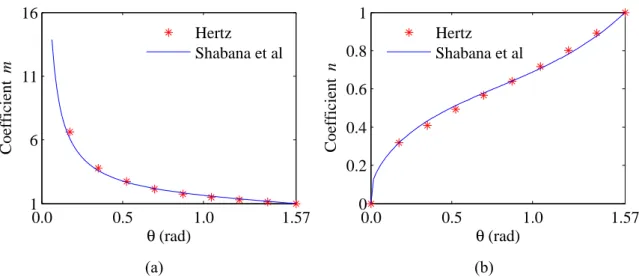
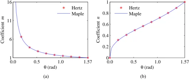
The vehicle-structure interaction methods presented in the second chapter guarantee the equilibrium of the contact forces and the constraint equations but do not take into account the local deformations that arise in the vicinity of the contact region. The formulation proposed in this thesis uses an enhanced node-to-segment contact element, which includes an additional Hertzian spring that relates the contact forces to the local deformations of the contact region. The third chapter discusses the Hertz contact theory, with special focus given to its assumptions and limitations. Hertz provided a few tabulated values to calculate the force-deflection relationship of the contact spring as a function of a parameter that depends only on the geometrical properties of the two contacting bodies. The computer program Maple is used to provide additional tabulated values.
An accurate, efficient and simple formulation for analysing the vehicle-structure interaction, referred to as direct method, is explained in the fourth chapter. At each instant, the equations of motion of the structure and vehicles are complemented with additional constraint equations that relate the nodal displacements of the vehicles to the displacements of the corresponding points of the structure. These equations form a single system that is solved directly. The node-to-segment contact element presented in this chapter does not allow separation and does not take into account the local deformations that arise in the vicinity of the contact region. Some numerical examples to validate the accuracy of the proposed formulation against semi-analytical solutions are provided.
In the fifth chapter, a search algorithm is used to detect which elements are in contact, with the constraints imposed only when contact occurs. Also, an enhanced node-to-segment contact element, which includes an additional Hertzian spring that relates the forces acting at the interface to the local deformations in the vicinity of the contact region, is proposed. Due to the nonlinear nature of the constraint equations and Hertzian spring, an incremental formulation based on the Newton-Raphson method is adopted. The results calculated using the direct method are compared with those obtained with the ANSYS commercial software to validate the accuracy and efficiency of the proposed method.
The numerical modelling and dynamic analysis of the train-track system is explained in the sixth chapter. The KHST is adopted in this work. The ballast and sleepers of the track are modelled with 3D solid elements. A 2D track model is used before and after the 3D track to support the vehicle. The influence of using a 2D rigid or flexible track model, the force-deflection relationship considered for the Hertzian spring and the numerical dissipation provided by the time integration scheme are studied in this chapter. The results calculated using the direct method are validated against those calculated with ANSYS and the efficiency of both approaches is compared.
The dynamic interaction that occurs during the passage of the KHST over the Alverca viaduct, located on the Northern Line of the Portuguese railway network, is analysed and discussed in the seventh chapter. The development of the finite element model of the viaduct is explained in detail. Its geometrical and mechanical properties are calibrated using an FE model updating technique that compares the numerical response of the viaduct with data measured during an ambient vibration test performed by Malveiro et al. (2013). The influence of the track irregularities, ballast instability, local deformations of the slab of the viaduct and force-deflection relationship of the Hertzian spring are analysed in this chapter. The accuracy and efficiency of the direct method proposed in Chapters 4 and 5 are validated by comparing the results calculated using the proposed method and ANSYS.
The final conclusions and suggestions for future research in the field of train-bridge interaction are presented in the eighth chapter.
7
2 OVERVIEW OF VEHICLE-STRUCTURE INTERACTION
METHODS
2.1 INTRODUCTION
The dynamic response of structures subjected to the passage of vehicles has been studied for more than one hundred years. The scientific community has witnessed the proliferation of several studies proposing different vehicle-structure interaction algorithms that lack a detailed comparison with the already existing methods. The main objective of this chapter is to assist the reader in comparing the main advantages and disadvantages of the vehicle-structure interaction methods that are more relevant to the present work.
There are two fundamentally different approaches to evaluating the dynamic behaviour of structures: deterministic and nondeterministic. If the excitation is assumed to be known as a function of time, a deterministic approach is used. On the other hand, if the excitation is a random function described by statistical means, nondeterministic methods have to be used. Also, the dynamic behaviour can be evaluated in the frequency domain or in the time domain. The frequency domain methods require less computational effort but may impose some restrictions when dealing with nonperiodic effects and nonlinear structural models (Popp et al., 1999). There are several nonlinearities that should be considered, such as nonlinear suspensions, nonlinear contact, the state dependent rail pads and ballast properties, and the loss of contact between sleepers and ballast (Nielsen et al., 2003; Nielsen & Oscarsson, 2004). In the present work, only the deterministic approach and time domain methods are adopted.
The dynamic response of structures subjected to the passage of vehicles can be studied using different models: moving loads, moving masses or moving vehicles. Most of the earlier studies aimed to obtain simplified analytical solutions to be used in structural design. The moving load model has been adopted by several researchers (Biggs, 1964; Frýba, 1999) and can be used to analyse systems in which the inertial forces of the vehicle are small when compared with those of the structure, and when the response of the vehicle is not important. Analytical solutions can be obtained for simple cases, allowing a better understanding of the main parameters that influence the response of the system (Goicolea
& Antolin, 2012). When the inertial forces of the vehicle cannot be neglected, the moving mass model is more suitable (Willis, 1849; Biggs, 1964; Ting et al., 1974; Inbanathan & Wieland, 1987; Akin & Mofid, 1989). However, this type of model is also unable to simulate the response of the vehicle and to consider important effects such as bouncing and pitching of the masses of the vehicle and the irregularities at the wheel-rail interface. Therefore, in most cases, the moving vehicle model must be adopted to properly account for the interaction between the two subsystems. A review and comparison of the existing methods for solving the vehicle-structure contact problem is presented in this chapter. Special attention is given to the accuracy, robustness, efficiency and simplicity of the different methods.
The vehicle-structure system can be modelled using finite element or multibody simulation software. Most of the multibody simulation programs use simplified track models that may not adequately take into account the deformations of the track and the bridge. For this reason, the methods based on multibody simulation are not addressed in this work. Diana et al. (2002) studied numerically and experimentally the passenger comfort in railway vehicles and concluded that the accelerations of the carbody significantly depend on its structural flexibility. Therefore, traditional rigid body models that do not account for the flexibility of the vehicle components might not accurately assess the passenger comfort.
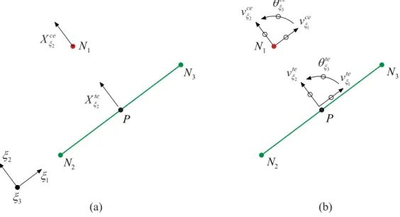
The finite element models can take into account the structural flexibility of all the components of the vehicle-structure system. These models can be defined using two main methodologies: one that formulates the structural matrices for the entire system, i.e., without separating the two subsystems into independent meshes, and another that models the structure and vehicle as two separate subsystems with non-matching meshes. Since most of the contact mechanics literature only addresses methodologies dealing with non-matching meshes, the former methods are not addressed in this work. A description of these methods can be found in Au et al. (2001), Song et al. (2003) and Xia and Zhang (2005). Figure 2.1 shows a general vehicle model moving over a simple structure. The two subsystems are modelled separately and have non-matching meshes. When studying the contact between two bodies, one conventionally has a contact surface and the other a target surface. In this work, it is assumed that the contact surfaces belong to the vehicle and that the structure contains the target surfaces. The displacements of the contact nodes of the
Overview of vehicle-structure interaction methods 9
vehicle and the corresponding points of the target elements of the structure are denoted by
vce and vte. The superscripts ce and te indicate contact and target element, respectively. The displacements of the target elements correspond to auxiliary interior points of the elements and are not degrees of freedom (d.o.f.) of the system.
Figure 2.1 – Schematic illustration of the vehicle-structure system.
This chapter describes three different approaches that model the vehicle and structure separately but deal with the coupling using different techniques: direct equilibrium of contact forces, variational formulations and condensation methods. When the coupling between the vehicle and structure is taken into account by establishing the equilibrium of the contact forces directly and imposing the contact constraint equations, the contact forces are considered explicitly and treated as external forces applied on the right-hand side of the equation of motion (see Section 2.2). The variational formulations described in Section 2.3 take into account the variations of the total energy of the system instead of considering explicitly the inertial, damping and elastic forces. A term is added to the total energy of the system to impose the constraint equations. These methods are well-known in the optimisation theory and contact mechanics and are used by most of the commercial finite element packages to handle contact problems. The approach based on condensation methods is described in Section 2.4 and uses the equations that relate the displacements of the vehicle and structure to condense out all the vehicle d.o.f.
Structure Vehicle ce v te v
2.2 DIRECT EQUILIBRIUM OF CONTACT FORCES
In this approach, the coupling between the vehicle and structure is taken into account by establishing directly the equilibrium of the contact forces and by imposing contact constraint equations. Thus, the contact forces are considered explicitly and treated as external forces in the equation of motion. The equations of motion and the contact constraint equations form a single system of linear equations. Two different types of methods are available for solving this system: the direct method developed by Azevedo et
al. (2007) and Neves (2008), and the iterative methods (Veletsos & Huang, 1970; Hwang & Nowak, 1991; Wang & Huang, 1992; Green & Cebon, 1994; Yang & Fonder, 1996; Delgado & Santos, 1997).
2.2.1 Formulation of the equations of motion
The equations of motion governing the dynamic response of the vehicle-structure system represented in Fig. 2.1 can be expressed as
F
a
K
a
C
a
M
(2.1)where M is the mass matrix, C is the viscous damping matrix, K is the stiffness matrix, F is the load vector and a are the nodal displacements. The dots represent differentiation with respect to time. For the sake of clarity, the formulation presented in this section assumes linear elastic material behaviour, deformation-independent loading and that there is no loss of contact between the vehicle and structure. The nonlinear contact is addressed in Chapter 5.
The load vector can be expressed as
te te ce ce
X
D
X
D
P
F
(2.2)where P corresponds to the externally applied nodal loads, whose values are known, and X are the forces acting at the contact and target elements, whose values are unknown. Each matrix D relates the forces acting at the contact interface to the equivalent nodal loads. According to Newton’s third law, the contact forces acting on the vehicle and structure (see Fig. 2.1) must be of equal magnitude and opposite direction, i.e.,
0
X
Overview of vehicle-structure interaction methods 11
Substituting Eq. (2.3) into Eqs. (2.2) leads to
X
D
P
F
(2.4) where ceX
X
(2.5) te ce D D D (2.6)Substituting Eq. (2.4) into Eq. (2.1) gives
X
D
P
a
K
a
C
a
M
(2.7)2.2.2 Direct integration of the equations of motion
In this chapter, Eq. (2.7) is solved using the Newmark direct integration method. This step-by-step method divides the loading and the response history into a sequence of time steps and employs numerical integration techniques to satisfy the equations of motion at each discrete time interval. This technique assumes a variation of the displacements, velocities and accelerations within each step. The displacements and velocities can be expressed in terms of the accelerations or an alternative relationship can be assumed. In any case, only one unknown vector remains. The assumption made about this variation determines the accuracy, stability and computational cost of the method (Bathe, 1996). For the case of a nonlinear analysis, the procedure discussed in this section may be easily modified into an incremental form. The equations of motion (2.7) at the current time step (t + Δt) are given by t t t t t t t t t t t t
C
a
K
a
P
D
X
a
M
(2.8)In the Newmark method, the velocities and accelerations at the current time step are approximated with (Newmark, 1959; Bathe, 1996)
t t t
t t t t A a a A a A a a 1 4 5 (2.9)
t t t
t t t t A a a A a A a a 0 2 3 (2.10)2 0 β 1t A t β γ A 1 t β A 1 2 (2.11) 1 2 1 3 β A 4 β 1 γ A 1 2 5 β γ t A
The parameters γ and β control the stability and accuracy of the method. Substituting Eqs. (2.9) and (2.10) into Eq. (2.8) and rearranging the terms yields
t t t t t t FD X a K (2.12) where K C M KA0 A1 (2.13) and
t t t
t t t
t t M A a A a A a C A a A a A a P F 0 2 3 1 4 5 (2.14)2.2.3 Contact constraint equations
The constraint equations that guarantee that there is no separation between the contact elements of the vehicle and the target elements of the structure (see Fig. 2.1) are given by
r
v
v
ce
te
(2.15)where r are the irregularities between the contact and target elements. The displacements of the contact nodes and auxiliary points of the target elements are given by
a H vce ce (2.16) a H vte te (2.17) where each transformation matrix H relates the vector of nodal displacements a to the displacements of the contact nodes and auxiliary points of the target elements. Substituting Eqs. (2.16) and (2.17) into Eq. (2.15) leads to
r
a
H
(2.18)Overview of vehicle-structure interaction methods 13 te ce H H H (2.19) 2.2.4 Direct method
Azevedo et al. (2007) and Neves (2008) developed an accurate, efficient and robust algorithm in which the equations of motion of the vehicle and structure are complemented with additional constraint equations that relate the displacements of the contact nodes of the vehicle to the corresponding displacements of the target elements of the structure. These equations form a single system with displacements and contact forces as unknowns. Rewriting Eq. (2.18) for the current time step leads to
t t t t t t H a r (2.20)
Equations (2.12) and (2.20) can be expressed in matrix form leading to the following system of equations t t t t t t t t t t r F X a 0 H D K (2.21) The symmetry of the coefficient matrix can be demonstrated using Betti’s theorem, i.e.,
T
D
H (2.22)
The system of equations (2.21) is solved directly, leading to a robust and accurate algorithm. This becomes even more important for the case of a nonlinear analysis, where convergence is a critical issue. Since some diagonal terms of the coefficient matrix are null, the system is solved using an optimised block factorisation algorithm that takes into account the specific properties of each block, namely, symmetry, positive definiteness and bandwidth. The implementation of the direct method in a finite element computer program is straightforward for the reason that only the contact algorithm needs to be implemented and no additional finite elements have to be developed.
2.2.5 Iterative methods
Classic iterative methods for solving a system of linear equations date to the late eighteenth century (Burden & Faires, 1997). In order to solve a linear system of the form A x = b using iterative techniques, the matrix A can be decomposed into
N M
A (2.23)
The iterative technique starts with an initial vector x0 and generates a sequence of
approximate solution vectors by computing
b x N x
M i1 i (2.24)
where i is the iteration counter. This sequence converges to the unique solution if and only if
M1N
1
(2.25)in which ρ is the spectral radius (Burden & Faires, 1997). A lower spectral radius leads to a faster convergence.
Iterative techniques were first applied to vehicle-structure interaction problems by Veletsos and Huang (1970) and since then have been used by Hwang and Nowak (1991), Wang and Huang (1992), Green and Cebon (1994), Yang and Fonder (1996), Delgado and Santos (1997), Zhang et al. (2008), Ribeiro (2012) and Liu et al. (2014). In order to define the different steps involved in an iterative procedure, it is necessary to partition the system of linear equations (2.21) into the form
t t X X I I t t X t t X t t I t t I t t XX t t I X t t I X t t XX XX I X I X t t X I X I I I I I t t X I X I I I I I r F F F X a a a 0 H H H D K K K D K K K D K K K ~ ˆ ~ ˆ ~ ˆ ~ ˆ ~ ~ ~ ~ ˆ ~ ˆ ˆ ~ ˆ ˆˆ (2.26)
according to the classification of d.o.f. presented in Table 2.1. Table 2.1 – Classification of degrees of freedom.
Type Description
Iˆ free d.o.f. of the structure I~ free d.o.f. of the vehicles X contact d.o.f. of the vehicles
Since the meshes of the vehicle and structure are independent, KI ~ˆI , KIˆX, KI ˆ~I and I
Xˆ
K are null matrices. Also, since the contact forces are assumed to be applied along the X type d.o.f. of the vehicle, t t
XX D and t t XX
H are identity matrices. Therefore, Eq. (2.26) can be written as
Overview of vehicle-structure interaction methods 15 t t X X I I t t X t t X t t I t t I XX t t I X XX XX I X X I I I t t X I I I r F F F X a a a 0 I 0 H I K K 0 0 K K 0 D 0 0 K ~ ˆ ~ ˆ ˆ ~ ~ ~ ~ ˆ ˆˆ (2.27)
Wang and Huang (1992) apply the Gauss-Seidel iterative method to solve this system of linear equations. Before applying this iterative technique, the rows and columns of Eq. (2.27) are reordered to obtain
I X I t t X t t I t t X t t I t t X I I t t X I XX I X XX I I X I t t I X XX ˆ ~ ˆ ~ ˆˆ ˆ ~ ~ ~ ~ ˆ F F F r a X a a K D 0 0 0 I K K 0 0 K K H 0 0 I (2.28)
In the Gauss-Seidel iterative method, the decomposition described in Eq. (2.23) is given by D L M (2.29) U N (2.30)
where D is the diagonal matrix whose diagonal entries are those of A, and L and U are the strictly lower and upper triangular parts of A, respectively. Although iterative techniques have been applied to vehicle-structure interaction problems for more than four decades, there is little information in the literature concerning their convergence characteristics. Green and Cebon (1994) report some convergence problems for the case of vehicles with large wheel forces with frequency content higher than 10 Hz. Yang and Fonder (1996) provide some useful information about the convergence characteristics of the iterative methods proposed in their work but are mainly focused on the number of iterations necessary to achieve convergence. In the present work, the convergence of the iterative methods can be verified more accurately and reliably using the inequality (2.25). Hence, it is easier to identify which blocks of the coefficient matrix of Eq. (2.28) might lead to a slow convergence or even divergence.
I X I t t X i t t I t t I X i t t I i t t X i t t I i t t X I I t t X I XX I X XX I I X I XX ˆ ~ , ˆ ˆ 1 , ˆ 1 , 1 , ~ 1 , ˆˆ ˆ ~ ~ ~ ~ F F F r 0 0 0 a H a X a a K D 0 0 0 I K K 0 0 K K 0 0 0 I (2.31)
Hence, each iteration i+1 consists of the following steps:
1) Calculate the displacements of the contact nodes of the vehicle
i t t I t t I X t t X i t t X,1r Hˆ aˆ, a (2.32)
where the vector t ti I
, ˆ
a contains the nodal displacements of the structure calculated in the previous iteration. In the first iteration of each time step, the displacements
i t t I , ˆ
a are equal to those calculated in the previous time step. 2) Calculate the free nodal displacements of the vehicle
1 , ~ ~ 1 , ~ ~ ~I tIti I IX tXti I a F K a K (2.33)
3) Calculate the contact forces
1 , 1 , ~ ~ 1 , t ti X XX i t t I I X X i t t X F K a K a X (2.34)
4) Calculate the free nodal displacements of the structure 1 , ˆ ˆ 1 , ˆ ˆˆ I tIXt tXti i t t I I I a F D X K (2.35)
5) Check the convergence criterion
1 , ˆ , ˆ 1 , ˆ i t t I i t t I i t t I a a a (2.36) where ε is a specified tolerance. A tolerance between 10-8 and 10-5 is usually
sufficient to obtain an accurate solution (Yang & Fonder, 1996). If the desired degree of convergence is achieved, the procedure may proceed to the next time step, otherwise the iteration counter is incremented and the iterative process continues to step 1).
Overview of vehicle-structure interaction methods 17
Unlike the direct method, the iterative method does not treat the contact forces as unknowns of the system of linear equations. These variables are calculated using Eq. (2.34).
Yang and Fonder (1996) proposed an iterative procedure that uses under-relaxation or Aitken acceleration techniques to improve the convergence characteristics of the method. Under-relaxation methods can be used to obtain convergence of some systems that are not convergent when using the Gauss-Seidel method.
2.2.6 Numerical example
A simple numerical example consisting of a beam clamped at both ends with a concentrated load applied at midspan is shown in Fig. 2.2a. The main objective is to evaluate the convergence of the Gauss-Seidel iterative method independently of the application rather than to evaluate the convergence of the method when used to solve vehicle-structure interaction problems. The Young’s modulus E is equal to 200 GPa and the cross-sectional areas of the left and right beams are 4 and 1 cm2, respectively. The
initial structure is divided into two separate structures in order to analyse the interaction between both parts (see Fig. 2.2b).
(a) (b)
Figure 2.2 – Beam clamped at both ends: a) as a single structure and b) as two separate structures. In order to use the expressions presented in Section 2.2.5 for the analysis of the vehicle-structure interaction, it will be assumed that the left and right beams correspond to the structure and vehicle, respectively. The use of Eq. (2.27) to define the equilibrium and contact constraint equations of the system leads to
0 0 1 1 1 0 1 0 ˆ ˆ ˆ X I X I X I F F X a a k k (2.37)
where FIˆ =
F
X = 100 kN. Calculating the stiffness coefficients using Hooke’s law yields200 kN 100 kN 100 kN
N/m 10 2 N/m 10 8 7 7 ˆ X I k k (2.38) Solving the system of linear equations (2.37) directly results in
kN 60 mm 2 mm 2 ˆ X a a X I (2.39) In order to solve the interaction problem using the Gauss-Seidel iterative method, the equilibrium and contact constraint equations are now defined using Eq. (2.28), leading to
I X I X I X F F a X a k k ˆ ˆ ˆ 0 1 0 0 1 1 0 1 (2.40)
According to Eqs. (2.25), (2.29) and (2.30), since the spectral radius of
M
1N
is equal to 0.25, the iterative process converges to the exact solution. Substituting Eqs. (2.40), (2.29) and (2.30) into Eq. (2.24) leads to I X i I i I i i X I X F F a a X a k k ˆ ˆ 1 ˆ 1 1 ˆ 0 0 0 1 0 0 1 0 0 1 (2.41)
The sequence of approximations of aIˆ,
a
X and X obtained using aI0ˆ 0 and Eq. (2.41) are plotted in Fig. 2.3. A tolerance of 10-5 is used for checking the convergence criteriondefined by Eq. (2.36). This tolerance is satisfied after ten iterations and the values obtained using Eq. (2.36) are plotted in Fig. 2.4.
Figure 2.3 – Sequence of approximate solutions.
0 5 10 0 0.5 1 1.5 2 2.5 3 Iteration 0 5 10 0 0.5 1 1.5 2 2.5 3 Iteration 0 5 10 −100 −80 −60 −40 −20 0 Iteration ˆ (m m ) I a X (k N ) (m m ) X a
Overview of vehicle-structure interaction methods 19
Figure 2.4 – Values of the convergence parameter.
The convergence of the iterative process depends on how the rows and columns of Eq. (2.27) are reordered. To verify this assumption a different reordering is performed resulting in X I X I X I F F a X a k k ˆ ˆ ˆ 0 1 0 0 1 1 0 1 (2.42)
According to Eqs. (2.25), (2.29) and (2.30), since the spectral radius of
M
1N
is equal to 4, the iterative process does not converge. Substituting Eqs. (2.42), (2.29) and (2.30) into Eq. (2.24) leads to X I i X i X i i I X I F F a a X a k k ˆ 1 1 1 ˆ ˆ 0 0 0 1 0 0 1 0 0 1 (2.43)
The sequence of approximations of aIˆ,
a
X and X obtained using a0X 0 and Eq. (2.43)are plotted in Fig. 2.5.
0 2 4 6 8 10 0 0.2 0.4 0.6 0.8 1 Iteration Convergence parameter
Figure 2.5 – Sequence of approximate solution vectors.
It can be concluded that even for a very simple system of linear equations the iterative techniques might diverge if an inadequate permutation of rows and columns is chosen. The numerical example presented here is not a typical vehicle-structure interaction problem. When the iterative methods are applied to these problems, the permutation of rows and columns used takes into account the specific properties of the structure and vehicle, which usually leads to a convergent procedure. Nevertheless, there is little information in the literature concerning the convergence characteristics of iterative methods when used in the analysis of the dynamic vehicle–structure interaction, and so special care must be taken when using this type of procedures.
2.3 VARIATIONAL FORMULATIONS
The equations of motion of any dynamic system can be established using scalar quantities in a variational form known as the Hamilton's principle (Clough & Penzien, 1993). This formulation takes into account the variations of the kinetic and potential energy terms instead of considering explicitly the inertial and elastic forces. There are several formulations available to incorporate the contact constraints into the variational formulation such as the Lagrange multiplier method, the penalty method and the augmented Lagrangian method, among others. The augmented Lagrangian method combines the Lagrange multiplier and penalty methods. These methods are well-known in the optimisation theory and contact mechanics and are used by most of the commercial finite element packages to handle contact problems. A term is added to the total energy of
0 5 10 −2 0 2 4 6x 10 5 Iteration 0 5 10 −2.5 −2 −1.5 −1 −0.5 0 0.5 1x 10 6 Iteration 0 5 10 −5 −4 −3 −2 −1 0 1 2x 10 7 Iteration ˆ (m m ) I a X (k N ) (m m ) X a