www.ccarevista.ufc.br ISSN 1806-6690
Application of
Moiré
technique on strain analysis in farm machinery
elements
1Aplicação da técnica de
Moiré
na análise de deformação em elementos de máquinas
agrícolas
Kelen Cristiane Cardoso2*, Jonathan Gazzola2 e Inacio Maria Dal Fabbro2
ABSTRACT -Development and optimization of projects for agricultural machinery involve the analysis of stress and strain. Moiré photomechanical techniques provide a complete displacement field of the specimen under test, and can aid in understanding the mechanical behavior of parts with complex geometry. Hybrid methods combine fringe patterns of displacement with distribution maps of stress and strain through concepts of the theory of elasticity. The objective of this work was to analyse the use of the shadow moiré technique in the qualitative determination of stress and strain distribution in geometrically complex machine elements. The results were compared with those from an electrical extensometer and a computer simulation. The results demonstrated that the shadow moire technique was quite reliable in analysing the mechanical behavior of geometrically complex machine elements.
Key words:Photomechanical techniques. Hybrid methods. Shadow moiré.
RESUMO - Desenvolvimento e otimização de projetos de máquinas agrícolas envolvem a análise de tensão e deformação. Técnicas fotomecânicas demoiré fornecem campo de deslocamento completo do corpo de prova e podem
auxiliar no entendimento do comportamento mecânico de peças com geometria complexa. Métodos híbridos associam franjas padrões de deslocamento com mapas de distribuição de tensão e deformação, através de conceitos de teoria da elasticidade. O objetivo deste trabalho foi analisar o uso da técnica demoiré de sombra para determinação qualitativa de
distribuição de tensão e deformação em elementos de máquinas de geometria complexa. Os resultados foram comparados com o método de extensometria elétrica e por simulação computacional. Os resultados mostraram que a técnica demoiré de
sombra foi bastante confiável para analisar o comportamento mecânico de elementos de máquinas de geometria complexa.
Palavra-chave: Máquinas Agrícolas. Técnicas Fotomecânicas.Moiré de sombra.
*Autor para correspondência
1Recebido para publicação em 19/04/2013; aprovado em 23/03/2014
Parte da Dissertação de Mestrado do primeiro autor apresentada ao curso de Pós-Graduação em Máquinas Agrícolas/Engenharia Agrícola da Universidade Estadual de Campinas
2Faculdade de Engenharia Agrícola, Universidade Estadual de Campinas, Campinas-SP, Brasil, 13.083-875, [email protected],
INTRODUCTION
In agricultural science, mainly in farm machinery design and development, the association of stress and strain analysis to product optimization is of very common occurrence. Accurate analyses are based on isolated element tests through experimental techniques (MAZZETI FILHO
et al., 2004). Strain-gage techniques generate point to
point deformation and displacement data, requiring many sensors conveniently positioned which demands time and cost increase (RI; FUJIGAKI; MORIMOTO, 2010).
Mechanical components shapes are very commonly surveyed by means of optical techniques which can be associated to interferometry to generate solutions to problems involving static or dynamic situations (GOMESet al., 2009). Optical methods are usually named
photomechanical techniques which are able to generate complete displacement field (ANDONIAN, 2008) being recognized as stress analysis experimental methods (LEI
et al., 2007). Stress field can also be determined by means
of hybrid methods which associate optical techniques with the theory of elasticity (DOYLE, 2008).
Moiré techniques are include in the photomechanical
category which are based on optical interferometry, which yield excellent results in determining displacement field, however it requires adequate fringes spatial differentiation to generate stress and deformation fields. The advantages of moiré methods are associated to low cost of required
equipment, low sensitivity to external noise, fast trials as well as and applicability to large displacement determination (DOYLE, 2008; GLEICEet al., 2011; RYUet al., 2008).
The moiré phenomenon takes place when two
optical grids of certain density are superposed at a specific angle; fringes are generated with different period and angle of the two initial screens (LINO; DAL FABBRO, 2004). The third group of strips is denominated asmoiré fringes
which vary from dark color when generated by destructive interfering waves to totally clear color if generated by constructive interfering waves (BERALDOet al., 2007).
Moiré fringes can be generated by means of the
shadow moiréor by the projection moiré method (PORTO;
GURGEL; FARINATTI, 2011). In shadowmoiré method,
the grid is positioned in front of the testing body and illuminated by a light source, projecting the grid shade
followed by the deformation and stress field (BASTOS; TAVARES, 2004).
The pertinent literature discloses several research reports on the application ofmoiré methods to determine
the qualitative stress state on bodies of simple geometry. Mazzeti Filhoet al. (2004) report the application of amoiré
method to determine the displacement field on rubber discs models. Albieroet al. (2012) determined points of
isodeformation on nuts shell surface. Gazzolaet al. (2012)
report qualitative determinations of stress distribution of wood beams under flexural loading.
The objective of this research work was to analyze the application of shadowmoiré method to a qualitative
determination of deformation and stress distribution on farm machinery elements of complex geometry.
MATERIALS AND METHODS
Photomechanical tests were carried out in the Laboratory of Optics of the Faculty of Agricultural Engineering at the State University of Campinas, in Campinas, SP, Brazil. A diaphragm spring taken from a tractor clutch was selected as testing body for exhibiting discontinuous as well as complex geometry associated to a working condition characterized by axial loading yielding out of plane displacement. Shadow moiré
Figure 2 - Experimental setup for the diaphragm spring loading tests
Figure 3 -(a) Experimental setup for shadowmoiré tests and (b) equipment positioning
The experimental setup for the moiré
photomechanical tests included a Ronchi optical grid with a period of 0.2 mm, a SONY multimedia projector and a SAMSUNG digital camera of 6.1 Mega Pixels with remote control to prevent undesirable movement to capture images. Testing boby was painted with opaque White color to improve pattern fringes contrast. The optical grid was positioned in front of the testing body, as showed on Figure 3 (a) which details themoiré
experimental setup. Figure 3 (b) exhibits the equipment positions during experimental trials.
It has been applied seven different force levels on the top of the diaphragm membrane generating up to 7 mm of axial displacement on the elements. First image was generated of non-deformed body following, one image at each mm of element displacement, generating a group of 8 images to be processed.
Image processing included the application of the IDRISI KILIMANJARO and ImageJ software which was divided into two steps, as it will be described as follows (GAZZOLA et al., 2010). In the first step a
common processing was carried to all the images by means of the ImageJ software in order to remove the background from the testing body image, noise as well as filter application to improve fringes contrast as recommended by KUNINARIet al. (2008).
In the second step the isochromatic fringes map has been generated by means the IDRISI KILIMANJARO software, through the Whole field Subtraction Technique as described by Albiero et al.
(2012) which is based on the pixel to pixel subtraction of na image generated at a Xi loading level from an image generated at Xi+1 loading level. That method is employed to determine the undergoing deformation of a testing body between two different loading levels.
Following, the isochromatic fringes were identified from the pattern moiré fringes by means
RESULTS AND DISCUSSIONS
Table 1 - Pixel light intensity as generaterd by the IDRISI KILIMANJARO software
Figure 6, Figure 7, Figure 8 and Figure 9 shows the pixel intensity variation graph for each applied displacement.
The graphs show that the total pixel intensity variation presented linear behavior close to an average R2 value of 96% according to element deformation, i.e.,
when the diaphragm membrane is axially loaded which
Figure 4 - Strain gages positions on the diaphragm spring elements
Figure 5 - Isodeformation map generated by the IDRISI KILIMANJARO software
Displacement Trial 1 Trial 2 Trial 3 Trial 4
1 mm 116 166 201 165
2 mm 138 199 209 197
3 mm 154 217 226 214
4 mm 176 240 224 233
5 mm 190 251 239 249
6 mm 204 261 254 258
7 mm 216 265 267 268
concentration point (GAZZOLA et al., 2012). In
order to compare as well as to validate the results generated by the moiré technique a finite element
model was tested through the Abaqus 6.10 software. The simulation was carried on diaphragm spring element model holding the same dimensions as the real ones, where the virtual environment held the same load application conditions including imposed displacement and boundary conditions.
Figure 6 - Pixel intensity variation versus diaphragm element displacement graph for the trial 1
Figure 7 - Pixel intensity variation versus diaphragm element displacement graph for the trial 2
Figure 8 - Pixel intensity variation versus diaphragm element displacement graph for the trial 3
Figure 9 - Pixel intensity variation versus diaphragm element displacement graph for the trial 4
stress distribution covered the entire diaphragm surface, with visible fringes concentration. High concentration of lines clearly indicates stress concentration. Such fringes behavior indicates stress concentration evolution on the testing body due to the increasing loading. The fringe
color intensity variation is associated to the imposed displacement variation, where the lowest displacement which is associated to the lowest stress is indicated predominantly by red color which progressively reaches the yellow color corresponding to the maximum imposed displacement of 7 mm which is, in turn, associated to the maximum stress. By comparing fringe distances it can be noted that the diaphragm elements located at the upper right side exhibits higher stress concentration at the borders and as the displacement increases, elements located at the bottom left side will show similar behavior. That fact indicates that the deformation rate of the diaphragm element is different.
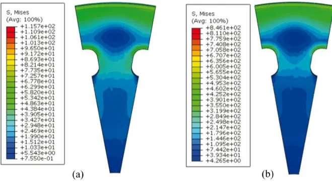
Figure 11 shows stress evolution result on a diaphragm element generated by computer simulation for displacement variation from 1 mm to 7 mm.
By analyzing Figure 11 it can be noted that the computer simulation indicates the higher stress concentration at the lateral region of the diaphragm spring, mainly at element basis as well as at diaphragm border. The central area of the diaphragm showed low stress concentration for the imposed displacement of 1 mm, mainly between the diaphragm border and the element basis, where the stress values were close to zero. The imposed displacement of 7 mm did not show qualitative differences on the stress distribution map when compared with the displacement of 1 mm, however the stress module was amplified. As the computer simulation map did not show qualitative differences on the stress distribution, remaining results were omitted, emphasizing that the stress modules are variables ranging from the maximum and minimum displacement.
Figure 12 compares the qualitative stress distribution as generated by themoiré method and the
side, moiré technique indicated concentration at the
elements lateral areas where the analysis reveals high
Figure 10 -Isochromatic lines map associated to displacement of (a) 1 mm, (b) 2 mm, (c) 3 mm, (d) 4 mm, (e) 5mm, (f) 6 mm, (g) 7 mm, and (h) color scale associated to pixel intensities as generated by the ImageJ software
Figure 11 -Stress distribution maps as generated by the Abaqus software for displacements of (a) 1mm and (b) 7 mm
Figure 12 -Comparisson of the stress distribution results generated by the moiré method and the computer simulation for
displacement imposition of (a) 2 mm, (b) 4 mm and (c) 7 mm
However, such a geometrical differentiation generates certain variations on the stress distribution during loading. That hypothesis was verified by means of the extensometric technique.
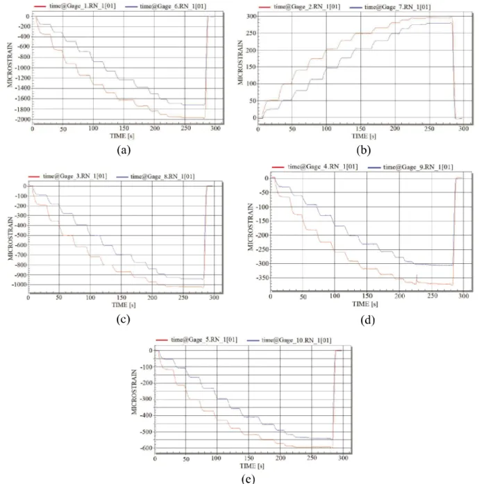
Figure 13 shows the results yielded by means of the extensometric technique.
Results obtained as shown on the graph indicate that at each displacement applied on the testing body, an irregular deformation increment, i.e., the elements showed, each one, different deformation rates.
The graph displayed on figure 13 indicate that the resulting stress generated by extensometry show similar qualitative behavior as the deformation variation between the elements when generated by the moiré
method. This confirms that the stress and deformation variation between elements of a diaphragm spring is a recurrent situation and it must be considered in designs.
Generaly speaking, resulting stress distribution generated by the moiré method indicates that stress
Figure 13 -Strain gage graph output respectively for the positions (a) 1 and 6, (b) 2 and (7), (c) 3 and 8, (d) 4 and 9, (e) 5 and 10
also revealed stress concentration at the element border as well as at the element basis. The element displacement increased with the stress module. Stress distribution
continuity as well as regularity , which are not assumed by the extensometry, nor by themoiré method. In other
words, moiré and extensometry assume the body to
exhibit real behavior.
The absence of variation on elements deformation results indicated by computational simulation has been occurred because this technique analyzes parts characterized to be isotropic, homogeneous, continuous and unique geometry between elements. But, moiré
and extensometric techniques, which demonstrated such variations, results have been generated on testing body with geometry variation between elements and material irregularities.
CONCLUSION
Based on what it has been explained before, it can be concluded that the shadow moiré technique
can be considered as a profile measuring method of mechanical analysis which can generate reliable results in determining qualitative stress distribution on machine elements of complex geometry. Results generated by the shadowmoiré method corresponded to the expected
results as obtained by extensometry. The simplicity showed by the above referred method turn it attractive to the experimental mechanics study as well as to industrial applications. Stress and deformation quantification studies are recommended for future studies.
REFERENCES
ALBIERO, D.et al. Moiré Optical Technique For Evaluation
Of Cashew Nuts (Anacardium Occidentale, L.) Isostrain.
Varia Scientia Agrarias, v. 2, n. 2, p. 9-20, 2012.
ANDONIAN, A. A. T.Optical Methods. Springer Handbook of Solid Mechanics. New York: Sharpe, 2008. p. 823-837. BASTOS, L. F.; TAVARES, J. M. R. S. Um sistema de ferramentas de processamento e análise de imagens demoiré:
apresentação. In: ENCONTRO NACIONAL DE ANÁLISE
DE TENSÕES E MECÂNICA EXPERIMENTAL, 5., 2004, Coimbra.Anais... Coimbra: APAET, 2004.
BERALDO, A. L.et al. Técnica demoiré aplicada al análisis
de esfuerzos de compresión en el bambu guadua. Maderas: Ciencia y Tecnologia Concepción, v. 9, n. 3, p. 309-322, 2007. BRAGA, R. A.et al. Supression of border effects in moiré
techniques using three-dimensional methods. Biosystems Engineering, v. 102, n. 1, p. 1-8, 2009.
COSTA, R. M. et al. Sensitivity of the moiré technique for measuring biological surfaces.Byosistem Engineering, v. 100, n. 3, p. 321-328, 2008.
DOYLE, J. F.Hybrid Methods. Springer Handbook of Solid Mechanics. New York: Sharpe, 2008.
GAZZOLA, J. et al. Shadow Moiré Applied to Torsional
Stress Distribution Mapping. Agricultural Engineering Journal, v. 48, n. 2, p. 61-65, 2010.
GAZZOLA, J.et al. Photomechanical analysis of wooden testing
bodies under flexural loadings. World Academy of Science, Engineering and Technology, v. 70, p. 396-401, 2012. GOMES, T. S. et al. Calibração da técnica demoiré aplicada
a perfilometria de protótipos mecânicos. Revistas Ciência e Agrotecnologia, v. 33, n. 2, p. 574-579, 2009.
GLEICE, C. A. et al. Recuperação de Topografia de Ovos por Meio da Técnica de Moiré e Calibração Independente.
Engenharia Agrícola. v. 31, n. 2, p. 211-218, 2011.
KUNINARI, F.et al.Moiré aided soil-tractor tire contact area and contact volume determination. Journal of Agricultural Machinery Science, v. 4, n. 1, p. 39-43, 2008.
LEI, Z.; YUN, H.; YUN, D.; KANG, Y. Numerical analysis of phase-stepping interferometric photoelasticity for plane stress separation. Optics ans Laser in Engineering, v. 45, n. 1, p. 77-82, 2007.
LINO, A. C. L.; DAL FABBRO, I. M. Determinação da topografia de uma fruta pelas técnicas de moiré de sombra com multiplicação de franjas.Revista Ciência Agrotécnica. v. 28, n. 1, p. 119-125, 2004.
MAZZETI FILHO, V.et al. Application of aMoiré technique in the stress distribution mapping of circular rotors. Revista Ciência e Tecnologia, ano 7, n. 10, p. 31-34, 2004.
PORTO, F.; GURGEL, J. L.; FARINATTI, P, T, V. Topografia de Moiré como Método de Avaliação Postural: Revisão
do Estado da Arte. Revista Brasileira de Geriatria e Gerontologia, v. 3, n. 14, p. 567-577, 2011.
RI, S.; FUJIGAKI, M.; MORIMOTO, Y. SamplingMoiré Method
for Accurate Small Deformation Distribution Measurement. Experimental Mechanics. v. 50, n. 4, p. 501-508, 2010. RYU, W. et al. A Study on the 3-D Measurement by Using
Digital Projection Moiré Method. Optik - International Journal for Light and Eletron Optics. v. 119, n. 10, p. 453-458, 2008.
SPINELLI, H. A.; SILVA, F. A. Aplicação da Fotoelasticidade na Análise Estrutural de uma Junta Rebitada de Uso Aeronáutico. 2003, Guaratinguetá.Anais... Guaratinguetá, 2003.
XIAO, X. et al. Displacement and Strain Measurement by