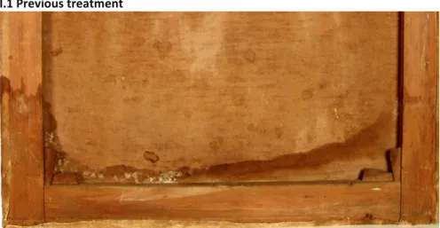
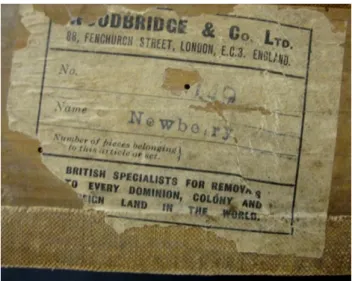
Treatment of a nineteenth century male portrait in oil including the characterisation of materials, technique and a study of the lead soap aggregation in the paint composite
Texto
Imagem
Documentos relacionados
The probability of attending school four our group of interest in this region increased by 6.5 percentage points after the expansion of the Bolsa Família program in 2007 and
Remelted zone of the probes after treatment with current intensity of arc plasma – 100 A, lower bainite, retained austenite and secondary cementite.. Because the secondary
Neste trabalho o objetivo central foi a ampliação e adequação do procedimento e programa computacional baseado no programa comercial MSC.PATRAN, para a geração automática de modelos
Ousasse apontar algumas hipóteses para a solução desse problema público a partir do exposto dos autores usados como base para fundamentação teórica, da análise dos dados
didático e resolva as listas de exercícios (disponíveis no Classroom) referentes às obras de Carlos Drummond de Andrade, João Guimarães Rosa, Machado de Assis,
Os modelos desenvolvidos por Kable & Jeffcry (19RO), Skilakakis (1981) c Milgroom & Fry (19RR), ('onfirmam o resultado obtido, visto que, quanto maior a cfiráda do
Managers involved residents in the process of creating the new image of the city of Porto: It is clear that the participation of a resident designer in Porto gave a
The fourth generation of sinkholes is connected with the older Đulin ponor-Medvedica cave system and collects the water which appears deeper in the cave as permanent
