Outubro, 2016
Shayan Khalili
Licenciado em BioquímicaBiocatalytic Fibers For Bioremediation
Dissertação para obtenção do Grau de Mestre em Bioquímica
Orientador: Prof. Doutora Susana Filipe Barreiros, FCT-UNL Co-orientadores: Prof. Doutor João Paulo Borges, FCT-UNL
Júri:
Presidente: Prof. Doutor José Ricardo Ramos Tavares
Arguentes: Doutora Ana Catarina Bernardino Baptista
Vgais:Prof. Doutora Susana Filipe Barreiros, FCT-UNL Prof. Doutor João Paulo Borges, FCT-UNL
[Biocatalytic Fibers For Bioremediation ]
Copyright © [Nome completo do autor], Faculdade de Ciências e Tecnologia, Universidade Nova de Lisboa.
A Faculdade de Ciências e Tecnologia e a Universidade Nova de Lisboa têm o direito, perpétuo e sem limites geográficos, de arquivar e publicar esta disserta-ção através de exemplares impressos reproduzidos em papel ou de forma digi-tal, ou por qualquer outro meio conhecido ou que venha a ser inventado, e de a divulgar através de repositórios científicos e de admitir a sua cópia e distribui-ção com objectivos educacionais ou de investigadistribui-ção, não comerciais, desde que seja dado crédito ao autor e editor.
v
“When you see a good move, look for a better one.
”iii
Agradecimentos
“ We can know only that we know nothing, and that is the highest degree of human wisdom.”
“By, leo Tolstoy “
Depois deste ano intenso, se há algo que ficou bem claro para mim, é que a autocorreção é uma ferramenta bastante forte que devemos usar ao longo da nossa carreira.
Notei que muitas vezes me sentia embaraçado com dúvidas e erros, mas percebi que nada faria efeito se não tomasse percepção das minhas próprias limitações e do que fazer para as ultrapassar. Tal não seria possivel sem o apoio de muitos que me acompanharam neste percurso.
Começo por agradecer à Professora Susana Barreiros, por não ser apenas uma orienta-dora, mas sim, por ter sido um grande apoio para mim e para todas as pessoas que a rodei-am, e assim fazer com que pudesse integrar-me perfeitamente no seu laboratório. Fico a de-ver-lhe todo o conhecimento que me transmitiu e toda paciência e confiança que depositou em mim.
São poucas as palavras para descrever o meu agradecimento ao Professor João Paulo, uma das pessoas mais sinceras e humildes entre outras qualidades inexplicáveis que tem. Obrigado por todo tempo que disponibilizou na co-orientação desta tese e por todas as fer-ramentas que me disponibilizou para que o trabalho pudesse decorrer ao longo do tempo.
Deixo um forte agradecimento ao Gustavo que sempre apoiou na parte prática e, claro, ao Alexandre, à Rita, à Francisca e ao Bruno que me orientaram no laboratório e foram exce-lentes professores e colegas de trabalho e fizeram fluir o trabalho e partilharam o seu conhe-cimento.
Tendo trabalhado em dois laboratórios, fez com que pudesse alcançar mais amizades e colegas de trabalho fantásticos como o Jaime e a Inês e os restantes colegas do departamento de matérias. Foram bastante atenciosos e ótimas pessoas para mim e tiveram paciência para as muitas questões que coloquei.
Agradeço também aos ajudantes dos dois laboratórios que se mostraram sempre dis-poníveis.
Aos meus amigos Luís Fernandes, Inês Filipa, Pedro Prior, André Oliveira, Ricardo Sagreiro, e a tantos outros que se os enumerasse a todos nao acabaria estes agradecimentos. Um forte abraço de gratidão por ter pessoas como vocês na minha vida, por me terem apoi-ado, nos momentos altos e baixos, tanto nos assuntos relacionados com a tese como nos as-suntos pessoais.
Por fim, quero agradecer aos meus Pais que, para mim, são o exemplo de ser humanos excepcional. Mesmo estando a muitos quilómetros de Portugal sempre me apoiaram e esti-veram presentes para mim. E ao meu Irmão que é a pessoa que mais amo, por me dar forças
iv para nunca desistir, por valorizar a pessoa que sou e por ser a minha motivação para lhe ser um bom exemplo. É a vocês que dedico esta dissertação.
iii
Resumo
As enzimas podem exibir excelentes propriedades catalíticas, nomeada-mente alta atividade em condições ambientais variadas, alta especificidade e seletividade. Apesar destes aspectos positivos, demonstram algumas limitações que podem inibir a sua aplicação a nível industrial. A imobilização de enzimas em fibras poderá proporcionar aos materiais catalíticos obtidos boas proprieda-des mecânicas, uma elevada área superficial, resistência à temperatura, alcalói-des e humidade.
Este trabalho consiste na produção, através da técnica de electrospinning, de membranas biocatalíticas contendo uma lacase, para biorermediação enzi-mática por esta enzima.
O plano de trabalho inicial consistia na produção de fibras coaxiais, com uma camada exterior de sílica, conferindo resistência e protecção, e um núcleo constituído por uma gelatina iónica, resultante do cross-linking entre gelatina e um líquido iónico, contendo a lacase. Para a preparação das camadas de sílica, seleccionou-se o processo sol-gel, utilizando como percursores tetrametoxisila-no (TMOS) ou tetraetoxisilatetrametoxisila-no (TEOS), mediante catálise ácida com HCl e utili-zação de metanol como co-solvente. Para conferir porosidade e flexibilidade à estrutura de sílica, adicionou-se solução de álcool polivinílico (PVA) à solução de electrospinning, que foi testada na produção de fibras. Entre as várias for-mulações testadas, a formulação (em razões molares) 1:1,8:1.1:7,9E-03 TMOS:H2O:metanol:HCl conduziu a fibras de aspecto regular e com baixa dis-persão de tamanhos, tal como revelado por microscopia electrónica de varri-mento. Igualmente com vista à preparação de fibras co-axiais, testaram-se for-mulações para o núcleo das fibras. O controle de temperatura disponível não permitiu impedir que a solução de gelatina de porco e líquido iónico dihidro-genofosfato de colina solidificasse na agulha, inviabilizando o processo de elec-trospinning. Para ultrapassar esta dificuldade, foi feita uma diminuição da con-centração de gelatina, que resultou na produção de electrospray, em vez de fi-bras. De seguida foi feita uma alteração na natureza da gelatina, que foi substi-tuída por gelatina de peixe, cuja dissolução ocorre à temperatura ambiente. No entanto, o cross-linking desta gelatina com o líquido iónico não foi eficiente, e a membrana de fibras à base de gelatina obtida dissolvia-se imediatamente em água.
Optou-se então por produzir uma membrana em camadas, constituída nomeadamente por uma camada de fibras à base de sílica em cada uma das su-perfícies, e uma zona interior compreendendo fibras reactivas à base de um
po-iv límero diferente da gelatina. Tando já sido feita a optimização da produção de fibras de sílica pelo processo sol-gel, o foco foi agora a produção das fibras bior-reactivas do interior da membrana. Testaram-se dois polímeros, nomeadamente policaprolactona (PCL) e PVA. No sentido da preservação da actividade enzi-mática, testaram-se solventes diferentes para a PCL, mas em nenhum dos casos se obteve evidência de actividade da lacase imobilizada nas fibras obtidas. Já nas fibras à base de PVA, a enzima manteve-se activa. Procedeu-se então à pro-dução de membranas de fibras com camadas superficias de sílica e interior de PVA com enzima. Estas membranas exibiram actividade catalítica, permitindo cumprir o objectivo do trabalho.
Palavras chave: Electrospinning, sílica, fibras biocatalíticas, PVA, lacase,
v
Abstract
Enzymes can exhibit excellent catalytic properties, namely high activity at different environmental conditions, high specificity and selectivity. Despite these advantages, they exhibit some limitations that can hinder their application in industry. The immobilization of enzymes on fibers can lend good mechanical properties, high surface area, and resistance against high temperature, alkaloids and humidity to the resulting catalytic materials.
This work consists in the production, using electrospinning, of biocata-lytic membranes containing laccase with a view to enzymatic bioremediation.
The initial work plan consisted in the production of coaxial fibers with an outer layer of silica, lending strength and protection, and a core containing an ionic gelatin resulting from the cross-linking of gelatin and an ionic liquid, containing the laccase. For the preparation of silica layers, it was selected the sol-gel process using as precursors tetrametoxysilane (TMOS) or tetraethox-ysilane (TEOS) through acid catalysis with HCl, using methanol as co-solvent. To confer flexibility and porosity to the silica structure, a polyvinyl alcohol (PVA) solution was added to the electrospinning solution. Among the various formulations tested, the composition (in molar ratios) 1:1,8:1.1:7,9E-03 TMOS:H2O:methanol:HCl led to regular fibers with low size dispersion, as re-vealed by scanning electron microscopy. Also for the preparation of co-axial fi-bers it was tested formulations for the core of the fifi-bers. The temperature con-trol available did not prevent the solidification of the solution of porcine gelatin and ionic liquid choline dihydrogenphosphate in the needle, making it impos-sible to carry out the electrospinning process. To overcome this difficulty, the concentration of gelatin was decreased, which resulted in the production of electrospray instead of fibers. Then a change was made in the nature of gelatin, which was replaced by fish gelatin, whose dissolution occurs at room tempera-ture. However, the cross-linking of this type of gelatin with the ionic liquid was not efficient and the membrane obtained dissolved immediately in water.
It was then decided to produce a multi-layered membrane, consisting of a layer of silica-based fibers on each side, and an inner section comprising reac-tive fibers based on a different polymer than gelatin. Given that the production of silica fibers via the sol-gel process had already been optimized, the focus was on the production of the inner layer of bioreactive fibers. Two polymers were tested, namely polycaprolactone (PCL) and PVA. In order to preserve enzyme activity, different solvents were used to dissolve PCL, but in no case was there evidence of activity of the laccase immobilized within the fibers. On the other
vi hand, the enzyme remained active in PVA-based fibers. Thus membranes were produced with silica surface layers and a core of PVA with enzyme. These membranes exhibited catalytic activity, allowing the main goal of the work plan to be fulfilled.
Keywords: electrospinning, silica, biocatalytic fibers, PVA, laccase, biore-mediation.
vii
Nomenclature
TMOS Tetraethyl orthosilicate; tetraethoxysilane TEOS Tetramethyl orthosilicate; tetramethoxysilane PVA Poly (vinyl alcohol)
ILs Ionic Liquids
SEM Scanning electron microscopy PCL Polycaprolactone
ABTS 2,2′-azino-bis(3-ethylbenzothiazoline-6-sulfonic acid) ACN Acetonitrile
Choline DHP Choline dihydrogen phosphate DCM Dichloromethane
DMF N,N-Dimethylformamide CL Chloroform
ix
x
xi
Contents
Agradecimentos iii Resumo iii Abstract v Nomenclature vii List of figures 1 List of tables 3 1 Introduction 7 1.1 Bioremediation 7 1.2 Phenolic compounds 7 1.3 Remediation of phenolic compounds 9 1.3.1 Biodegradation of phenolic compounds 9 1.3 Laccases 10 1.3.1 Structural and molecular properties 11 1.3.2 Mediators 12 1.4 Enzyme immobilization 13 1.4.1 Immobilization of laccase 16 1.4.2 Biocatalytic fibers 17 1.5 The sol-gel process 17 1.5.1. Sol-gel reaction mechanism 18 1.5.2.1 Hydrolysis 18 1.5.2.2 Condensation 19 1.5.2.3 Gelation 20 1.4.2.4 Aging 20 1.4.2.5 Polymerization 21 1.4.2.6 Drying 21 1.6 Electrospinning 22 1.6.1 Nanofibers 22 2.6.2 Electrospinning process 22 1.6.3 Electrospinning parameters 23 2.6.4 Co-axial Electrospinning 24 2.5 Ionic liquids and ion jelly 24 2.5.1 Ionic Liquids 24xii Chapter 2 29 2 Materials and methods 32 2.1 Enzymatic studies 32 2.1.2 enzyme activity in aqueous solution 32 2.1.3 enzyme activity in non-aqueous solution 32 2.1.4 effect of ACN in ABTS+ radical stability 32 2.1.5 enzymatic degradation of a dye 33 2.2 PVA Silica solutions for electrospinning 33 2.2.1 Chemicals 33 2.2.2 2.2.2 TMOS-based sol-gel 33 2.2.3 2.2.3 TEOS-based sol-gel 34 2.2.4 Parameters variation 34 2.2.5 TEOS and TMOS established sol-gel with PVA solutions with enzyme 35 2.3 Coaxial electrospinning solutions for core-shell fibers 35 2.3.1 Chemical used 35 2.3.2 Core solution of the fiber based on Ion jelly 35 2.3.3 Core solution of the fiber based on Ion jelly with fish gelatine 36 2.3.4 solution based on Ion Jelly and enzyme 36 2.3.5 silica-shell/ Ion jelly-core fibers 36 2.4 Multi Layer membrane production 37 2.4.1 Chemical used 37 2.4.2 multilayer membrane preparation 37 2.4.3 PCL fibers for multilayer membranes, with and without enzyme 37 2.4.4 PVA fibers for multilayer membranes, with and without enzyme 38 2.5 Electrospinning experimental SET-UP and condition 38 2.5.1 conventional electrospinning setup 38 2.5.2 TMOS sol-gel fibers with PVA 39 2.5.3 TEOS sol-gel fibers with PVA 39 2.5.5 Parameters variation (HCL concentration and PVA %); TEOS and TMOS established sol-gel with PVA solutions with enzyme 39 2.5.6 Ion jelly fibers with porcine gelatin 40 2.5.7 Ion jelly fibers with fish gelatin 40 2.5.4 Co-axial electrospinning setup 41 2.5.3 Polymer fibers for multilayer membranes 41 2.6 Enzymatic studies with immobilized laccase 42 2.6.1 Ion jelly films with choline DHP 42 2.6.2 PCL or PVA fibers 42 2.6.3 Multilayer membrane tests 42 2.6.3.1 Modified Lowry test 42
xiii 2.7 Fiber characterization using Scanning Electron Microscopy 43 2.7.1 Energy dispersive spectroscopy (EDS) 44 2.7.2 Membrane solubility test 44 3.1 Free enzyme studies 48 3.1.1 Laccase activity in aqueous medium 48 3.1.2 Enzyme activity in non-aqueous medium 48 3.1.3 Effect of ACN in ABTS+ radical stability 49 3.1.4 Enzymatic degradation of a dye 49 3.2 PVA Silica solutions for electrospinning 50 3.2.1 TMOS-based sol-gel 50 3.2.2 2.2.3 TEOS-based sol-gel 51 3.2.3 PVA and HCl variation 51 3.2.4 TEOS and TMOS established sol-gel with PVA solutions with enzyme 52 3.3 Coaxial electrospinning solutions for core-shell fibers 52 3.3.1 Core solution fibers based on Ion jelly 53 3.3.2 Core solution fibers based on Ion jelly with fish gelatin 54 3.3.3 solution based on Ion Jelly and enzyme 55 3.3.4 silica-shell/ Ion jelly-core fibers 55 3.4 Multi Layer membrane production 55 3.5 Film preparation 56 3.5.1 Choline DHP Ion jelly 56 3.5.2 PCL and PVA films 56 3.6 Fiber characterization 57 3.6.1 SEM 57 2.6.1 Gelatin form porcine and fish electrospray 63 3.7 Enzymatic assays 65 3.7.1 Modified Lowry test 65 3.7.2 Membrane activity test with ABTS 66 3.7.3 Enzyme leaching assay 67 3.7.4 Entrapped enzyme activity in aqueous medium 67 4.7.1 membrane solubility of shell fibers Error! Bookmark not defined. 3.7.2 Solubility of multilayer membrane Error! Bookmark not defined. Conclusion 72 Bibliography 75
1
List of figures
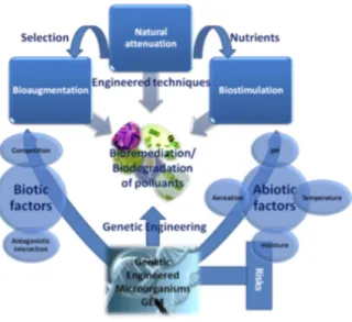
Figure 1.2 Bioremediation of pollutants utilizing biodegradation abilities of microorganisms in-clude the natural attenuation, although it may be enhanced by engineered techniques, either by addi-tion of selected microorganisms (bioaugmentaaddi-tion) or by biostimulaaddi-tion, where nutrients are
add-ed………..…8
Figure 1.2 Laccase catalytic cycle. [1]………11
Figure 1.3 - Schematic representation of the copper centers in a laccase……….13
Figure 1.4 Catalytic cycle of a laccase-mediator oxidation system and some example of laccase mediators…..8
Figure 1.5 Oxidation of ABTS in presence of laccase……….. …………19
Figure 1.6 Acid and base catalyzed hydrolysis reactions in the sol-gel process. Depending on the type and amount of water and catalyst present, hydrolysis may go to completion so that all the –OR groups are completely replaced by –OH, or stop while the alkoxide is only partially hydro-lyzed…...14
Figure 1.7 Electrospinning setup……….………..…23
Figure 1.8 cholineDHP structure………..…..27
Figure 2.1 SEM disc with coated samples………... 43
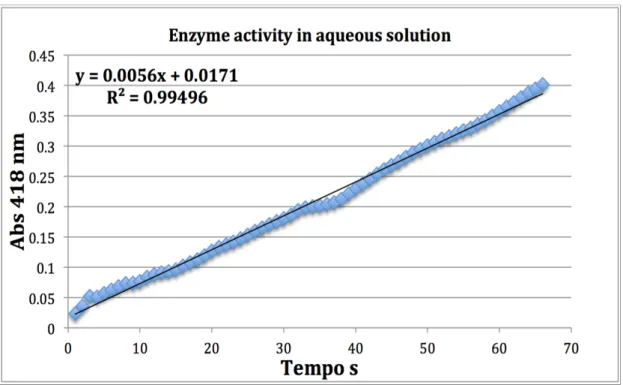
Figure 3.1 Absorbance as a function of time for the oxidation of ABTS in 100 mM phosphate buffer at pH 6……….. 46
Figure 3.2 Absorbance as a function of time for the oxidation of ABTS in acetoni-trile………..………....47
Figure 3.3 graphic representation of the absorbance over time of the enzymatic degradation of methyl red dye by the Trametes versicolor laccase at room temperature………...48
Figure 3.4 On the left side it is shown the solidification of the sol-gel solution on the tip of the needle, and on the right side the formation of an electrospray of gelatin…………..………..52
Figure 3.5 Multi layer membrane and a piece of membrane cut off for SEM analy-sis……….…54
Figure 3.6 Ion jelly-based films with entrapped laccase testing positive for enzyme activity us-ing the ABTS assay………56
Figure 3.7 a) PVA films with entrapped laccase testing positive for enzyme activity using the ABTS assay. b) PCL films with entrapped laccase that yielded negative ABTS as-says………...56
Figure 3.8 SEM images of TMOS fibers produced solution 1 (table 3.1): A) 1000 x amplification; B) 10000 x amplification. C) Fibers’ diameters distribution………57
Figure 3.9 SEM images of TEOS fibers produced solution 3 (table 3.2): A) 1000 x amplification; B) 10000 amplification. C) Fibers diameters distribution……….….. ..57
Figure 3.10 A) SEM image of TMOS fibers produced from a PVA 8% solution (table 3.3)……….…..…58
2
Figure 3.11 SEM image of TMOS fibers produced from a PVA 25% solution (table 3.3), B)
Fi-bers diameter distribution……….…..58
Figure 3.12 SEM image of TEOS fibers produced from a PVA 8% solution (table 3.3), B) Fibers diameter distribution... ………..……….59
Figure 3.13 SEM image of TEOS fibers produced from a PVA 25% solution (table 3.3), B) Fi-bers diameter distribution……….…………. 59
Figure 3.14 (a) SEM of PCL with 50 % of each solvents from solution 1 table 2.1, and (b) repre-sent the standard variation of the fibers diameters………. 60
Figure 3.15 (a) SEM of PCL with 75 % of DMC and 25% DMF of solvents, solution 1 table 2.1, and (b) represent the standard variation of the fibers diameters... 61
Figure 3.16 (a) SEM of PCL with 10% chloroform, solution 1 table 2.1, and (b) represent the standard variation of the fibers diameters... ………61
Figure 3.17 a) SEM of PVA fibers, and (b) represent the standard variation of the fibers diame-ters ………...………61
Figure 3.18 Multi layer membrane………..….…. 62
Figure 3.19 EDS analysis of the multi layer membrane………...……63
Figure 3.20 Absorbance as a function of protein concentration. ……. ………..64
Figure 3.21 Membranes tested for enzyme activity when immersed in aqueous and non-aqueous media containing ABTS………65
Figure 3.22 Enzyme leaching assay……… ……….……...65
Figure 3.23 Cross-linked enzyme activity in aqueous medium………...66
Figure 3.24 The first image shows the membrane emerged in water and second one its after 24 drying in incubator……….. ………....67
3
List of tables
Table 1.1 Properties of some bacterial, fungal, and plant laccases………. 12
Table 1.2 Immobilization methods………. 15/16 Table 2.1 Concentrations used to prepare sol-gel solution with PVA………33
Table 2.2 Concentration used to prepare sol-gel solution with PVA………..33
Table 2.3 Variation of HCL and PVA concentration for sol-gel solution...34
Table 2.4 Concentration used for ion jelly solution ……….…… 35
Table 2.5 Preparation of PCL solution with different solvents and concentrations………..…37
Table 2.6 Electrospinning setup for TMOS fibers with PVA. ………... 38
Table 2.7 Electrospinning setup for TEOS fibers with PVA………. 38
Table 2.8 Electrospinning setup for Ion jelly solutions………. 39
Table 2.9 Electrospinning setup for Ion jelly solutions with fish gelatin………39
Table 2.10 Co-axial electrospinning setup……….. 40
Table 2.11 PCL fibers for multilayer membranes electrospinning setup….. ……….40
Table 2.12 PVA fibers for multilayer membranes electrospinning setup……….…. 40
Table 3.1 Core solution composition, using porcine gelatin……….……51
5
7
1 Introduction
1.1 Bioremediation
The human commitment to create the leading-edge civilization that we live in has led to a sizable industrialization and a massive advance in technology. However this growing affects considerably worldwide environment, and one of the major preoccupations is water pollution. Water is a huge resource on earth but only 3% of it is without salt, two-thirds of which are in the form of glaciers and ice caps.[2]
In the previous decades, there have been numerous undertakings to create cost-effective and eco-friendly options to conventional waste treatment methods. Among all the alternatives bioremediation has emerged as the utmost desirable ap-proach to clean up the environment and to restore its original status.[3]
Microbial remediation is the application of microorganisms to eliminate haz-ardous wastes. This process can exist on its own in the environment, such as natural attenuation or intrinsic pathways of habitats. Bioremediation can be used at the sce-ne of infection (in situ) or on contamination removed from the original site (ex situ). If the contamination takes place in the soil or sediments, it can involve land tilling in order to expose the nutrients and make oxygen more highly available to the micro-organisms.[2]
Some examples of bioremediation strategies (Figure 1) are phytoremediation (plants), biosorption (dead microbial biomass), bioaugmentation (artificial introduc-tion of viable populaintroduc-tion), bioaccumulaintroduc-tion (live cells) and some others that have been used to render harmless various contaminants, with proportionately low cost, low technology techniques and high public acceptance.
Enzymatic remediation is an alternative to microbial remediation, which re-lies on the action of biocatalysts capable of degrading the target pollutants. Enzymes can be used intracellularly, or as isolated enzymes.[4]
1.2 Phenolic compounds
Among the water pollutants that cause concern are the phenolic compounds, which are released into the natural water resources from a variety of chemical indus-tries, such as coal and petroleum refining, phenol manufacturing, resin paint, plastic and varnish, textile units using organic dyes, pharmaceutical, among others. [5]
8
Phenol (C6H5OH), also known as benzenol or monohydroxybenzene, is the simplest member of the group of phenolic compounds. It is an organic compound characterized by a hydroxyl (-OH) group attached to a carbon atom that is part of an aromatic ring. The hydroxyl group makes it soluble in water, and the aromatic ring lends it high hydrophobicity that makes it soluble in organic compounds as well, which is the main factor for phenol penetration in organisms.[6]
Phenols and phenolic compounds have been demonstrated to be the greatly re-sistant and obstinate to natural degradation, and hence persistent in the environ-ment. This persistence enables long range transportation to different locations, bio-accumulation in human and animal tissue. The infection in humans affects several biochemical functions, creates central nervous system disorders and may lead to a coma collapse. It may also attack the muscular system, provoking pain, convulsions, weakness and tremors. Exposure to phenol may cause also skin burning and erosion. In humans eyes it can cause conjunctional swelling, corneal whitening and finally blindness. Studies have proven that chronic administration of phenols to animals leads to pathological changes in skin, oesophagus, lungs, liver, kidneys and also urogenital tract.[7] The demonstrated changes are mainly induced by lipid peroxida-tion that is responsible for damage and finally degradaperoxida-tion of cell membrane. Other studies point to mutagenic activity of phenol. This compound led to synthesis inhibi-tion and replicainhibi-tion of DNA in Hela cells and damage reparainhibi-tion of DNA on diploid
Figure 1.1 Bioremediation of pollutants utilizing biodegradation abilities of microorganisms include the natural attenuation, although it may be enhanced by engineered techniques, either by addition of se-lected microorganisms (bioaugmentation) or by biostimulation, where nutrients are added. [76]
9 human fibroblasts. E.g. hydroquinone (1.4-dihydroxyphenol) causes damages to chromosomes in human lymphocytes, increasing deletion ratio.[6]
Several phenolic compounds are included in the Environmental Protection Agency (EPA) Priority Pollution List. However there are phenolic compounds, such as oleuropein or hydroxytyrosol, which exist in virgin olive oil, that have a positive effect on certain physiological parameters, such as plasma lipoproteins, inflammato-ry markers, antimicrobial activity and bone health. Other species with positive ef-fects on human health are phenolic compounds from green tea, such as those from catechin derivatives, flavonols and phenolic acids, whose bioactivity is associated to reduction of severe illnesses such as cancer, cardiovascular and neurodegenerative diseases.[8]
Phenolic dyes are an important group of phenolic compounds. These dyes can be of natural origin or produced synthetically, and may be used to impart colour to various materials, such as textiles, paper, leather, hair, animal hair, photography, and also in food since due to their chemical structure, dyes are resistant to the dis-appearance of colour by exposure to light, water and other chemical compounds.[9]
1.3 Remediation of phenolic compounds
For phenol remediation there are several approaches, such as adsorption using activated carbon, wet oxidation, also called wet air oxidation, which uses de proper-ties of oxygen to remove organic and inorganic compounds at elevated temperature and pressure, photochemical oxidation, based on supplying energy to organic con-taminants by UV irradiation,[10] biological treatments that require the involvement of a specific microorganism to degrade the organic pollutant, enzymatic treatment, and also chemical oxidation that involves the use of chemical agents to eradicate or convert the contaminants to harmless or less toxic compounds.
Phenolic compounds are normally extremely strong reducing agents, and therefore their oxidation takes place in a short time.[11]
1.3.1 Biodegradation of phenolic compounds
Wastewater treatment via a biological pathway has been shown to be an eco-nomic alternative to other types of treatments, since the cost of biological material can be 5 to 20 times lower than that of chemical treatments. The microorganism sur-vives with carbon as a source of energy and inorganic salts or nutrients to reproduce and maintain its metabolic activities and cycles.
10 There are several parameters that affect the biodegradability of an organic pollutant, such as its chemical structure and concentration, pH, temperature, availa-bility of oxygen in case of aerobic processes.[12] The biodegradation procedure leads to conversion of these contaminants to harmless or simple inorganic compounds, such as water and CO2. One example of a large scale bioremediation process is the clean-up of spilled oil in the Alaskan shoreline of Prince Williams.[13]
The microorganisms most used in remediation are bacteria and fungi. Biodeg-radations based on free, suspended microbial cells or biofilms have proved to be very efficient because of higher cell concentration per unit volume of bioreactor and higher cell resistance to the toxic effect of phenolics. This method is very promising because it can use natural immobilized cells or biofilms. The latter are superior as a result of large biofilm support surface, hydrodynamic conditions, high mass transfer rates of both oxygen and substrate, and very good contact between the solid and liq-uid phase.[14]
A relevant fungal bioremediation pathway involves enzymatic systems with suitable mechanisms of action for the target compounds, which under optimal cul-ture conditions are produced fast and in adequate amounts. The demanding step in aromatic compounds metabolism is the destruction of the resonance structure by hydroxylation and division of the benzoid ring, which is carried out by a dioxygen-ase-catalysed reaction in the aerobic system. A good example of enzymes suitable for this degradation includes oxygenases hydroxylases, peroxidases, laccases, tyrosi-nases and oxidases, all belonging to the class of oxido-reductases.
Enzyme bioremediation has become an attractive approach for removing chemicals that are harmful to the environment [15]. The performance of enzymes in the degradation of dyes has been widely studied, owning to the fact that enzymes can efficiently cleave the dye structure. [16].
1.3 Laccases
Laccases have been studied since the nineteenth century. In 1883 a laccase was isolated from the Japanese lacquer tree Rhus vernicifera. In 1896, Bertrand and La-borde showed the presence of a laccase in a fungus.
Most of the laccases used today are isolated from ascomycetes, deuteromycetes and basidiomycetes fungi, namely from white rot mushroom from wood, such as laccases from Trametes versicolor, used in this work, from Trametes hirsuta, or Trametes
11
1.3.1 Structural and molecular properties
Laccase is a blue copper protein, also known as a polyphenol oxidase, which catalyzes the oxidation of a wide variety of organic and inorganic substrates, includ-ing mono-, di-, and polyphenols, amino phenols, methoxy phenols, aromatic amines and ascorbate, via the concerted transfer of four electrons from the target species to molecular oxygen, which is thereby reduced to water.
A common laccase reaction is shown in Figure 1.2, where diphenol goes through a 4-electron transfer oxidation reaction that yields an oxygen-centered free radical, which subsequently can be oxidized to a quinone via another 4-electron transfer to molecular oxygen. The radical can also go through a non-enzymatic cou-pling reaction (polymerization) with the quinone.[17]
Structurally, a laccase molecule contains four copper atoms per monomer ex-plicar, allocated in three different sites, which play a crucial role in the catalytic mechanism. The four copper atoms can be divided in three different binding sites, indicated as T1, T2 and T3, with different functions (Figure 1.3). T1 is reduced by the ox-idized substrate, and then transfers electrons to the tri-nuclear copper center T2/T3, where a third electron transfer step takes place, to molecular oxygen. [18], [19]
The structural orientation of the T1 copper is organized via two nitrogen atoms from two histidines (His) and a sulphur atom from a cysteine residue (Cys), which is responsible for the blue color of the enzyme. There is a fourth residue involved, of-ten a phneyalanine (Phe). The T2 copper chain involves two histidines, and T3
12 volves six histidines. In the T2/T3 coper center there occurs the reduction of oxygen and water release. [20]
Figure 1.3 - Schematic representation of the copper centers in a laccase.[20]
Fungal laccases have an isoelectric point ranging from 3 to 7, while plant lac-cases, have an isoelectric point of around 9. This leads to lower pH ranges for opti-mum catalytic function by fungal laccases than for plant laccases. Fungal laccases function well under acidic conditions, with an optimum pH of around 3.6 to 5.2. Ta-ble 1 shows the properties of laccases from different sources.[21]
1.3.2 Mediators
The oxidation rate of a substrate by laccase depends on the difference in redox potential between the substrate and the enzyme, and is favored when the laccase has a higher redox potential and the substrate has a lower redox potential.
When the substrate has a higher redox potential, or when it is of larger size, it may still be oxidized by laccase with the help of a mediator. A mediator is a low mo-lecular weight compound whose purpose is to carry electrons to and from the en-zyme, thereby facilitating the oxidation of the substrate (Figure 5). A good mediator must be a good substrate for the enzyme and its reduced and oxidized forms must be stable but must not interfere with the overall enzymatic reaction.[20]
ABTS (2,2'-azino-bis(3-ethylbenzothiazoline-6-sulphonic acid) was the first ef-ficient mediator reported for laccases, and it is most commonly used for these en-zymes. This and other laccase mediators are included in Figure 1.4
13 ABTS acts as a co-oxidant that cooperates with the enzyme electron transfer system, and is chemically oxidized via two steps involving the radicals ABTS+ and ABTS2+ (Figure 1.5). This mechanism is responsible for the greblue color indicative of en-zyme activity. [22]
1.4 Enzyme immobilization
The main deficiencies of many important enzymes for their use in industrial applications are their low stability and productivity, and high production costs.
The most frequently used stabilization method is immobilization, which allows for enzyme reutilization, facilitation of separation, and of reaction control. Enzyme immobilization can affect optimum pH and temperature for enzyme function,
kinet-Figure 1.4 Catalytic cycle of a laccase-mediator oxidation
system and some example of laccase mediators. [20]
14 ics parameters, and may strengthen protein structure. Higher thermostability of the enzyme allows conducting processes at higher temperatures and so it reduces reac-tion time. The advantages and disadvantages of enzyme immobilizareac-tion are shown in below.[23]
Enzyme immobilization was performed for the first time by Nelson and Grif-fin in 1916. They adsorbed the enzyme invertase on activated carbon and alumina, with the retention of its catalytic activity.[24] However, the development of enzyme immobilization processes started almost fifty years later. In 1969, in Japan, the first industrial process using immobilized enzymes for the production of L-aminoacids was implemented, and soon after, in 1972, in the US, a process was launched using immobilized glucose isomerase for the isomerization of glucose to fructose and production of the so-called high fructose corn syrup. From then on, many new im-mobilization methods have been reported in the literature.
Different methods based on physical and chemical mechanisms are used for enzyme immobilization on solid materials and gels.[25] The chemical methods in-clude covalent bonds between the enzyme and the support, cross-linking between the enzyme and the support, and enzymatic cross-linking by multifunctional agents.
Advantages
Easier separation and recovery of the enzyme and products Reusability"
Increase of thermal stability and resistance against denaturing agents Reaction can be stopped more easily"
Continuous operations can be easier to achieve" Higher flexibility in the design of bioreactors"
Prevents the contamination caused by the protein in the final product Microbial contamination is easier to control
Disadvantages
Lower enzymatic activity caused by the immobilization process Increase of the Michaelis-Menten constant
15 The physical methods involve adsorption, entrapment of enzymes in insoluble pol-ymeric gels (polpol-ymeric entrapment) or in micelles (encapsulation).[26]
Table 1.2 shows a scheme of the classification methods used for enzyme immo-bilization, with their particular advantages and disadvantages.[27] ,[28],[29].
Table 1.2 Immobilization methods
Immobilization Method
Advantages Disadvantages
Chemical
Covalent bond Dissipated organization of enzymes Full interaction between the enzyme and any external interface
Possible inactivation of the enzyme by any ex-ternal agent
Single covalent bond with cross-linker
Same mass used for enzyme and support. Facilitated linkage, because of geomet-rical shape.
Enzyme is attached, but there is no evidence of substantial increase of the enzyme stability Enzyme can present deactivation by conforma-tional changes induced by distorting agents
Multipoint covalent bond with cross-linker
Increase of the enzyme stability by reduc-ing the conformational changes of the enzyme induced by any distorting agent (heat, organic solvents, extreme, pH val-ues)
High need of geometric congruence between the enzyme and the support
The mass of the support is considerably higher than the mass of the immobilized enzyme
Enzyme crosslink-ing
The mass of the enzyme aggregate can be comparable to the mass of the enzyme Simplicity in operation
Interaction between any external interface and the enzyme is conditioned by its position in the aggregate
Poor reproducibility and mechanical stability Handling problems
16
1.4.1 Immobilization of laccase
Various approaches for laccase immobilization have been studied, such as ad-sorption, covalent binding, crosslinking and entrapment.
E.g. laccase from Pleurotus sajor-caju was immobilized by adsorption by Rubenwolf et al,[30] for application in a biofuel cell cathode. Rahman et al [31], im-mobilized a laccase on gold nanoparticles through covalent binding to build a cate-chin sensor[31]. Laccase from the white rot fungus Coriolopsis polyzona was im-mobilized for the first time through the formation of cross-linked enzyme aggregates to eliminate endocrine disrupting chemicals, by Cabana et al,[32]. Laccase for decol-orisation of a dye was entrapped in lens-shaped, micron-sized semipermeable hy-drogel capsules of polyvinyl alcohol [33]
Adsorption
No need to functionalize the support (or a more simple method is needed) Immobilization takes place by electrostat-ic or hydrophobelectrostat-ic binding, without the need of adding more compounds
If the substrate is very large or hydrophilic, the near presence of the hydrophobic support sur-face may generate some steric hindrances, re-ducing the activity of the enzyme
Attachment is weaker than by covalent binding
Entrapment
Encapsulation
Retains the enzyme in its natural form in capsules of different size
Reduces the contact of the enzyme with the external interface (depends on the diffusion of different compounds through the capsule)
Enzymatic retention hardly depends on the po-rosity of the capsule
Enzyme can present deactivation by conforma-tional changes induced by distorting agents
Polymeric entrap-ment
Retains the enzyme in its natural form, useful for flat surfaces
Reduces the contact of the enzyme with the external interface (depends on the diffusion of different compounds through the layers)
Enzyme can present deactivation by conforma-tional changes induced by distorting agents Possible appearance of nanoenvironments that can alter the operation of the enzyme
17
1.4.2 Biocatalytic fibers
Fibers obtained by electrospinning provide a very large area of contact, and this has led to the use of electrospun fibers, or electrospun fiber membranes, to im-mobilize enzymes. For example Ling Ge et al [34] imim-mobilized glucose oxidase with-in electrospun nanofibrous membranes for food preservation. A novel food packag-ing material was obtained by immobilizpackag-ing glucose oxidase in PVA/CS/tea extract electrospun nanofibrous membrane.[34]
Immobilization via encapsulation often involves diffusion limitations for the chemicals or metabolites that must be exchanged between the enzyme and its sur-roundings. Immobilization within thin-walled fibers, on the other hand, facilitates the diffusion of chemicals species into and out of the enzyme microenvironment. This and the already referred large surface area are advantages of this immobiliza-tion approach, which has been explored in the encapsulaimmobiliza-tion of bacteria [35]. These authors used co-axial fibers, with an outer, protective shell made of silica, and a core made of a polymer suitable for the biological material. For example a laccase immo-bilization approach in fibers used by Dai Yunrong et al [36], with four types of lac-case-carrying electrospun fibrous membranes (LCEFMs), with high laccase-catalytic activity and sorption capacity, were fabricated by emulsion electrospinning. These LCEFMs were composed of beads-in-string structural fibers, with nanoscale pores distributed on the surface and active laccase encapsulated inside. This obtained structure could protect laccase from external disturbance, resulting in that all of the four LCEFMs retained more than 70% of activity relative to free laccase, and after glutaraldehyde treatment, their storage and operational stabilities were definitely improved. [37]
When compared to the use of free enzymes, membrane bioreactors such as those indicated above allow additionally for better product recovery, reuse of en-zyme, and continuous operation of the reactor [27]. The operating conditions, such as substrate concentration, immobilization matrix, types of immobilization, and characteristics of the membrane considerably influence the performance of mem-brane bioreactors [38].
1.5 The sol-gel process
The sol-gel process can be described as a chemical route to synthesize glassy or ceramic materials at relatively low temperatures, based on wet chemistry processing, which involves preparation of a sol, its gelation, and then removal of the liquid with-in the porous gel.[39]
18 Use of inorganic ceramic and glass materials in the sol-gel process began as ear-ly as the mid-1800s by Ebelmanl and Graham who studied silica gels. Hydroear-lysis of tetraethyl orthosilicate (TEOS; Si(OC2H5)4) under acidic conditions yielded SiO2 in the form of a “glass-like material”.
In the 1950 and 1960s, Roy and co-workers used the sol-gel method to synthe-size a large number of novel ceramic oxide matrices, involving AI, Si, Ti, Zr, etc.[40] During the last few decades, the sol-gel method has been widely used as an al-ternative technology to prepare a variety of substances in such forms as monoliths, powders, tubes and fibers. [41]
Sol gel processing involves generation of colloidal suspensions (sols), which are subsequently converted to viscous gels, and then to solid materials. A sol is defined as a stable dispersion of solid colloidal particles in a liquid phase. Colloids are classi-fied as solid particles with diameters of 1-100 nm which are not affected by the grav-itational force, while a gel is considered as an interconnected network with pore size in sub-micrometer dimensions, and polymeric chains whose average length is great-er than 1 µm.[42]
1.5.1. Sol-gel reaction mechanism
Since this thesis involves the synthesis of silica based fibers using the sol-gel method, the sol-gel process will be explained in terms of silica.
It is difficult to divide a sol-gel process into different stages, as different processes mostly occurring simultaneously. However, the occurrence of the following major stages is acknowledged: • Hydrolysis • Condensation • Poly-condensation • Aging • Drying 1.5.2.1 Hydrolysis
It consists in a reaction between water and the silica precursor, when hydroxyl ions get attached to the silicon part of the precursor. The major silica precursors used are tetramethyl and tetraethyl orthosilicate (TMOS), (TEOS). The first path of hydrolysis of these precursors is slow and to accelerate it an acid or a basic catalyst is used (Fig-ure 1.6). Mineral acids, ammonia, acetic acid, HF, KF, amines, KOH, titanium alkox-ides and vanadium alkoxalkox-ides are known catalysts of the sol- gel process. [43]
19 Different extents of hydrolysis reaction in the acid and base catalyzed processes can be justified on the basis of electronic effects. The ethoxy groups have less of an elec-tron donor character than the alkoxy groups, and therefore the reaction rate decreas-es in acid catalyzed reactions as the positively charged transition state becomdecreas-es ldecreas-ess stabilized when more alkoxy(-OR) groups are replaced by hydroxyl (-OH) groups. [44]
1.5.2.2 Condensation
Generation of siloxane bonds requires a polymerization that can be alcohol condensation (equation 2.1) or water condensation (equation 2.2)
Figure 1.6 Acid and base catalyzed hydrolysis reactions in the sol-gel process. Depending on the type and amount of water and catalyst present, hydrolysis may go to completion so that all the –OR groups are completely replaced by –OH, or stop while the alkoxide is only partially hydrolyzed.[39] [41]
Eq.2.1 Eq.2.2.
20 Condensation takes place to maximize the number of siloxane linkages and minimize the number of terminal hydroxyl (silanol) groups through internal con-densation. Although the sequence of condensation requires both depolymerization and presence of monomer (whether already present in the system or generated as a result of depolymerization), the rate of depolymerization is found to be reduced in alcohol-water systems than in aqueous media. The initial condensation reaction is followed by polycondensation that involves formation of more siloxane linkages and a stronger network.[41]
1.5.2.3 Gelation
It is generally observed that the gelation process begins with the formation of fractal (a seemingly irregular structure formed by repeated subdivisions of a basic form and having a pattern of regularity) aggregates that grow until they impinge on each other. These clusters link together through chemical, hydrogen or van der Waals’ bonds forming a network which ultimately results in the generation of a gi-ant three dimensional spanning cluster that extends throughout the sol and coexists with the sol phase that contains many small clusters.[39]
At this point, the mixture has a high viscosity but low elasticity and it still holds many sol particles entrapped and entangled in the spanning cluster. The gelation point of any system is easy to observe qualitatively but quite difficult to measure an-alytically. Generally, gel point or gelation time is defined as the point at which a sol can support stress elastically. Although the reactions that bring about gelation in sil-ica continue long after the gel point because of the large concentration of labile hy-droxyl groups on the surface of the silica network [45], it is established that the sharp increase in viscosity that accompanies gelation essentially freezes in a particular pol-ymer structure at the gel point. This ”frozen in” structure may change a lot with the passage of time depending on the pH, temperature, solvent and the drying condi-tions. [46]
1.5.2.4 Aging
While a gel maintains solvent in its pores, its structure and properties contin-ue to change long after the gel point. This process is called aging. Aging of a gel, also called syneresis, involves maintaining the cast object for a period of time (hour, days or months) completely immersed in either the mother liquor or some other specific solvent used to control the properties of the final product. During aging,
polycon-21 densation continues, which increases the thickness of inter particle necks and de-creases the porosity. The strength of the gel thereby inde-creases with aging. An aged gel is considered quite capable to resist cracking during drying [44].
1.5.2.5 Polymerization
Increase in the connectivity of the network produced by condensation is iden-tified as polycondensation or polymerization. In alkoxide based systems, usually the hydrolysis reaction goes to completion in a short span of time, especially when cata-lyzed by acidic species. Through Nuclear Magnetic Resonance (NMR) and Raman studies of the silica gels synthesized in alcoholic solutions, it is discovered that the number of bridging bonds keeps on increasing long after gelation [47]. Since the chemical reaction is faster at high temperatures, aging can be accelerated through hydrothermal treatment that increases the rate of condensation reaction. In addition to condensation (eq. 2.3), aging can also result in further hydrolysis (eq. 2.4) or re-esterification, which is the reverse reaction (eq. 2.5) and can be suppressed by using excess water. [41]
1.5.2.6 Drying
Drying of a gel is a crucial step that is mainly governed by the capillary pres-sure of the solvent, interfacial tension of the solvent, the pore radius and the thick-ness of a surface adsorbed layer. All these parameters are quite critical as it is the gradient in the capillary pressure during evaporation that causes collapse in the sur-face structure. The smaller pores are capable to induce greater damage to the gel be-cause of their enormous capillary pressure [48]. The capillary pressure can only be reduced by using solvents with low surface tension or by preparing a gel with larger pore equation 3.5. However, there are chances for a reversible shrinkage, which might occur during drying. The gel springs back during the last part of drying. This reversible shrinkage occurs if gels have stiffness high enough so they are not forced beyond yield by capillary pressure during drying or if the inner surface of the wet gel has been modified i.e., by silylation, to hinder siloxane bond formation during drying. [41]
Eq.2.3 Eq.2.4 Eq.3.5
22
1.6 Electrospinning
1.6.1 Nanofibers
In the last years there has been a high increase in the use of nanostructured ma-terials in several fields, motivated by the good performance of these mama-terials as well as ease of manufacturing with good control of material properties.
The large surface to mass ratio is one of the important properties of nano-fibers. Until now nanofibers have been produced commercially with silica, or alumi-na, and silica has demonstrated good performance as regards chemical stability and thermal capacity.[49]
1.6.2 Electrospinning process
Electrospinning was first studied by Formhals in the 1930s, and gained a con-siderable attention in the 1990s.
Electrospinning is a synthesis method that, like drawing, phase separation, template synthesizes, and self assembly, can be used to fabricate, easily and efficient-ly, fibers with size ranges around 10 to 100 nm.
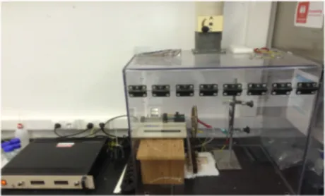
A typical setup for the electrospinning process consists of three major components: 1. A high-voltage supplier: A direct current voltage in the range of 5–35 kV is
necessary to generate electrospun fibers. Alternative current potentials are al-so used, but in a less widespread way. "
2. A capillary tube with a spinneret (needle or pipette of small diameter): The spinneret is connected to a syringe in which the polymer solution or melt is hosted. The syringe is usually associated to a pump to control the rate of fluid flow. As shown in Figure 1.7 the capillary tube and the needle may be ar-ranged vertically, but more often they are arar-ranged horizontally to minimize the effect of gravity on drop formation.
3. "A metallic collector: Commonly the collector is a conductor metallic screen. With this type of collecting device, the fibers are generally deposited as a ran-dom network. However, for many applications it is desirable to have aligned fibers or a specific arrangement of accumulated fibers. By using patterned electrodes, conductive substrates separated by a nonconductive gap, disc col-lectors, or other methods, varying degrees of fiber alignment can be achieved.
23 Many nanofibers assemblies and their associated methods are presented in reference.[49] " 1.6.3 Electrospinning parameters
To synthesize a fiber with certain specifications it is necessary to control some parameters, such as solution composition and concentration, viscosity, applied field, flow rate, collector distance, and ambient condition.
The solution composition has an important effect on electrospinning, related to its concentration. If the solution has a lower concentration, an electrospray process can occur, because there are no conditions for fiber elongation.[50] Likewise, if the concentration is higher than required, it is not possible to form Nano scale fibers. The viscosity of the solution is related to its concentration. If the solution has a high viscosity, no fibers can be produced because the solution cannot be pumped through the needle, whereas a low viscosity leads to electrospray.[51]
The distance between the end of the needle and the collector affects the solvent evaporation rate, enabling fiber production. If this distance it too short, there is no time for solidification, whereas a higher distance may provide disruption of the pol-ymer elongation and lead to formation of beads.
The flow rate is another important parameter, which affects the morphology of the fibers. With a very slow flow rate, the fibers obtained are thin, because of com-plete evaporation of the solvent before reaching the collector. A high flow rate with-drawal from the nozzle produces a thick fiber with beaded structure, due to the ina-bility of the jet to dry before reaching the collector. [52]
24 A crucial aspect to consider in the electrospinning process is the applied volt-age. The applied voltage turns the droplet that comes from the nozzle into a jet, which lands as a fiber on the collector. If the applied voltage increases, so does the electrostatic repulsive force on the fluid jet that mostly results in contraction of the fiber diameter. One might assume that the voltage of the electrospinning setup con-trols the fiber diameter, but the latter varies also with the nature and concentration of the polymer, and the tip to collector distance. [53]
The environmental conditions also affect the solution properties, as well as the solvent evaporation rate, which in turns results in changes in fiber morphology. A higher temperature, on the other hand, results in faster evaporation of the solvent, making the fibers thinner. The humidity values also influence fiber morphology, since a more humid atmosphere results in slow solvent evaporation that leads to the formation of thicker fibers, while a less humid atmosphere accelerate the evapora-tion rate, which may become so fast that the solute clogs the needle of the spinneret.[49]
1.6.4 Co-axial Electrospinning
A coaxial fiber is essentially built from two different materials: one on the out-side of the fibers, denominated the “shell”, and the other on the inout-side of the fibers, called the “core”. Coaxial fibers can have different mechanical, physical and degra-dation properties in the core and in the shell, depending on their respective composi-tions.[54]
The only difference between the normal electrospinning setup and the coaxial electrospinning setup is the needle apparatus. In terms of the material selection, the solvents used in each solution must be immiscible, and the shell solution must be highly electrospinnable. The voltage and the distance between the collector must al-so be optimized for the coaxial electrospinning process. The increase of voltage in coaxial electrospinning could provide a separation of the core and shell, despite a low voltage also could produce a good fiber production. [55]
1.7 Ionic liquids and ion jelly
1.7.1 Ionic Liquids
One of the approaches in this work is to use an ionic liquid in the manufacture of co-axial fibers.
Studies on ionic liquids started in the nineteen-century with the formation of an ionic liquid in the course of a Friedel-Crafts reaction that produced a “red oil”,
25 later discovered to be composed of a carbocation and a tetrachloroaluminate anion. In 1914 an ionic liquid was synthesized for the first time (ethylammonium nitrate), by Paul Walden. Interest in ionic liquids grew, as it became clear that they could be useful for many applications, such as electrolytes for batteries and metal electroplat-ing systems. [56]
Ionic Liquids are substances fully made of ions, with a melting point below 100 ºC. Ionic liquids are a complex network of ions mediated by non-specific interactions (electrostatic charges) and specific interactions (hydrogen bonding). The asymmetric form of the ions and their bulky/non-linear association creates a reduction in bond strength between the ions and a corresponding reduction in the columbic interac-tions, which results in a lowering of the salt melting point [57]. A subclass of these materials known as ‘room temperature ionic liquids’ (RTILs) have moved to the fore-front of ionic liquid research due to their melting temperatures being below 30°C. These liquids exhibit the most favorable properties for solvent use due to their for-mation of stable, non-volatile liquids in ambient room conditions while also main-taining their stability over large temperature ranges. Ionic liquids differ from other
classes of solvents due to the binary, charged nature of the liquids when compared to atomic or molecular solvents.[58]
Ionic liquids can be recycled, reducing chemical waste and increasing the life-time of the liquids, further adding to the ‘green’ aspects of ionic liquids [59]. For ex-ample, the hydrophobic nature of certain ionic liquids allows for the addition of hy-drophobic compounds that, once reacted, form hydrophilic products. The addition of water then allows for the removal of pure products and the removal of the ionic liquid for use once again a reaction medium. [60]
The vast numbers of available ions results in a theorized number of possible ionic liquids to be over 1014 combinations[61].For this reason, ionic liquids have be-come known as “designer” [56], whose customizability allows for the ability to en-dow specific properties upon the final liquid product.
In this work, it was used choline di-hydrogen phosphate (choline DHP) as the ion jelly ionic liquid, which is shown to give stability to biological substances, name-ly proteins such as ribonuclease and cytochrome c. The structure of choline DHP is shown in Figure 1.10.
26
Figure 1.8 cholineDHP structure
(http://www.churchoffreethought.org/freethought_101.php)
Ionic liquids can lend conductivity to polymeric materials, such as those used for enzyme-entrapment. This can be particularly useful when the enzyme catalytic mechanism involves charge transfer, as in the case of reactions catalysed by laccases. There are some reports on ionic liquids decreasing enzyme activity, but this may be circumvented by the increase in enzyme stability that they impart. [62].
1.8 Ion Jelly
The ion jelly interpretation starts with a combination of ionic liquid (IL) with a gel polymer, and can be divided into three major types: gelation of ILs within poly-mers/ biopolymers, in situ polymerization of vinyl monomers in ILs, and polymeri-zation of ILs containing polymerizable groups. These approaches are very interest-ing ways to achieve higher ionic conductivity without liquid components. [63], [64] [65], [66].
The procedure used in this work is based on gelation, which is a simple meth-od that permits a gometh-od compromise between the retention of the IL and its mobility inside the polymeric network. This approach combines the mechanical properties of polymers with physico-chemical properties that are relevant for current solid-state polyelectrolytes in energy devices, such as dye-sensitized solar cells, supercapaci-tors, lithium ion batteries, and fuel cells [67].
1.9 Multi layered fiber membrane reactor
The initial objective of the work plan behind this thesis was to follow an ap-proach similar to that of Tong et al. (2014) and fabricate, using coaxial electrospin-ning, reactive fibers containing a laccase for phenol bioremediation, comprising an ion jelly core entrapping the enzyme, and a silica-based, mechanically resistant, po-rous shell.
The choice of silica was motivated by its thermal stability, relative inertness, low cost and biocompatible sol-gel transition at room temperature. Silica was com-bined with polyvinyl alcohol (PVA), which optimizes the sol-gel solution in different aspects. PVA acts as a thickening agent, providing viscosity adjustment to the
elec-27 trospinning solution, protects the biological material from the gelling silica precur-sors, adds flexibility to the membrane, and increases its porosity.
The choice of the ion jelly for the core was motivated by the good performance of oxido-reductases immobilized within this material.
Several difficulties that arose during the implementation of the workplan de-scribed above led to a different concept of fiber membrane, based on the production of a membrane layer by layer. The outermost top and bottom layers were made of silica-PVA fibers, and the inner layer, containing the enzyme, was no longer made of ion jelly, but was fabricated with wither polycaprolactone (PCL), or PVA.
29
30
32
2 Materials and methods
2.1 Enzymatic studies
The enzymatic studies were performed with methyl red indicator with pH limit (4,4-6,2) (Merck), choline dihydrogen phosphate, 98% (ABCR), acetonitrile (Carlo Erba), methylimidazolium dicyanamide, 98% (io-li-tec), 1-butyl-3-methylimidazolium tetrafluoroborate, 99% (io-li-tec), 1-ethyl-3-1-butyl-3-methylimidazolium ethyl sulphate, 99% (io-li-tec), sodium phosphate buffer prepared in lab with concen-tration of 100 mM, pH 5 and 6.
Enzyme: laccase from Trametes versicolor that did not require any step of purifi-cation and was obtained from sigma Aldrich (DE), (0.5 U/mg).
Enzyme mediator: 2,2-azinobis(3-ethylbenzothiazoline-6-sulfonic acid) (ABTS) diammonium salt ( ≥98% HPLC ) was supplied by Sigma-Aldrich (DE).
2.1.2 enzyme activity in aqueous solution
UV/Visible spectroscopy was used (Beckman coulter, DU 800).
To one cuvette 930 $L of 0.5 mM ABTS in 100 mM phosphate buffer at pH 6 was pipetted, and 50 $L of mM phosphate buffer at pH 6 was added to set the ab-sorbance = 0 line ((λ = 418 nm). Previously homogenized 20 $L of a 2.58 mg/mL lac-case solution was added and the absorbance was measured every 5 s for 210 s, keep-ing the solution homogenized ( ε = 36000 mM-1 cm-1).
2.1.3 enzyme activity in non-aqueous solution
0.5 mM ABTS in 100 mM phosphate buffer at pH 6 was used to set the absorb-ance = 0 line ((λ = 418 nm). Then 3 mg of laccase was added and thoroughly mixed. Stopping agitation made the enzyme precipitate very quickly. Then 1 mL of the solu-tion was withdrawn into a cuvette and absorbance was measured. This step was re-peated every 1 min for 8 minutes, and in between samples mixing continued.
2.1.4 effect of ACN in ABTS+ radical stability
After completing an aqueous solution laccase activity assay as indicated earlier, the cuvette was set aside and periodically absorbance was measured. To obtain an
33 accurate measurement, the solution in the cuvette was diluted. After color stabiliza-tion occurred, 200 $L of the solustabiliza-tion was mixed with 1.5 mL of ACN. Periodically, during 1 h, absorbance was measured to see if the blue colour imparted by ABTS+ disappeared through addition of a nonaqueous solvent.
2.1.5 enzymatic degradation of a dye
A 24 mg/L of methyl red solution was prepared in 10 mM phosphate buffer at pH 6, and was diluted so that its absorbance was close to 1,2.
To one cuvette 920 $L of diluted methyl red solution was pipetted, to set the absorbance = 0 line ((λ = 430 nm). Previously homogenized 80 $L of a 24.6 mg/mL laccase solution was added and the absorbance was measured every min for 15 min, keeping the solution homogenized (ε = 23360 mM-1 cm-1).
2.2 PVA Silica solutions for electrospinning
2.2.1 Chemicals
TMOS (tetramethyl orthosilicate; Si(OCH3)4; wt = 152.25 g/mol; density = 1.032 g/cm3; ≥ 98%), TEOS (tetraethyl orthosilicate; Si(OC2H5)4; wt = 208.33 g/mol; density = 0.933 g/cm3; ≥ 99%), methanol (wt = 32.04 g/mol; density = 0.792g/cm3; 99.8%), ethanol (wt = 46.07 g/mol; density = 0.789 g/cm3), polyvinyl alcohol (PVA; 87-90% hydrolyzed, wt = 30000-70000 g/mol, taken to be 50000 g/mol in all calcula-tions) , Enzyme: laccase from trametes versicolor from sigma Aldrich (DE), (0.5 U/mg), hydrochloric acid (HCl; wt = 36.46 g/mol; density = 1.19 g/cm3; ≥ 38%)
2.2.2 2.2.2 TMOS-based sol-gel
The procedure by Tong et al [35], was adapted for this work. The relative amounts of the various components of the sol-gel solution were varied and these changes were assessed by the ability to produce fibers by electrospinning.
PVA concentration was set as 18 wt% PVA was dissolved in deionized water at 60 ºC while stirring in a water bath for 50 min. A typical sol-gel solution with 1000 $L TMOS and different concentrations of methanol and water was prepared and thoroughly mixed. Then a HCl solution was added dropwise to a concentration of 4M. The solution was stirred at 60 ºC in a water bath for one hour. Afterwards 0,65 g of PVA per each ml of TMOS solution was slowly added to the TMOS solution and was thoroughly mixed for one hour by stirring in a water bath at 60 ºC.
34
Table 2.1 Concentrations used to prepare sol-gel solution with PVA.
Solu-tions TMOS ($L) Methanol ($L) H2O ($L) HCL ($L) PVA (18%) 1. 1000 300 215 13,3 0,65 g per 1 ml of TMOS 2. 1000 215 300 13,3 0,65 g per 1 ml of TMOS 3. 1000 257 257 13,3 0,65 g per 1 ml of TMOS 2.2.3 2.2.3 TEOS-based sol-gel
For the preparation of TEOS-based sol-gel solutions, the procedure adopted was also based on the work of Pizarda et al [68]. The procedure was the same as in section 2.2.2 with the required alteration of solutions regarding that for TEOS it is hydro-lysed by ethanol.
Table 2.2 Concentration used to prepare sol-gel solution with PVA.
2.2.4 Parameters variation
In this section the concentrations and percentage of HCl and PVA used were varied, while following exactly the same procedures as described in sections 2.2.2 and 2.2.3. Table 5 shows the changes in parameters.
Table 2.3 Variation of HCL and PVA concentration for sol-gel solution.
HCL (M) 0,001 0,01 0,1 1 2 4 PVA wt (%) 8 10 14 16 18 25 Solu-tions TEOS ($L) Ethanol ($L) H2O ($L) HCL ($L) PVA (18%) 1. 1000 203 203 13,3 18 (0,65 g per 1 ml of TEOS) 2. 1000 175 240 13,3 18 (0,65 g per 1 ml of TEOS) 3. 1000 240 175 13,3 18 (0,65 g per 1 ml of TEOS)
![Figure 1.3 - Schematic representation of the copper centers in a laccase.[20]](https://thumb-eu.123doks.com/thumbv2/123dok_br/19185461.947341/29.892.199.633.162.401/figure-schematic-representation-copper-centers-laccase.webp)

![Table 1.2 shows a scheme of the classification methods used for enzyme immo- immo-bilization, with their particular advantages and disadvantages.[27] ,[28],[29]](https://thumb-eu.123doks.com/thumbv2/123dok_br/19185461.947341/32.892.76.789.273.1071/table-scheme-classification-methods-bilization-particular-advantages-disadvantages.webp)