Development and optimisation of phase change material-impregnated
lightweight aggregates for geopolymer composites made from
aluminosilicate rich mud and milled glass powder
Gediminas Kastiukas
a, Xiangming Zhou
a,⇑, João Castro-Gomes
baDepartment of Mechanical, Aerospace and Civil Engineering, Brunel University London, Uxbridge, Middlesex UB8 3PH, United Kingdom bCentre of Materials and Building Technologies, University of Beira Interior, 6200 Covilhã, Portugal
h i g h l i g h t s
!PCM vacuum impregnation is very successful for expanded clay lightweight aggregate. !Polyester resin coating is able to retain all of the impregnated PCM from leakage. !Resin coating is chemically stable and neutral, also improving thermal conductivity. !Novel combination of geopolymer and thermal energy storing aggregates evaluated. !ME-LWA has a high energy storage capacity of 157 J/g.
a r t i c l e i n f o
Article history:
Received 30 September 2015
Received in revised form 24 December 2015 Accepted 10 February 2016 Keywords: Geopolymer Alkali-activated Mining waste Lightweight aggregate Expanded clay aggregate Thermal conductivity Phase change material Paraffin
Impregnation SEM
a b s t r a c t
Macro-encapsulated aggregates (ME-LWAs) consisting of expanded clay lightweight aggregates (LWAs) impregnated with a paraffin wax phase change material (PCM) was produced. To fully exploit the thermal energy retaining properties of PCM, it is fundamental to retain as much of the PCM as possible within the pores of the LWA. This paper investigates 3 different commercial materials to create a total of 14 different coating regimes to determine the most efficient coating method and material regarding its ability at retaining the PCM. The ME-LWAs are then further used as aggregates in geopolymer binders made from a combination of aluminosilicate rich mud and waste glass. Physical properties such as thermal conduc-tivity and mechanical strength are determined for the geopolymer binder with and without the addition of the ME-LWA. A polyester resin was determined to be the most suitable choice of coating material for the ME-LWA, producing a practically leak-proof coating. The ME-LWA was also determined to be chem-ically neutral, showed a 42% higher thermal conductivity than the LWA in their raw state and maintained a latent heat of 57.93 J/g before and after being used in the geopolymer binder. Carbon fibres and graphite spray were used to improve the thermal conductivity of the resin coating, however no significant increase was detected. Finally, the compressive strength and thermal conductivity results achieved are acceptable for applications in buildings for enhancement of their energy efficiency.
! 2016 Elsevier Ltd. All rights reserved.
1. Introduction
In our current time, large proportions of energy are still supplied from the exploitation of fossil fuels that are finite natural resources. Exploitation and usage of fossil fuels bring a negative impact on the environment. In response to this, different techniques have been studied related to space cooling and heating
in buildings to improve their energy efficiency using ‘active methods’[1–3]. It is also evident that more focus should be placed on the use of renewable energy sources that reduce environmental pollution and, at the same time, improve our quality of life [4]. According to the European Commission, buildings account for 40% of EU final energy demand, and the Horizon 2020 EU Framework Programme for Research and Innovation has made it a priority to deliver innovative, affordable and applicable technolo-gies for energy efficiency for building envelopes[5]. The initiative aims to reduce the total primary energy consumption of a building by at least a factor of 2, with great emphasis being placed on the
http://dx.doi.org/10.1016/j.conbuildmat.2016.02.029 0950-0618/! 2016 Elsevier Ltd. All rights reserved.
⇑ Corresponding author.
E-mail address:[email protected](X. Zhou).
Contents lists available atScienceDirect
Construction and Building Materials
development of prefabricated components with the re-use of recycled and residue materials from the construction and indus-trial sectors. By the end of 2020, all new buildings should meet the Energy Performance of Buildings Directive obligations and thus reach ‘nearly zero-energy’ performance levels using innovative, cost-efficient solutions while also integrating renewable energy sources. One of the most effective ‘active methods’ to reduce a building’s energy consumption is to incorporate a phase change material (PCM) as an additive into the desired building component. The building components used for the incorporation of PCM have ranged from actual cement powder[6], mortar [7] concrete [8], plastering mortar[9]and many others[10,11,12]. PCM’s have high latent heat storage densities and can, therefore, absorb thermal energy when transforming from solid to liquid or release it when turning back to solid[13]. This property allows the PCM to function as a heating and cooling system for a building since, during the daytime, the PCM in a building component absorbs surplus ther-mal energy by melting and at cooler temperatures during the night, will solidify and release thermal energy back into the envi-ronment. Incorporation of PCM’s into building components can be achieved primarily in three different ways: The first method is direct incorporation at the time of mixing. The second method is the immersion of the building component in liquid PCM. The third method is micro/macro encapsulation of the PCM[14]. The latter method is considered to be the most advanced and popular because it allows for better dispersion, eliminates direct interac-tion between PCM and host material and reduces the external vol-ume changes [15,16]. Microencapsulation of PCM has been transformed into an industrialised process that at the moment is very expensive, and production is limited to only a few companies worldwide[17]. Alternatively, macro encapsulation using fine and lightweight aggregates (LWAs) has been studied recently however very little research focus has been concentrated on ensuring the PCM, once impregnated, does not leak out during its phase change, which may cause contamination of the host material. Researchers who have impregnated lightweight aggregates with PCM have either incorporated the aggregates into building materials without applying any protective coating [18] or have applied a coating without establishing thoroughly its effectiveness at preserving the PCM[19]. The coating is an integral part of impregnated LWAs as it is the boundary between the PCM and host building material and must, therefore, be made as leak proof as possible. This study aimed to uncover the effectiveness of different types of coating materials, fine tune their composition and means of application.
Paraffin PCM has an inherently low thermal conductivity so for it to take advantage of its capabilities to absorb and release large amounts of thermal energy, its ability to exchange heat with the surroundings must be enhanced. Carbon based fillers have been used to successfully improve the thermal performance of the PCM itself[20]and resins[21]. Results show that with the addition of 7 wt% of carbon fibres to PCM, the thermal conductivity can be quadruplicated[22]while the addition of 71.7 wt% of silicon car-bide to epoxy can improve its thermal conductivity by 20 times
[23].
In this research, the impregnated aggregates with the best per-forming coating were incorporated into square panels made from a geopolymeric binder to establish their thermal performance. A geopolymeric binder was chosen because the authors felt that using coated lightweight PCM impregnated aggregates as an addi-tion to a geopolymeric binder is a unique combinaaddi-tion and has not yet been explored. Another reason was to promote the use of geopolymeric binders as an alternative to cement-based binders and initiate innovative uses for it such as the development of sus-tainable and energy-saving concrete, mortar plaster and facade panels.
2. Experimental investigation
2.1. Materials and preparation of coated PCM-LWA
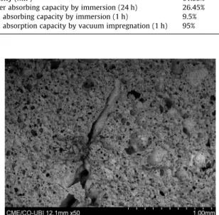
For the production of the coated PCM-LWA, commercially available and con-forming to EN 13055-1 expanded clay LWA supplied by Argex S.A were used.Table 1 shows physical properties, and chemical compositions of the LWA andFig. 1shows the microscopic images of the LWA. The numerous small and large pores can be clearly seen. The LWA was sieved to reduce it to the maximum dimensions of 8 mm. This limit was chosen to take into account the increase in radius after coating and the radius of aggregates would not be above 10 mm after coating. They were also blow dried with compressed air to remove surface dust before impregnation. Technical grade paraffin was chosen as the PCM with the following thermo-physical properties according to the producer: phase change temperature in the range of 22–26"C, thermal energy storage capacity of 230 kJ/kg, specific heat capac-ity of 2 kJ/kg K, denscapac-ity 0.77 kg/L at 40"C, thermal conductivity of 0.2 W/m K and a maximum operation temperature of 60"C. The different coating materials used are the following: commercial synthetic rubber emulsion (Sika Latex) provided by Sika S.A., commercial liquid waterproof membrane (Weber dry-lastic) supplied by Saint Gobain-Weber S.A. and polyester resin adhesive (Palatal P 4-01) combined with hardener and catalyser. The mixing ratio was determined after preparing trial mixes. The adhesive: harder: catalyser ratio that provided the most manageable working time, in this case, 15 min, was determined to be 1:0.02:0.03 by mass. Moreover, the milled carbon fibre powder (SIGRAFIL) was supplied by SLG Group and has a mean fibre length of 80 microns. Finally, the powders used to separate the LWA after coating with polyester resin were obtained directly from the quarry in the case of granite and quartz or made in the laboratory in the case of powdered glass.
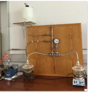
PCM was introduced into the pores of the LWA using vacuum impregnation
(Fig. 2). First a weighed sample of LWA was placed into vacuum chambers, which
were then sealed using vacuum gel. After air entrapped within the pores of the LWA were removed under a vacuum pressure of "860 mbar for 30 min. Liquid paraffin was then allowed to enter the chambers and completely submerge the LWA. The air was then allowed to enter the chambers to help force the paraffin into the pores. After this, the sample was permitted to rest for a further 30 min. An attempt was made to keep the sample at approximately 50"C during the rest stage to improve the PCM absorption as suggested by other researchers[24]. However in our experiment, only a 1.3% gain was made, so it was decided not to include this in the final impregnation process. Finally, the sample was taken out, and the surface was dried using absorbent towels to remove excess paraffin. The sample was imme-diately placed in the climatic chamber at a temperature below phase change to allow the PCM to solidify. The mass increase after impregnation and subsequent
Table 1
Physics properties and chemical composition of LWA.
Type of PCM Organic paraffin
Bulk particle density 555 kg/m3
Bulk particle SSD density 689 kg/m3
Apparent density 648 kg/m3
Bulk (tap) density 327 kg/m3
Porosity (MIP) 61.55%
Water absorbing capacity by immersion (24 h) 26.45% PCM absorbing capacity by immersion (1 h) 9.5% PCM absorption capacity by vacuum impregnation (1 h) 95%
surface drying was taken as PCM absorbing capacity of the LWA. For comparison, normal immersion of the LWA into PCM was also evaluated. However the absorp-tion capacity was a tenth of that reached using vacuum impregnaabsorp-tion (Table 1).
Table 2shows the measured PCM-LWA physical properties.
The PCM-LWA were either immersed for 5 min or sprayed with the Sikalatex and Weber lastic coating materials and then subjected to curing regimes of dry-ing in a revolvdry-ing mechanical drum, laid flat on a metal net in ambient air or the climatic chamber. In the case of the Palatal coating, it was poured over the PCM-LWA and mixed with a plastic spatula for 3 min. All of the combinations of coating and drying regimes investigated in this research can be seen inTable 3.
The Palatal – powder coating was further modified with carbon-based nanoma-terials. One type of modification was by incorporation of milled carbon fibres (CF) into the coating during the mixing of resin. The CF was incorporated at 10 wt% of resin. Before the filler material could be effectively used, its surface had to be trea-ted with silane to improve the dispersion and bonding to the resin. The silane used was hexamethyldisilazane supplied by Sigma-Aldrich and was used as 3 wt% of CF. The second type of modification was done by spraying the resin coatings with graphite spray (GS).
2.2. Geopolymer mix design and materials
For the synthesis of the geopolymer binder, the principal solid reactant used was an aluminosilicate rich mud (WM) obtained from the mining of tungsten. 20 wt% of the WM was replaced with milled glass powder (MG) to increase the overall SiO2content. This percentage replacement of WM with MG was chosen as
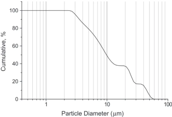
it has been previously determined to provide the most suitable workability/ strength ratio. The chemical composition and SEM images of the waste mud and milled glass are given inTable 4andFig. 3respectively. The size distribution of waste mud is described by the sieve curve given inFig. 4and obtained using a laser scattering particle size distribution analyzer (Horiba LA-920) at a circulation speed of 6 and 1 min of ultrasonic agitation to prevent the particles from agglomerating. The mud was dried, milled and sieved to a particle size below 500lm. A combina-tion of sodium hydroxide solucombina-tion (SH) and sodium silicate solucombina-tion (SS) was used as the alkaline activators. Analytical grade SH in pellets form with 98% purity (José Manuel Gomes Dos Santos, LDA) and SS with Na2O = 4.79%, SiO2 = 15.5%, and 35% water by mass (Solvay Portugal SA) was used. SH was used for the activation because it is widely available and less expensive than potassium hydroxide.
A total of 5 mixes were designed for this study (seeTable 5). Mix 1 was made as a reference and is a Portland cement mortar (PC) of known thermal conductivity. Mix 2 is a pure geopolymeric binder (GP) without any aggregates, and all the other mixes are GP containing 20 wt% resin-granite powder coated PCM-LWA (i.e. ME-LWA), coated using method 14 fromTable 3. Mix 3 contains ME-LWA without any modification ME-LWA), mix 4 contains ME-LWA with CF nanofiller CF) and mix 5 contains ME-LWA with GS modification (GP-ME-LWA-GS). All mixes were made with a constant SS/SH and precursor/activator by the mass ratio of 4 and 3 respectively.
Fig. 2. Vacuum impregnation system.
Table 2
PCM-LWA physical properties.
Apparent density 1328 kg/m3
Bulk SSD density 1326 kg/m3
Bulk density 1318 kg/m3
Bulk (tap) density 838 kg/m3
Water absorbing capacity (24 h) 0.055%
Table 3
Coating combinations and drying regimes. Coating material LWA coating method Number of coatings Drying regime
1 Sikalatex Immersion 1 Net
2 Sikalatex Immersion 1 Drum
3 Sikalatex Spray 1 Net
4 Sika latex Immersion 2 1st coating – net 2nd coating – drum
5 Sikalatex Immersion 1 Fridge
6 Weber dry-lastic Immersion 1 Net 7 Weber dry-lastic Immersion 1 Drum 8 Weber dry-lastic Immersion 2 Net
9 Weber dry-lastic Spray 1 Net
10 Weber dry-lastic Immersion 1 Fridge
11 Palatal Immersion 1 Net
12 Palatal Immersion 1 Drum
13 Palatal – powder Immersion 1 Drum 14 Palatal – powder Immersion 2 Drum
Table 4
Chemical composition (by wt%) of waste mud and milled glass.
Chemical compound Waste mud (%) Milled glass (%)
SiO2 47.66 73.93 CaO 0.00 12.83 Al2O3 19.56 0.00 Fe2O3 12.6 0.00 SO3 11.63 0.00 K2O 3.85 0.69 Na2O 1.41 9.72
a
b
10 µmFig. 3. Microscopic images of (a) tungsten mining waste mud (b) milled glass #2000.
2.2.1. Panel preparation
The mud waste powder and glass powder were firstly mixed in a dry state for 1 min. The activators were mixed using a magnetic stirrer for 5 min at 400RPM. The dry powder mixture (i.e. waste mud and glass) and activator solution were combined in a bench top mixer and mixed using at a low speed for 2.5 min and another 2.5 min at high speed. Finally, the ME-LWA were added as the last compo-nent and mixed by hand to avoid damaging them during the mixing process. The mix was poured into 150 # 150 # 30 mm3moulds and vibrated for 30 s. The mixes
were sealed to prevent moisture loss and placed in the oven at 60"C for 24 h to ini-tiate geopolymerization. After curing in the oven, the samples were demoulded and left to cure in ambient laboratory conditions until testing of the thermal conductiv-ity at 7 days.
2.3. Characterisation techniques 2.3.1. Pore structure
Mercury Intrusion Porosimetry (MIP) technique was used to determine the pore structure and porosity of the raw materials and LWA with an AutoPore IV 9500 (Micrometrics Instrument Corporation). The intrusion accuracy of the AutoPore IV 9500 was ±1% of full-scale intrusion volume.
2.3.2. Phase change behaviour
Differential scanning calorimetry (DSC) analysis was used to evaluate phase changing behaviour i.e. phase change temperature and thermal energy storage. The ME-LWA was crushed to a coarse powder, which was used to conduct the DSC test on a Q2000 (TA Instruments). The DSC samples weight was approximately 10 mg, and the temperature heating/cooling rate was 5"C/min measuring at a tem-perature range of 10–65"C.
2.3.3. Chemical properties
The pH value of the ME-LWA was measured to determine if it could interfere with the high alkaline environment of the geopolymer binder. The coated ME-LWA was ground to a fine powder-slurry using an automatic pestle and mortar, mixed with deionised water at a ratio of 1:20 and then left stirred for 12 h at 500RPM. The mixture was then filtered through 8-lm retention filter paper, and the pH of the filtered liquid was measured using HI5222 bench top pH metre.
2.3.4. Thermal conductivity
The thermal conductivity of cement mortar and geopolymer paste with and without ME-LWA was measured on 150 # 150 # 30 mm3samples at 7 days. The
apparatus used was a Netzsch HFM 436 Lambda (Netzsch Gerätebau GmbH) heat flow metre with a hot plate and cold plate set at 35 and 15"C respectively. The mean temperature of the sample was 25"C so measurement could be made at the PCMs phase change temperature. The surface of the samples was not com-pletely plane therefore thin felt strips were placed around the border of the samples to create a better seal between the testing plates.
2.3.5. Microstructure analysis
For the characterisation and analysis of the surface morphology and microstruc-ture of the raw materials, GP and its composite materials, a Zeiss Supra 35VP type scanning electron microscope was used with 20 kV energy and secondary electrons. The specimens were first coated with a 12 nm layer of gold and then analysed by SEM.
2.3.6. Strength testing
To determine the effect of the ME-LWA incorporation in GP on compressive strength, 40-mm cubes of GP and GP-ME-LWA mixes were tested at 3, 7, 14 and 28 days. The test was performed in accordance to BS EN 197-1:2011 using a 3000kN BS EN compression machine.
3. Results and discussions 3.1. Coating material and method 3.1.1. Sikalatex
In its natural state, this coating was very liquid hence all of the layers of a coating made from it were very thin (Fig. 5a–c). Even when two layers were applied, it could still be removed with light rubbing between the fingers (Fig. 5a). In previous research[24], this coating material has been used in a thickened form to coat LWA. However this could not be replicated since the details of how this was accomplished were not stated in the study. All efforts were made to separate the coated PCM-LWA while drying on the net. However, a large proportion would remain stuck together. After the coating was dry, aggregates that were stuck together had to be pulled apart causing a portion of the coating to be removed and, therefore, allowing the PCM-LWA to leak (Fig. 5c). When placed dry in the drum, the problem of aggregates sticking together during drying was eliminated, however, led to them reducing in size. The size reduction was due to the constant parti-cle collisions that slowly chipped away pieces of the LWA causing the PCM to leak out shown inFig. 5d.
3.1.2. Weber dry-lastic
The application of this coating material enabled a thicker layer of coating to be applied however the problem of particles sticking together while drying on a net could not be eliminated (seeFig. 6a). The drying of this material in the drum resulted in the aggregates not only sticking to each other but also to the wall of the drum (see
Fig. 6b). Finally, this coating material could not be applied as a spray since it was of a very thick consistency and diluting it was not an option due to its incompatibility with water.
3.1.3. Palatal
This polyester resin coating produced a smooth and hard layer around the PCM-LWA. Its curing speed was only 15 min making it the quickest out of the three coating materials tested. When dry-ing on the net, particles tended to stick together and to separate them after curing caused a brittle fracture of the aggregates (see
Fig. 7).
3.1.4. Palatal-powder
To separate the particles during curing, the granite, quartz and glass powders were chosen to be sprinkled over the PCM-LWA immediately after coating with resin and shaken manually in a drum. The powder that provided the best separation and most
0 0 1 0 1 1 0 20 40 60 80 100 Cumulative, % Particle Diameter (µm)
Fig. 4. Sieve curve of waste mud used for production of the geopolymer.
Table 5
Mix design formulation for cement mortar and geopolymer.
ID PC GP GP-ME-LWA GP-ME-LWA-CF GP-ME-LWA-GS Cement (kg/m3) 364.3 0 0 0 0 Sand (kg/m3) 979 0 0 0 0 Water (kg/m3) 165.3 0 0 0 0 WM (kg/m3) 0 1642 1313 1313 1313 MG (kg/m3) 0 337 269 269 269 SS (kg/m3) 0 527 422 422 422 SH (kg/m3) 0 131 105 105 105 Aggregates (kg/m3) 0 0 201 211 203 Water/cement 0.45 0 0 0 S.S/S.H mass ration 0 4.0 4.0 4.0 4.0 Precursor/activator mass ratio 0 3.0 3.0 3.0 3.0
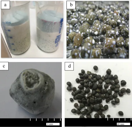
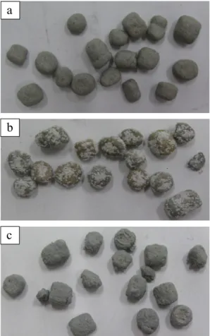
uniform coating was the granite powder(seeFig. 8a). Quartz pow-der tended to clump together and was easy to dislodge (seeFig. 8b) while the glass powder a rough textured surface (seeFig. 8c). Using granite powder under 500 micron for the first layer and powder under 250
l
m only for the second layer produced a coating with the best appearance, shown in Fig. 6a, and sealing quality, explained in Section3.2.The Palatal-powder coating process provided the most satisfac-tory results with respect to ease of coating and the speed of curing therefore only this coating was investigated further for its PCM retention capacity, chemical stability, thermal conductivity and compatibility in a geopolymeric binder, all of which are described in the following sections. The impregnation and coating process can be seen inFig. 9. Images 1–2 show the LWA being sieved and loaded into the vacuum chambers. Images 3–4 show the LWA
.
4 mm 40 mma
b
d
c
Fig. 5. PCM-LWA (a) Sikalatex immersion process (b) coated using Sikalatex drying on net (c) separated after coating using Sikalatex (d) coated using Sikaltex after drying in the drum.
a
b
Fig. 6. PCM-LWA (a) agglomeration after coating using Weber dry-lastic (b) separated after coating using Weber dry-lastic.
submerged in the PCM after impregnation and subsequent drying of the surface. Images 5–6 show the coating of the LWA and finally images 7–8 show the drum used for agitating the aggregates in granite powder and the final ME-LWA product respectfully. After impregnation, resin-granite powder coated LWA are referred to as macro encapsulated lightweight aggregates (ME-LWAs). 3.2. Impregnation and PCM retention
To determine the loss of PCM, the ME-LWA were heated at 50"C in the oven for 500 h, and the measured mass loss was only 2.99% by weight of sample shown inFig. 10. However it is not expected that the ME-LWA would be exposed to such elevated temperatures since the phase change temperature, and the maximum opera-tional temperature of this particular PCM is 25"C and 65 "C, respectively. Therefore, when left in more realistic ambient labora-tory conditions (approx. 25"C) the mass loss was only 1.11% as shown inFig. 11. The principle reason for the loss in mass can be due to small connected pores that formed during the coating pro-cess. It can be seen in the electron mapping image of the Palatal and granite powder coating inFig. 12the resin that is represented in red, does not form a continuous seal around the aggregate and small interconnected channels exist, allowing for a small percent-age (<3%) of the PCM to leak out. A part of this mass loss can also be attributed to the loss of the powder coating during the transfer between containers during mass measurement that was observed visually. The average thickness of coating achieved using the coat-ing procedure described in Section3was 0.8 mm, and it can be concluded that this is sufficient to prevent loss of PCM.
3.3. SEM
Fig. 12shows more clearly the resin and granite powder distri-bution through the electron mapping function in EDS. FromFigs. 13 and 14it can also be seen that the distribution of granite grains in the resin coating is in two layers. The combined large and small granite crystals that were used during the first coating process can be observed closer to the inner circumference of the coating, and smaller crystals used only during the second coating process appear at the outer circumference. The intention was to fill the
b
c
a
Fig. 8. Powders used to separate the ME-LWA (a) granite powder (b) quartz powder (c) glass powder.
1
2
3
4
5
6
7
8
Fig. 9. Impregnation and coating process of ME-LWA.
0 100 200 300 400 500 95 96 97 98 99 100 mass loss (%) time (hours) 50°
interstitial space between the larger crystals with smaller crystals to create a more efficient barrier against PCM leakage, which according to the mass loss curves, has been achieved.
The SEM micrograph of the ME-LWA is shown inFig. 13. It can be seen from this figure that the contact or bond between the impregnated LWA and layer of coating is well-developed in the composite mortar. The granite powder used to separate the aggre-gates during coating was also intended to increase the roughness of the surface, helping the ME-LWA interlock with the geopolymer matrix during hardening and provides better aggregate-paste bond strength. However, it can be seen fromFig. 14that some voids exist between the ME-LWA and GP matrix. The thickness of the coating is uniform and measures approximately 0.8 mm fromFig. 14which is sufficient to contain the PCM within the pores of the ME-LWA.
Fig. 15reveals some flaws at the PCM-LWA and resin-granite pow-der coating interface.Fig. 15a shows a pore within the resin and
Fig. 15b shows a fissure leading from PCM-LWA across the resin coating. These may be responsible for the small loss of PCM from the ME-LWA discussed in Section3.2.
3.4. Chemical stability and DSC of ME-LWA
The pH value of the ground ME-LWA was determined to be 7.37, making it chemically stable and neutral. This is a favourable result since it means the ME-LWA would not interfere with the highly alkaline environment of the geopolymer.
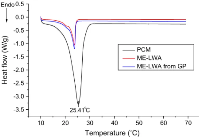
The phase change temperature can be viewed as having three main stages i.e. onset, offset and peak temperature. The starting and ending temperatures are found by intersecting the baseline and taking the tangent to the left and right respectively of the DSC curve while the peak temperature represents the peak point of the DSC curve. FromFig. 16, the onset, offset and peak temper-atures were found to be 24.49"C, 21.16 "C and 25.41 "C for RT25, which is the same value given in the manufacturers data sheet. For ME-LWA, the values were 24.76"C, 23.80 "C and 25.76 "C respectively. In a previous study by Zhang et al.[24]a significant
0 20 40 60 80 100 120 97.0 97.2 97.4 97.6 97.8 98.0 98.2 98.4 98.6 98.8 99.0 99.2 99.4 99.6 99.8 100.0 mass loss (%) time (hours) ambient
Fig. 11. PCM mass loss curve at ambient conditions.
resin LWA
GP matrix
Fig. 12. SEM image of the ME-LWA coating using electron mapping.
LWA
GP matrix Resin-powder coating
Fig. 13. SEM image of ME-LWA embedded In GP.
Fig. 14. SEM image of the ME-LWA coating.
Fissure
Pore
a
b
Fig. 15. SEM images showing (a) pores (b) fissures in the PCM-LWA and resin-granite powder coating interface.
increase in the phase change ending temperature was found between the pure PCM and an expanded clay lightweight aggre-gate impregnated with the PCM. However in this study, such a relationship was not identified – the phase change melting tem-perature for the ME-LWA was only 0.65"C lower than that of pure RT25 PCM while the crystallisation temperatures of both are almost the same.
The latent heat of melting (Hm) is calculated automatically by
the DSC software by integrating the area between the baseline and the DSC curve. The Hmfor the RT25 PCM in its pure state is
130.5 J/g while, for this PCM impregnated in the ME-LWA, it is 57.93 J/g. It is important to note here that the value for latent heat of the ME-LWA is dependent on the absorption capacity of the host material, in this case, the expanded clay aggregate (LWA). In this research, the absorption capacity of PCM to LWA is 95 wt% based on the vacuum impregnation test. Thus, if the mean latent heat of the PCM is 165 J/g (198.9 and 130.5 J/g for freezing and melting respectively), the latent heat of ME-LWA is about 157 J/g. The lower thermal conductivity and intricate pore structure of the ME-LWA affect the heat transfer efficiency to the PCM inside the pore space during melting, decreasing the energy storage density of the system to pure PCM. Nonetheless, the performance of this ME-LWA stands out when compared to other PCM composite materials developed by other researchers. For example, a form-stable PCM composite material made by incorporating dodecyl alcohol into ground gran-ulated blast furnace slag also through vacuum impregnation only achieved 22.51 J/g[25], while the specific latent heat of melting achieved for a Paraffin-Kaolin composite was only 27.88 J/g[26]. Finally, the overall heat storage capacity achieved by commercial microencapsulated PCM is approximately 51 J/g when used in sur-face cooling systems and 55 J/g for the stabilisation of indoor tem-perature in the comfort zone[27]. These values are very close to the PCM-LWA composite developed in this research, further supporting its potential to be used in heat storage applications.
The heat flow curve for the ME-LWA randomly extracted from a tested GP panel sample very closely matches that of an unused ME-LWA indicating that the thermal properties of the ME-ME-LWA are not chemically altered when added to the GP matrix. This can also allow us to assume qualitatively the ME-LWA remains damage free, and the resin-granite powder coating has an adequate impact resistance to stop the PCM from leaking out.
3.5. Thermal conductivity
The thermal conductivity of modified and non-modified ME-LWA is shown inTable 6. The effect of the different ME-LWA on thermal conductivity of GP is provided inTable 7. Compared to the LWA, the thermal conductivity of ME-LWA shows an
improvement of almost 42%. The modification of the coating layer with CF did not show any improvement in thermal conductivity as using 10% by weight of the resin was not enough to create a con-ductive link with the PCM.Fig. 17shows a few of the CF’s embed-ded in the coating. However, the number of CF’s viewed using the SEM was low. CF’s effectiveness in improving the thermal conduc-tivity of resin has been proved in loadings of 40% and above. Using a quantity larger than 10% could not be achieved due to the increased CF filler aggregation as well as dramatically increased
10 20 30 40 50 60 70 -3.5 -3.0 -2.5 -2.0 -1.5 -1.0 -0.5 0.0 0.5 Heat flow (W/g) Temperature (°C) PCM ME-LWA ME-LWA from GP 25.41°C Endo
Fig. 16. DSC curves of PCM, ME-LWA and ME-LWA extracted from GP.
Table 6
values of thermal conductivity of coated aggregates with and without modification.
ID Thermal conductivity (W/m K) LWA 0.0974 ME-LWA 0.1382 ME-LWA-CF 0.1382 ME-LWA-GS 0.1337 Table 7
values of thermal conductivity at 7 days of mixes fromTable 4.
ID Thermal conductivity (W/m K) PC 0.388 GP 0.288 GP-ME-LWA 0.211 GP-ME-LWA-CF 0.225 GP-ME-LWA-GS 0.203
CF
CF
Fig. 17. CF embedded in the resin-granite powder coating.
3 days 7 days 14 days 28days
2 4 6 8 10 12 14 16 18 20 22 24 Compressive strength (MPa) curing age GP GP with ME-LWA
viscosity, making the resin unworkable for its application to the LWA. In the case of GS, a small reduction in thermal conductivity was measured. Its ineffectiveness in creating heat conductive chains could be due to the spray nature of its application and gra-phite particles rubbing off during the GP-ME-LWA mixing process. The thermal conductivity of geopolymer with ME-LWA is lower than that of ordinary cement mortar. The composition of the ME-LWA is more diverse than that of common minerals found in nor-mal weight fine aggregate. The granite powder used in the coating of LWA has a high thermal conductivity of 3.1 W/m K and helps to balance out the low thermal conductivity of the LWA and PCM, 0.0974 and 0.2 W/m K respectively. The size of the ME-LWA used in the GP panel preparation is in the 2–10 mm range while sand used in the PC panel is 0–2 mm. This is also a contributing factor in the reduction of the thermal conductivity of GP.
3.6. Geopolymer compressive strength
The compressive strength of GP with and without ME-LWA was obtained through the cube crushing test performed in accordance with BS EN 197. Three 40-mm cubes were tested for both mixes at four different curing ages (i.e. 3-day, 7-day, 14-day and 28-day). It is evident from the results summarised inFig. 18that, at a given age, compressive strengths of GP reduced with the inclu-sion of ME-LWA. Only at 3-day strength did the GP-ME-LWA mix exceed GP in compressive strength. Visual observations of the frac-tured samples showed that the fracture occurred through the GP and not through the ME-LWA indicating that the GP binder is the weaker constituent of the ME-LWA and GP composite.
The decrease in compressive strengths observed for GP with ME-LWA can be attributed firstly to the porous nature of the LWA, making them inherently weaker in compression than normal weight coarse aggregate. Secondly, the GP-ME-LWA mix contained ME-LWA in the 2–10 mm particle size range without any fines to improve the packing efficiency of the aggregates also possibly con-tributing to the reduced strength. Thirdly, some voids appear at the interface between the GP matrix and ME-LWA as seen inFig. 14
indicating a potential zone of weakness. A reduction in compres-sive strength has also been reported in Portland cement mortars containing PCM impregnated expanded clay aggregates[28]. 4. Conclusion
Fabrication method and performance of macro encapsulated PCM made from organic paraffin and expanded clay lightweight aggregates, along with their compatibility in a geopolymeric bin-der are presented in this research, from which the following con-clusions can be made.
! Paraffin, an organic PCM with an approximate melting temper-ature of 25"C has been evaluated to be compatible for the use in impregnation of expanded clay lightweight aggregate in the 2– 10 mm size range. The low cost, abundance and wide availabil-ity of technical grade paraffin are also very beneficial.
! Vacuum impregnation and coating procedures benefit from easy preparation and can be performed for desirable aggregate dimensions.
! Out of the three different coating materials tested, the polyester resin was determined to be the most suitable choice of coating material for the PCM impregnated lightweight aggregates. Also, granite powder under 500 microns was determined to be the most suitable powder for the separation of aggregates during the resin coating process. Its sealing performance was evaluated at elevated temperatures for over 500 h with minor mass loss, rendering it practically leak proof.
! The phase change melting and solidification temperatures of PCM are not affected due to impregnation. The final macro encapsulated phase changing composite has shown to have a heat storage capacity similar to that of commercialised PCM impregnated products.
! The resin and granite powder-coated aggregates showed a 42% higher thermal conductivity than that of the aggregates in their raw state. Modification of the resin coating with milled carbon fibres or graphite spray did not lead to an improvement in ther-mal conductivity.
! The resin and granite powder-coated aggregates generally reduced the compressive strength of the geopolymeric binder. The physical interaction between the aggregate and geopolymer should be further studied.
! The neutral pH of the impregnated and coated aggregates means they would not interfere with the highly alkaline envi-ronment of the geopolymeric binder which is desirable. ! The thermal energy storing macro-encapsulated aggregates
were for the first time successfully incorporated into a geopoly-mer binder, creating a novel composite material, opening a wide selection of applications for its inclusion e.g. surface cool-ing systems, construction materials such as wallboards and ceil-ing tiles, roads and pavements.
Acknowledgement
Partial finance support from the European Commission Horizon 2020 MARIE Skłodowska-CURIE Research and Innovation Staff Exchange Scheme through the grant 645696 (i.e. REMINE project) is greatly acknowledged. The first author thanks, Brunel University London and Thomas Gerald Gray Charitable Trust for providing fees and bursary to support his PhD study. The authors also thank J. Bento at the University of Beira Interior for technical assistance. References
[1]D. Zhang, Z. Li, J. Zhou, K. Wu, Development of thermal energy storage
concrete, Cem. Concr. Res. 34 (6) (2004) 927–934.
[2]V.V. Tyagi, D. Buddhi, PCM thermal storage in buildings: a state of art, Renew.
Sustain. Energy Rev. 11 (6) (2007) 1146–1166.
[3]L.F. Cabeza, C. Castellón, M. Nogués, M. Medrano, R. Leppers, O. Zubillaga, Use
of microencapsulated PCM in concrete walls for energy savings, Energy Build.
39 (2) (2007) 113–119.
[4]G. Kanagaraj, A. Mahalingam, Designing energy efficient commercial buildings
– A systems framework, Energy Build. 43 (9) (2011) 2329–2343.
[5] T.W. Programme, P. Portal, EN H ORIZON 2020 W ORK P ROGRAMME 2014– 2015 10. Secure, clean and efficient energy Revised (European Commission Decision C (2015) 2453 of 17 April 2015), 2015, no. April, 2015.
[6]S.A. Memon, T.Y. Lo, H. Cui, S. Barbhuiya, Preparation, characterization and
thermal properties of dodecanol/cement as novel form-stable composite phase
change material, Energy Build. 66 (2013) 697–705.
[7]R. Shadnia, L. Zhang, P. Li, Experimental study of geopolymer mortar with
incorporated PCM, Constr. Build. Mater. 84 (2015) 95–102.
[8]A. Eddhahak-Ouni, S. Drissi, J. Colin, J. Neji, S. Care, Experimental and
multi-scale analysis of the thermal properties of Portland cement concretes embedded with microencapsulated Phase Change Materials (PCMs), Appl.
Therm. Eng. 64 (1–2) (2014) 32–39.
[9]M. Kheradmand, M. Azenha, J.L.B. de Aguiar, K.J. Krakowiak, Thermal behavior
of cement based plastering mortar containing hybrid microencapsulated phase
change materials, Energy Build. 84 (2014) 526–536.
[10] D. Feldman, D. Banu, D.W. Hawes, Development and application of organic
phase change mixtures in thermal storage gypsum wallboard, Sol. Energy
Mater. Sol. Cells 36 (2) (1995) 147–157.
[11]R.M. Dincer, Ibrahim, Thermal energy storage: systems and applications,
Second ed., 2002.
[12]M. Hadjieva, R. Stoykov, T. Filipova, Composite salt-hydrate concrete system
for building energy storage, Renew. Energy 19 (1–2) (2000) 111–115.
[13]M. Pomianowski, P. Heiselberg, R.L. Jensen, R. Cheng, Y. Zhang, A new
experimental method to determine specific heat capacity of inhomogeneous concrete material with incorporated microencapsulated-PCM, Cem. Concr.
[14]A.M. Khudhair, M.M. Farid, A review on energy conservation in building applications with thermal storage by latent heat using phase change materials,
Energy Convers. Manage. 45 (2) (2004) 263–275.
[15]L.F. Cabeza, A. Castell, C. Barreneche, A. De Gracia, A.I. Fernández, Materials
used as PCM in thermal energy storage in buildings: a review, Renew. Sustain.
Energy Rev. 15 (3) (2011) 1675–1695.
[16]M. Hunger, A.G. Entrop, I. Mandilaras, H.J.H. Brouwers, M. Founti, The behavior
of self-compacting concrete containing micro-encapsulated Phase Change
Materials, Cem. Concr. Compos. 31 (10) (2009) 731–743.
[17] S. U. S. Climates, J. Kosny, N. Shukla, A. Fallahi, Cost Analysis of Simple Phase Change Material-Enhanced Building Envelopes in, no. January, 2013.
[18]M.C.S. Nepomuceno, P.D. Silva, Experimental evaluation of cement mortars
with phase change material incorporated via lightweight expanded clay
aggregate, Constr. Build. Mater. 63 (2014) 89–96.
[19]S.A. Memon, H.Z. Cui, H. Zhang, F. Xing, Utilization of macro encapsulated
phase change materials for the development of thermal energy storage and
structural lightweight aggregate concrete, Appl. Energy 139 (2015) 43–55.
[20]Y. Cui, C. Liu, S. Hu, X. Yu, The experimental exploration of carbon nanofiber
and carbon nanotube additives on thermal behavior of phase change
materials, Sol. Energy Mater. Sol. Cells 95 (4) (2011) 1208–1212.
[21]Y.X. Fu, Z.X. He, D.C. Mo, S.S. Lu, Thermal conductivity enhancement with
different fillers for epoxy resin adhesives, Appl. Therm. Eng. 66 (1–2) (2014)
493–498.
[22]F. Frusteri, V. Leonardi, S. Vasta, G. Restuccia, Thermal conductivity
measurement of a PCM based storage system containing carbon fibers, Appl.
Therm. Eng. 25 (11–12) (2005) 1623–1633.
[23]T. Zhou, X. Wang, P. Cheng, T. Wang, D. Xiong, X. Wang, Improving the thermal
conductivity of epoxy resin by the addition of a mixture of graphite nanoplatelets and silicon carbide microparticles, Express Polym. Lett. 7 (7)
(2013) 585–594.
[24]D. Zhang, J. Zhou, K. Wu, Z. Li, Granular phase changing composites for thermal
energy storage, Sol. Energy 78 (3) (2005) 471–480.
[25]S.A. Memon, T.Y. Lo, S.A. Barbhuiya, W. Xu, Development of form-stable
composite phase change material by incorporation of dodecyl alcohol into
ground granulated blast furnace slag, Energy Build. 62 (2013) 360–367.
[26]S. Memon, W. Liao, S. Yang, H. Cui, S. Shah, Development of composite PCMs by
incorporation of paraffin into various building materials, Materials (Basel) 8
(2) (2015) 499–518.
[27] BASF, Intelligent Temperature Management for Buildings, 2009. [Online]. Available: <http://www.micronal.de/portal/basf/ien/dt.jsp?setCursor=1_
290798> (accessed: 15-Sep-2015).
[28]A.R. Sakulich, D.P. Bentz, Incorporation of phase change materials in
cementitious systems via fine lightweight aggregate, Constr. Build. Mater. 35