Journal of Engineering Science and Technology Review 9 (1) (2016) 159-166
Research Article
Influence of a Large Pillar on the Optimum Roadway Position in an Extremely Close Coal Seam
Li Yang 1.*, Zhang Shuai 1, Li Jia-zhuo 2, Yuan An-ying 1, Zhang Zhen-quan 1 and Wang Chen 3
1School of Resource and Safety Engineering, China University of Mining and Technology, Beijing, 100083, China 2 The Provincial Key Laboratory of mining effects & disasters preventing under deep mining in Anhui,
Anhui University of Science and Technology, Huainan, 232001, China 3 Graduate School of Engineering, Nagasaki University, Nagasaki, 852-8521, Japan
Received 3 November 2016; Accepted 10 January 2016
___________________________________________________________________________________________
Abstract
Based on the mining practice in an extremely close coal seam, theoretical analysis was conducted on the vertical stress distribution of the floor strata under a large coal pillar. The vertical stress distribution regulation of a No. 5 coal seam was revealed. To obtain the optimum position of the roadway that bears the supporting pressure of a large coal pillar, numerical modeling was applied to analyze the relation among the stress distribution of the roadway surrounding the rock that bears the supporting pressure of a large coal pillar, the plastic zone distribution of the roadway surrounding the rock, the surrounding rock deformation, and the roadway layout position. The theoretical calculation results of the stress value, stress variation rate, and influencing range of the stress influencing angle showed that the reasonable malposition of the No. 5 coal seam roadway was an inner malposition of 4 m. The mining practice showed the following: the layout of No. 25301 panel belt roadway at the position of the inner malposition of 4 m was reasonable, the roadway support performance was favourable without deformation, and ground pressure was not obvious. The research achievement of this study is the provision of a reference for roadway layouts under similar conditions.
Keywords: Large pillar, Extremely close coal seam, Roadway, Optimum position
___________________________________________________________________________________________
1. Introduction
The term extremely close coal seam means that the distance between two adjacent coal seams is close to or within the scope of underground mining and that the said coal seams generate an obvious mutual influence during the mining process [1]. After the upper coal seam is mined, the remaining coal pillar leads to stress concentration on the floor, especially when the distance of the coal seams is small to a certain degree. The stress concentration generates an obvious influence on the roof structure and the stress environment of the lower coal seam within the mining area and results in great difficulty in roadway maintenance, thereby seriously restricting the safety of the production process [2], [3], [4]. Yang [5] numerically simulated the bearing stress on the panel front and the stress characteristics on the gob floor in the mining process. Fang [6] indicated that a roadway rightly located under the remaining coal pillar with a small width of the upper coal seam can easily become unstable when affected by the mining process. Suchowerska [7] analyzed the influence factors on the floor deformation of the panel, mainly including pillar loading, pillar width, overburden depth, and inter-burden depth. Yavuz [8] proposed a method to estimate the cover pressure distance and the pressure distribution in the gob of flat-lying longwall panels. Hsiung [9] focused on the principle that governs multi-seam interactions. Lightfoot [10] analyzed the main factors that generate adverse multi-seam mining interactions.
Early research has mainly focused on the condition of large
coal seam distance but has not given much attention to the condition of an extremely close coal seam group, especially its influence on the roadway layout when the early underground mining technology is not yet mature, which in turn results in the remaining coal pillar having a large width [1]. Thus, theoretical analysis, numerical modeling, and other methods are applied to analyze the vertical stress distribution regulation of the floor strata under a large coal pillar. The destruction, stress, and deformation situations for roadways in different positions are investigated. A reference is provided for the reasonable layout of the panel roadway position in downward mining under the condition of an extremely close coal seam group.
2. General Information on the Project
The No. 25301 panel located in the Shaqu Mine is a longwall panel along the coal seam tendency. To the east side is the mining boundary, to the west side the north wing main roadway, to the south side the No. 25102 panel for the completion of mining, and to the north side the coal body under the No. 24302 panel gob. The target coal seam of the No. 25301 panel is the No. 5 coal seam. The average depth is 400m, the average thickness is 3.85m, and the average dip angle is 5°, the occurrence of the coal seam is steady, and fracture grows. The hardness of coal is low, and it is fragile after loading. The No. 24301 panel gob is rightly above the No. 25301 panel. The target coal seams of the No. 24301 panel are the No. 3 and No. 4 coal seams. The average thickness of the two coal seams is 4.12 m. The average distance between the No. 5 coal seam and the Nos. 3 and 4 coal seams is 5.5 m, which is classified into downward mining under the condition of extremely close coal seam [1].
J
estr
JOURNAL OFEngineering Science and Technology Review
www.jestr.org
______________
* E-mail address: liyang2026685@163.com
Journal of Engineering Science and Technology Review 9 (1) (2016) 159-166
Given that the early underground mining technology was not mature, a large coal pillar with a width of 45 m remained after the No. 24301 and No. 24302 panels were mined. Considering that the supporting pressure of a large coal pillar has a strong influence on the deformation failure characteristics and maintenance of a lower coal seam roadway, the optimum position selection of the No. 25301 belt panel is extremely significant.
3. Theoretical Analysis of the Stress Field Distribution Regulation under a Coal Pillar
3.1 Vertical Stress Field Distribution under a Large Coal Seam
According to the results of related domestic and foreign research, the load of a protection coal pillar is generated by the weight of the overlying rock (aabb) and part of the weight of the gob strata suspended at the two sides (abcd), which is transferred to the coal pillar [11], [12]. The absorbing load is shown in Figure 1.
d a a d f
f
c c
e b b e
B1 L B L
H
h δ δ δ
Fig.1. Calculation diagram of the load on the pillar
In the calculation above, the question of space is replaced with the question of the platform. Without considering the movement of the overlying strata, the occurrence of complex strata is simplified to lithostrome [12]. At the same time, the relation among caving height, mining height, and roof lithology is considered. The calculation result is as follows:
[
B LH L h h]
P=γ( + ) −( − tanδ) (1)
) 1 ( −
=M k
h (2)
where P is the total load on the coal pillar, MPa. h is the caving height of the stratum of the gob, m. k is the bulking factor of the roof, which is related to rock properties. δ is the caving angle of the overlying strata in the gob. M is the mining height, m. L is the width of the gob, m. B is the pillar width, m. a is the width of the elastic zone of the coal pillar, m. c is the width of the plastic zone of the coal pillar, m. γ is the average volume-weight of the overlying strata, kN/m3. H
is the mining depth, m.
Given a range of plastic zone at the two sides of the coal pillar, the fringe effect at the two sides is considered while calculating the actual load. The changes in the vertical stress in the plastic zone of the coal pillar are simplified into a linear relation. Thus, the ultimate load σ1 that can be
supported by the coal pillar is
[
B L L h h H]
c a
H
c a
P
/ ) tan ( 1
· δ
γ
σ + − −
+ = +
= (3)
According to elastic theory [13], the coal and rock of the coal seam floor are regarded as an even elastomer. The load on the floor from the coal pillar is simplified as a trapezoid distribution load, and its load on the floor rock strata is shown in Figure 2.
A Q
F C
z z2
E
c
c D x
z1 a+2c
a
M
Fig.2. Calculation diagram of the floor stress under a trapezoidal load
The superposition principle is applied to calculate the attached vertical stress of any point from the trapezoidal load on the surface of a semi-infinite body [12], [14]. In Figure 2, the floor stress under the trapezoidal load of the coal pillar is taken as an example to calculate the uniformly distributed load (AQDE) and triangular load (QDC, AEF) in different coordinate systems, and the attached vertical stress σz from
any point M in the floor strata through coordinate transformation is obtained. The calculation is as follows: Uniformly distributed load (AQDE):
⎥ ⎥ ⎦ ⎤ ⎢
⎢ ⎣ ⎡
+ − +
− − −
+ + −
= 2 2 2 2
i 2
zi
16 ) 1 4 4 (
) 1 4 4 ( 4 2
2 1 arctan 2
2 1 arctan
i i
i i i
i i
i i i
m m
n
m n m m
n m
n
p i
π
σ (4)
Triangle distributed load (QDC or AEF):
⎥ ⎥ ⎦ ⎤
⎢ ⎢ ⎣ ⎡
+ −
− − − −
= 2 2
j zj
) 1 (
) 1 ( ) 1 arctan (arctan
j j
j j j j j
j j
m n
n m m n m n n p
π
σ (5)
Trapezoid distributed load (AQCF):
(AQDE) zi zj(AEF) zj
z σ σ σ
σ = 㸦QDC㸧+ +
(6)
where σzi, σzj, and σz are the attached vertical stresses of point
M on the floor from uniform, triangular, and trapezoidal distributions, respectively. pi and pj are the maximum load
strengths of uniform and triangular distributions, respectively, that is, the ultimate load σ1 supported by the
coal pillar. mi is the proportion between the vertical distance
of point M and the floor and the uniform load width. ni is the
proportion between the horizontal distance of point M and uniformly distributed load center and the width of the uniformly distributed load. mj is the proportion between the
vertical distance of point M and the floor and the width of the triangular distributed load. nj is the proportion between
the horizontal distance of point M and the point when the triangular distributed load stress is zero and the width of the triangular distributed load.
The floor stress is overlaid under the trapezoidal load effect through the superposition principle to obtain the attached vertical stress σz of any point M on the floor
Journal of Engineering Science and Technology Review 9 (1) (2016) 159-166 ( ) ( ) ( ) ( ) ⎪⎭ ⎪ ⎬ ⎫ ⎥ ⎦ ⎤ ⎢ ⎣ ⎡ + + + − ⎟ ⎠ ⎞ ⎜ ⎝ ⎛ + + − + ⎟ ⎠ ⎞ ⎜ ⎝ ⎛ + + + ⎥ ⎦ ⎤ ⎢ ⎣ ⎡ + − − − ⎟ ⎠ ⎞ ⎜ ⎝ ⎛ − − + − ⎟ ⎠ ⎞ ⎜ ⎝ ⎛ + + ⎩ ⎨ ⎧ ⎥ ⎦ ⎤ ⎢ ⎣ ⎡ + − + − − − + + − = 2 2 2 2 2 2 2 2 2 2 2 2 2 1 z 4 2 2 2 2 2 arctan 2 2 2 arctan 1 2 2x a 4 2 2 2 2 2 arctan 2 2 2 arctan 1 2 2x -a 16 ) 4 4 ( ) 4 4 ( 4 2 2 arctan 2 2 arctan z x a x a z z x a z c x a c z x a x a z z x a z c x a c z a a z x a z x az z x a z x a π σ σ (7)
Given that the gravity stress of the floor strata under the condition of extremely close coal seams is much smaller than its supported attached vertical stress and that the roadway layout and panel operation of the lower coal seam are also mainly influenced by the attached vertical stress of the coal pillar, σz is the research target. Equation (7) implies
that the value of the vertical stress of any point M in the floor strata under the coal pillar is mainly determined by the influence of the horizontal distance between this point and the center line of the coal pillar, the vertical distance between this point and the coal pillar, the widths of the plastic and elastic zones of the coal pillar, and the ultimate supported load. According to the data from the Shaqu Mine, the burial depth H of the remaining coal pillar of Nos. 3 and 4 coal seams is 400 m, the gob width L is 158 m, the width of the plastic zone of the pillar c is 7 m, and the ultimate load σ1 is the indirect variable, which can be substituted into
Equation (7) to obtain the vertical stress concentration factor of the floor strata under the coal pillar σz/γH, that is,
( ) ( ) ( ) ( ) ⎭⎬ ⎫ ⎥⎦ ⎤ ⎢⎣ ⎡ + + + − ⎟ ⎠ ⎞ ⎜ ⎝ ⎛ + − + ⎟ ⎠ ⎞ ⎜ ⎝ ⎛ + + + ⎥⎦ ⎤ ⎢⎣ ⎡ + − − − ⎟ ⎠ ⎞ ⎜ ⎝ ⎛ − − − ⎟ ⎠ ⎞ ⎜ ⎝ ⎛ + + ⎩ ⎨ ⎧ ⎥⎦ ⎤ ⎢⎣ ⎡ + − + − − − + + − = 2 2 2 2 2 2 2 2 2 2 1 z 4 2 31 2 31 2 2 2 31 arctan 2 2 45 arctan 1 14 2x 31 4 2 31 2 31 2 2 2 31 arctan 2 2 45 arctan 1 14 2x -31 15376 ) 961 4 4 ( ) 961 4 4 ( 124 2 2 31 arctan 2 2 31 arctan z x x z z x z x z x x z z x z x z z x z x z z x z x H H πγ σ γ σ (8)
where x is the horizontal distance to the center of the coal pillar, z is the vertical distance to the floor of Nos. 3 and 4 coal seams. The vertical stress contour of the floor strata under a large coal pillar can be obtained through calculations using MATLAB, as shown in Figure 3.
-4 .2 -4.2 -4 .2 -3 .6 -3.6 -2 .9 -2.9 -2 .9 -2 .3 -2.3 -2 .3 -2 .3 -1 .6 -1.6 -1.6 -1 .6 -1 .6 -1 -1 -1 -1 -1 -1 -1 -1 -0 .8 -0 .8 -0 .8 -0 .8 -0 .8 -0 .8 -0 .8 -0 .8 -0.5 -0 .5 -0 .5 -0 .5
The distance to the center of coal pillar 㸦m㸧
Th e d is ta n ce t o t h e co a l se a m f lo o r
㸦
m
㸧
-50 -40 -30 -20 -10 0 10 20 30 40 50
-25 -20 -15 -10 -5 -4 -3.5 -3 -2.5 -2 -1.5 -1 -0.5
Fig.3. Contour map of the floor vertical stress concentration factors
under a large coal pillar
According to Figure 3, the supporting stress of a large pillar is transferred to the floor strata in accordance with a certain spreading and attenuation regulation. The stress distribution regulation of the floor strata is as follows:
If the width of the remaining coal pillar is relatively large, the vertical stress of the floor strata is distributed as “double peaks” (saddle-shaped), the peak value point of the stress will be close to the edge of the coal pillar at a certain depth, and a “valley” appears at the center of the coal pillar. Under the load, the strata within a certain range under the coal pillar include the stress concentration zone, and at the
same time, the stress constantly extends to the gob and decreases. The stress-decreasing zone is at a certain distance from the edge of the coal pillar. The concentration and decreasing zones take the stress contour of the primary rock as the boundary, and this stress contour of the primary rock is curved away from the coal pillar and slanted toward the gob floor strata at a certain depth range.
With an increase in the depth of the floor strata, the vertical stress of the strata under the coal pillar constantly decreases, the peak value also decreases and is gradually transferred to the gob zone, and the stress distribution and affecting range gradually increase, thereby resulting in spreading and attenuation. Figure 3 shows that the outstanding influence depth from the vertical stress of the floor strata is mainly concentrated within 27 m. If the depth is over 27 m, the stress change tendency gradually becomes moderate.
Given that the average distance between the No. 5 coal seam and Nos. 3 and 4 coal seams is 5.5 m, the calculation formula of the vertical stress distribution of this coal seam can be obtained after substituting it into Equation (8):
( ) ( ) ( ) ( ) ⎪⎭ ⎪ ⎬ ⎫ ⎥ ⎦ ⎤ ⎢ ⎣ ⎡ + + + − ⎟ ⎠ ⎞ ⎜ ⎝ ⎛ + − + ⎟ ⎠ ⎞ ⎜ ⎝ ⎛ + + + ⎥ ⎦ ⎤ ⎢ ⎣ ⎡ + − − − ⎟ ⎠ ⎞ ⎜ ⎝ ⎛ − − − ⎟ ⎠ ⎞ ⎜ ⎝ ⎛ + + ⎩ ⎨ ⎧ ⎥ ⎦ ⎤ ⎢ ⎣ ⎡ + − − − + + − = 121 2 31 2 31 11 11 2 31 arctan 11 2 45 arctan 1 14 2x 31 121 2 31 2 31 11 11 2 31 arctan 11 2 45 arctan 1 14 2x -31 465124 ) 840 4 ( ) 1082 4 ( 682 11 2 31 arctan 11 2 31 arctan 2 2 2 2 2 1 z x x x x x x x x x x x x H H πγ σ γ σ (9)
From Equation (9), when σz is γH, the corresponding
value of x is the position of the vertical stress of the No. 5 coal seam, which is equal to the primary rock stress, and the position of x is 4 m away from the edge of the coal pillar through calculation. Figure 4 presents the stress distribution regulation map of the No. 5 coal seam under a large coal pillar.
-40 -30 -20 -10 0 10 20 30 40 0 0.5 1 1.5 2 2.5 3 3.5
The distance to the center of coal pillar 㸦m㸧
Ve r ti c a l s tr e s s c o n c e n tr a ti o n f a c to r
Fig.4. Vertical stress distribution of the No. 5 coal seam under a large coal pillar
Journal of Engineering Science and Technology Review 9 (1) (2016) 159-166
3.2 Non-uniform Distribution Feature Analysis of Stress under Coal Pillar
Under the pressure of the coal pillar, the stress distribution differentiation of the floor under its influence is significant. Its non-uniform distribution feature is obvious, and the influencing zone is mainly concentrated at the transitory stage from the coal pillar to the gob. The uniformity of the floor stress at the section of different levels becomes moderate as the distance to the coal pillar increases. Given that the non-uniform load effect has a destructive influence on the roadway to a certain degree, the roadway should be constructed in the stress-decreasing zone, and the influence of the non-uniformity of the floor stress field on the roadway surrounding the rock structure under the coal pillar should be considered when selecting the roadway position of the lower coal seam under the condition of extremely close coal seam. The stress variation rate K is applied to measure the non-uniformity of the No. 5 coal seam vertical stress as follows:
x x d
K σz( )
= (10)
where σz(x) is the vertical stress distribution function of the
No. 5 coal pillar. x is the horizontal distance between the stress calculation point and the center of the coal pillar. Equation (10) shows that, as the non-uniformity of the vertical stress decreases, the stress variation rate K also decreases. The influence on the roadway can be solved through appropriate supporting measures when the load difference at the roof of the roadway is smaller than 25%, according to roadway characteristics and the general project design accuracy requirement, to increase the coal mining rate and reduce the coal pillar loss [15]. Thus, combined with Equation (9), the extreme position (i.e., the load difference at the roof of roadway is smaller than 25%) of the stress variation rate under different stress conditions can be obtained. The horizontal distance between this position and the edge of the coal pillar is the influence range of the non-uniformity of the vertical stress, which is 4 m.
Considering the stress value and ultimate position of the stress variation rate, combined with the facts of the remaining large coal pillar at Nos. 3 and 4 coal seams at the Shaqu Mine, the No. 25301 panel belt roadway should be arranged at the inner malposition of 4 m to the No. 24301 panel belt roadway.
4. Selection of the Optimum Position for the Roadway in the Lower Coal Seam
4.1 Calculation of the Reasonable Malposition for the Roadway
The distance between the peak value of the supporting stress and the edge of the coal pillar was obtained according to the transferring regulation of mine ground pressure in the floor strata, which is the major basis for selecting the correct position of the roadway. Thus, the roadway in the lower coal seam should be arranged outside the influencing line of the supporting stress to prevent the influence of the supporting pressure from the coal pillar in the upper coal seam; that is, a certain distance L should be kept from the coal pillar in the upper coal seam. The horizontal distance L between the roadway in the lower coal seam and the edge of the coal pillar in the upper coal seam should meet the following condition [16]:
ψ
tan ) (h1 h2
L≥ + (11)
where ψ is the stress propagation influencing angle. h 1is the
thickness of the roof of the lower coal seam, m. h 2is the
height of the roadway of the lower coal seam, m.
The horizontal malposition distance L should be larger than or equal to 4 m after the calculations under the above conditions. The No. 25301 panel belt roadway should be constructed at the inner malposition of 4 m to the roadway of the upper coal seam to reduce coal pillar loss as much as possible.
4.2 Construction of a Numerical Model
Using the geographical condition of the No. 25301 panel as the background, a 3D numerical model of fast Lagrangian analysis of the continua was constructed, as shown in Figure 5. The model size (length, width and height) was confirmed as: 280m×220m×145m, +X direction was the tendency of
the panel, +Y direction was the roadway-excavating direction, and +Z direction was the upward vertical direction. The horizontal movement was limited at the side of the model, and the vertical movement was limited at the bottom. The load on the top boundary should be calculated with a depth of 292 m, the Mohr-Coulomb model was adopted for the constitutive relation of the surrounding rock, and the side pressure factor was 1.2 according to geographical data. The designed section of the No. 25301 panel belt roadway was rectangular, with a width of 4 m and height of 3.5 m. The belt roadway was excavated along the floor of the coal seam. The detailed mechanical parameter of the strata is shown in Table 1.
The steps for numerical modeling were as follows: (1) The initial condition of the model was calculated, with given boundary mechanics and displacement condition. (2) No. 24301 roadway belt roadway and No. 24302 rail roadway were excavated one by one (after completing the No. 24301 panel operation, the No. 24302 rail roadway was excavated along the edge of the coal pillar). (3) Nos. 24301 and 24302 panels were mined one by one, and the balance was calculated. (4) No. 25301 belt roadway was excavated.
Fig.5. Three-dimensional numerical model of roadway layout under
large coal pillar
4.3 Numerical Calculation of a Reasonable Layout Position for the Roadway
Journal of Engineering Science and Technology Review 9 (1) (2016) 159-166
4.3.1 Relation between the Stress Distribution of the Roadway Surrounding the Rock and Roadway Layout Position
The deformation and destruction of the roadway surrounding the rock were closely related to some degree to the stress of
the roadway surrounding the rock [17]. The vertical stress distribution of the surrounding rock of the No. 25301 panel belt roadway is shown in Figure 6.
Table 1. Material parameter
Feature of rocks Bulk modulus /GPa Shear modulus /GPa Cohesion /MPa Internal friction angle/(º) Density /(kg·m-3
)
Tensile strength
σt/MPa
Sandy mudstone 12 10 6 38 2510 1.8
Medium sandstone 15 12 10 42 2548 3.5
No.2 coal 5 3 2 30 1309 1.5
Medium sandstone 15 12 10 42 2548 3.5
Siltstone 10 8 8 39 2430 2
No.3+No.4 coal 5 3 2 30 1313 1.5
Siltstone 10 8 8 39 2430 2
Mudstone 8 6 3.5 35 2518 1.6
No.5 coal 5 3 2 26 1310 1.5
Medium sandstone 15 12 10 42 2548 3.5
Mudstone 8 6 3.5 35 2534 1.6
Table. 2. The roadway layout plan of No.25301 panel
Plan 1 2 3 4
Roadway
Position/m Inner malposition of 10m Inner malposition of 8m Inner malposition of 6m Inner malposition of 4m
Plan 5 6 7 8
Roadway
Position/m Inner malposition of 2m Overlapping Outer malposition of 4m Outer malposition of 8m
Fig.6. Vertical stress distribution of different plans
From Figure 6, the stress distribution characteristics of the surrounding rocks of the No. 25301 panel roadway in different plans were obtained as follows:
The vertical stress of the roadway surrounding the rock in the outer malposition layout was the largest, that of the overlapping layout was moderate, and that of the inner malposition layout was the smallest.
The floor and roof surrounding the rock of the roadway were basically under low stress condition with the variation in roadway layout position, but the stress at the two sides of the roadway constantly changed. Thus, the stress at the two sides of the roadway was non-uniformly distributed, thereby resulting in the structural non-uniform instability deformation of the roadway-supporting structure. To address
this problem, the side with a high roadway stress concentration should be reinforced to positively adjust the non-uniform deformation of the surrounding rock and maintain the roadway.
Journal of Engineering Science and Technology Review 9 (1) (2016) 159-166
releasing zone under the gob, the vertical stress distribution is uniform, and the roadway can be maintained easily.
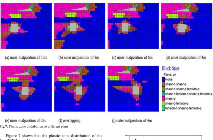
4.3.2 Relation between the Plastic Zone of the Roadway Surrounding the Rock and Roadway Layout Position The plastic zone distribution of No. 25301 panel belt roadway is shown in Figure 7.
Fig.7. Plastic zone distribution of different plans
Figure 7 shows that the plastic zone distribution of the No. 25301 panel belt roadway in different plans is obtained as follows:
The plastic zone of the roadway surrounding the rock is the outcome of shearing and tension. The deformation and destruction of the roadway roof and floor result from shearing, whereas the deformation and destruction of the two sides result from shearing and tension.
Different roadway layout positions result in different destruction features of the surrounding rock. When the outer malposition or overlapping layout is applied, the plastic destruction is serious, and the destruction range near the gob side is large. The shearing stress is concentrated close to the gob side and remains in the affecting range of the supporting pressure of the large pillar. As a result, the above two problems cause serious destruction. When the overlapping layout and an inner malposition of 2 m are applied, the roof destruction zone and the gob of the upper panel are connected, which easily leads to caving accidents of a large area of the roof. When an inner malposition of 4 m is applied, the plastic-destruction degree of the roadway is low, and the destruction range is the smallest. As the inner malposition distance increases, the plastic destruction range increases and gradually connects to the strong shearing destruction zone of the gob floor.
4.3.3 Relation between Surrounding Rock Deformation and Roadway Layout Position
The deformation regulation of the roadway surrounding the rock is obtained by analyzing the surface displacement data of the No. 25301 panel belt roadway, as shown in Figure 8.
-10 -8 -6 -4 -2 0 2 4 6 8 10 12
0 100 200 300 400 500
Th
e c
o
n
v
er
g
en
ce
㸦
mm
㸧
The roadway layout position 㸦m㸧
㸦inner malposition as the + direction㸧
The roof-to-floor convergence The convergence at two sides
Fig.8. Deformation regulation of the roadway surrounding the rock in
different plans
From Figure 8, the deformation regulation of the surrounding rock of the No. 25301 belt roadway is as follows:
The roof-to-floor convergence rapidly decreases as the outer malposition distance decreases. When the roadway layout position changes from an outer malposition of 8 m to an overlapping layout, the roof-to-floor convergence changes from 459 mm to 120.5 mm, which represents an decrease of 74%. The roof-to-floor convergence initially decreases in a small range and slowly increases as the inner malposition distance increases. The deformation curve forms an inflection point in different layout positions; that is, when the inner malposition distance is 2 m, the smallest convergence is 42 mm.
Journal of Engineering Science and Technology Review 9 (1) (2016) 159-166
of 8 m to an inner malposition of 10 m, the largest deformation is only 33.5 mm.
In conclusion, when the roadway layout position changes from an inner malposition of 2m to an inner malposition of 6m inner malposition, the roof-to-floor convergence and the convergence at the two sides are in a reasonable range.
5. Project Practice
The layout with the inner malposition of 4 m was eventually applied on the No. 25301 panel belt roadway, which was already prepared by applying a bolt-mesh-anchor support. The No. 25301 panel layout is shown in Figure 9.
No.24301 panel rail roadway
No.25301 panel rail roadway
No.24302 panel rail roadway No.24301 panel
belt roadway
No.25301 panel belt roadway
No.24301 panel gob No.24302 panel gob
the coal pillar
L h1
h2
¦ ×
Fig.9. Profile of the No. 25301 panel
The result of monitoring the deformation of the roadway excavation and panel operation shows that, in the entire excavation period, the roof-to-floor convergence is usually from 45 mm to 80 mm and the roadway does not present deformation. In the operation process of the No. 25301 panel, the pre-influencing range on the belt roadway reaches 30 m, the accumulated roof-to-floor convergence is basically kept from 130 mm to 163 mm, the deformation rate is 3 mm/d to 7 mm/d, and the accumulated convergence at the two sides is 105 mm to 142 mm.
From the onsite monitoring data, an inner malposition of 4 m was applied on the No. 25301 panel belt roadway, and the supporting effect was favorable, and no obvious deformation and strong ground appeared. The roadway displacement curve is shown in Figure 10.
0 10 20 30 40 50 60
80 90 100 110 120 130 140 150 160 170
The roof-to-floor convergence The convergence at two sides
The accumu
lated c
on
vergence
(mm)
The distance to panel coal wall (m)
Fig.10. Displacement curve of the roadway
6. Conclusions
Based on the mining practice in an extremely close coal seam of the Shaqu Mine, by elastic theory, and given the influence of the supporting pressure distribution of a large coal pillar, a mechanical model of floor stress distribution was established. The vertical stress of the No. 5 coal seam under a large coal pillar is revealed to be distributed as “double peaks”, and the peak stress concentration factor at the edge of the coal pillar is 3.10.
Numerical modeling was applied to analyze the relation among the stress distribution of the roadway surrounding the rock bearing supporting pressure from the large coal pillar, the plastic zone distribution of the roadway surrounding the rock, the surrounding rock deformation, and the roadway layout position. The results lead to the conclusion that the roadway plastic destruction range, vertical stress, and roof convergence have the largest values in the outer malposition layout, the smallest values in the inner malposition layout, and medium values in the overlapping layout. The calculation was conducted. According to the stress value, stress variation rate, and stress influencing angle, The most reasonable layout position of the No. 25301 panel belt roadway is the inner malposition of 4 m to the panel roadway of the No. 4 coal seam.
The project practice shows that applying an inner malposition of 4 m layout on the No. 25301 panel belt roadway at the Shaqu Mine is reasonable, the support performance by applying bolt-mesh-anchor is good, no obvious deformation appears, and ground pressure is moderate. The research results provide reference for roadway layout selection under similar conditions.
Acknowledgments
The study was supported by National Key Basic Research Program of China (2014CB260403), the State Key Program of National Natural Science Foundation of China (U1361208), the National Natural Science Foundation of China (51504005, 51304007) and Anhui Provincial Natural Science Foundation (1408085MKL42).
______________________________ References
1. Zhang, B. S., Kang, L. X., Zhai, Y. D., "Definition of ultra-close multiple-seams and its ground pressure behavior", Proceedings of the 24th International Conference on Ground Control in Mining, Morgantown, WV, 2005, pp. 110-113.
2. Yan, H., Weng, M. Y., Feng R. M., "Layout and support design of a coal roadway in ultra-close multiple-seams", Journal of Central South University, 22(11), 2015, pp. 4385-4395.
3. Chen, D. M., Zhang, C. L., "Study on floor pressure relief law of simultaneous mining working faces in close distance seam group of dongsheng coalfield", Advance Materials Research, 941-944, 2014, pp. 2525-2532.
Journal of Engineering Science and Technology Review 9 (1) (2016) 159-166 5. Yang, W., Lin, B. Q., Qu, Y. A., Li, Z. W., Zhai, C., Jia, L. L., Zhao,
W. Q., "Stress evolution with time and space during mining of a coal seam", International Journal of Rock Mechanics and Mining Sciences, 48(1), 2011, pp. 1145−1152.
6. Fang X. Q., Guo, M. J., Lv, Z. Q., "Instability mechanism and prevention of roadway under close-distance seam group mining", Chinese Journal of Rock Mechanics and Engineering, 28(1), 2009, pp. 2059-2067.(in Chinese)
7. Suchowerska, A. M., Merifield, R. S., Carter, J. P., "Vertical stress changes in multi-seam mining under supercritical longwall panels" , International Journal of Rock Mechanics and Mining Sciences, 61, 2013, pp. 306−320.
8. Yavuz, H., "An estimation method for cover pressure re-establishment distance and pressure distribution in the goaf of longwall coal mines", International Journal of Rock Mechanics and Mining Sciences, 41(2), 2004, pp. 193-205.
9. Hsiung, S. M., Peng, S. S., "Design guidelines for multiple seam mining Part I ", Coal Mining, 24(9)1987, pp. 42−46.
10. Lightfoot, N., Liu, N., "The prediction of pillar interaction effects for deep multi-seam mining", Proceedings of the 29th International Conference on Ground Control in Mining, Morgantown, WV, 2010, pp. 8-16.
11. Wilson, A. H., "The stability of underground workings in the soft rocks of the coal measures", International Journal of Rock Mechanics and Mining Sciences, 1, 1983, pp. 91-187.
12. Qian, M. G., Shi, P. W., "Mine pressure and ground control", Xuzhou:China University of Mining and Technology Press, 2003, pp. 60-63. (in Chinese)
13. Wu, J. L., "Elasticity", Beijing:Higher Education Press, 2001, pp. 65-68.(in Chinese)
14. Chen, S., "Calculation of additional stresses in soil produced by infinite long ladder-shaped distribution load", Suzhou institute of urban construction and environmental protection, 7(3), 1994, pp. 29-32.(in Chinese)
15. Wu, Y. P., "Non-symmetrical load effect in roadway support design", Journal of Xi'an Mining Institute, 17(1), 1997, pp. 1-4.(in Chinese)
16. Li, Y., Qiu, B., "Investigation into key strata movement impact to over-burden movement in cemented backfill mining method", Procedia Engineering, 31, 2012, pp. 727-733.