Hazem A. Attia
Dept. of Math., College of Science Al-Qasseem University P.O. Box 237, Buraidah 81999, KSA On leave from: Dept. of Eng. Math. and physics Fac. of Eng., El-Fayoum University El-Fayoum, EgyptRotating Disk Flow and Heat Transfer
of a Conducting Non-Newtonian Fluid
with Suction-Injection and Ohmic
Heating
The steady hydromagnetic flow in a porous medium of an incompressible viscous electrically conducting non-Newtonian fluid above an infinite rotating porous disk is studied with heat transfer. An external uniform magnetic field is applied perpendicular to the disk and a uniform injection or suction is applied through the surface of the disk. Numerical solutions of the nonlinear governing equations, which govern the flow and energy transfer, are obtained. The effect of the magnetic field, the suction and injection velocity and the characteristics of the non-Newtonian fluid on the velocity and temperature distributions are considered. .
Keywords: rotating disk flow, heat transfer, numerical solution, suction-injection
Introduction
The pioneering study of fluid flow due to an infinite rotating disk was carried by von Karman (von Karman 1921). von Karman gave a formulation of the problem and then introduced his famous transformations which reduced the governing partial differential equations to ordinary differential equations. Asymptotic solutions were obtained for the reduced system of ordinary differential equations by Cochran (Cochran 1934). Their analysis was much simpler and valuable information was gained from it. This gave the problem significant theoretical value and invited many researchers to add to it new features. Benton (1960) improved Cochran's solutions and solved the unsteady problem and proved that the steady state solution can be obtained via a time-dependent process.
In recent years, considerable interest has been shown in mass addition to boundary layer flows, especially in connection with the cooling of turbine blades and the skins of high speed aero-vehicles. Such a cooling process, frequently termed transpiration, might utilize a porous surface through which a coolant, either a gas or liquid, is forced. It is of interest to study the effect of the magnetic field as well as the non-Newtonian fluid behavior on the heat transfer and, in turn, on the cooling process of such devices. These results are needed for the design of the wall and the cooling arrangements.1
The problem of heat transfer from a rotating disk maintained at a constant temperature was first considered by Millsaps and Pohlhausen (1952) for a variety of Prandtl numbers in the steady state. Sparrow and Gregg (1960) studied the steady state heat transfer from a rotating disk maintained at a constant temperature to fluids at any Prandtl number. Later Attia (1998) extended the problem discussed in (Millsaps et al. 1952, Sparrow et al. 1960) to the unsteady state in the presence of an applied uniform magnetic field where a numerical solution has been obtained for the governing equations.
The steady flow of Reiner-Rivlin non-Newtonian fluid due to a rotating disk with uniform suction was considered by Mithal (1961). The solutions obtained were valid for small values of the parameter which describes the non-Newtonian behavior. Then, Attia (2003) extended the problem to the transient state with heat transfer and obtained a numerical solution for the governing non-linear equations which is valid for the whole range of the non-Newtonian parameter.
The hydromagnetic flow due to a rotating disk was studied in the presence of an external uniform magnetic field (El-Mistikawy et
Paper accepted September, 2006. Technical Editor: Monica F. Naccache
al. 1990, 1991). Steady state asymptotic solutions for strong (El-Mistikawy et al. 1990) and weak (El-(El-Mistikawy et al. 1991) magnetic fields were obtained. Aboul-Hassan and Attia (1997) studied the steady hydromagnetic problem taking the Hall effect into consideration and a numerical solution for the governing equations was obtained. The effect of the ion slip on the steady hydromagnetic flow with heat transfer was studied by Attia (2003).
The effect of a uniform suction or injection through a rotating porous disk on the steady hydrodynamic flow induced by the disk was investigated (Stuart 1954, Ockendon 1972, Kuiken 1971). Stuart (1954) introduced suction through the disk and solved the governing equations with zero rotation at infinity. Ockendon (1972) used asymptotic methods to determine the solution of the problem for small values of the suction parameter and in the case of rotation at infinity. The effect of uniform injection through a rotating porous disk on the flow induced by the disk was studied by Kuiken (1971). Later Attia extended the problem to the case of an unsteady hydromagnetic flow in the presence of an external uniform magnetic field without considering the Hall effect (1998). The effect of uniform suction or injection on the flow of a conducting fluid due to a rotating disk was studied in the presence of a uniform magnetic field with the Hall current (Attia et al. 2001).
In the present work, the steady hydromagnetic laminar flow with heat transfer of an incompressible viscous electrically conducting non-Newtonian fluid due to the uniform rotation of a porous disk of infinite extent in an axial uniform steady magnetic field is studied considering the Ohmic heating. A uniform injection or suction is applied through the surface of the disk. The temperature of the disk is maintained at a constant value. The governing nonlinear differential equations are integrated numerically using the finite difference approximations. The effect of the magnetic field, the characteristics of the non-Newtonian fluid and the suction or injection velocity on the steady flow and heat transfer is presented and discussed.
Nomenclature
Bo = magnetic flux density
i j
e = strain tensor
Ec = Eckert number
(F, G, H) = non-dimensional velocity components, k = thermal conductivity,
K = non-Newtonian parameter, p = pressure gradient,
169 Pr = Prandtl number
M = magnetic parameter T = temperature of the fluid Tw = temperature of the disk,
∞
T = temperature of the ambient fluid, S = Suction parameter,
wo = vertical velocity at the disk, (u, v, w) = velocity components, (r, ϕ, z) = cylindrical coordinates,
θ = non-dimensional temperature, = viscosity of the fluid,
c
µ = coefficient of cross viscosity,
✁
= density of the fluid,
σ = electrical conductivity of the fluid, ω = angular velocity of the disk,
i j
τ = stress tensor,
ζ = non-dimensional distance.
Basic Equations
Let the disk lie in the plane z=0 and the space z>0 is occupied by an incompressible viscous Reiner-Rivlin non-Newtonian fluid as shown in Fig. 1. The motion is due to the rotation of an insulated disk of infinite extent about an axis perpendicular to its plane with constant angular speed ω. Otherwise the fluid is at rest under pressure p∞. The disk is maintained at a constant temperature Tw.
An external uniform magnetic field is applied in the z-direction and has a constant flux density Bo. The magnetic Reynolds number is
assumed to be very small, so that the induced magnetic field is negligible (Sutton et al. 1965). A uniform injection or suction is applied at the surface of the disk for the entire range from large injection velocities to large suction velocities.
The constitutive equation for the Reiner-Rivlin non-Newtonian fluid is given by Mithal (1961):
, e , p e e
eij cki kj ij ij i
j=2µ +2µ − δ =0
τ (1)
whereτij is the stress tensor, eij is the strain tensor, p is denoting
the pressure, ✂ is the coefficient of viscosity,
(
c e e)
/2 ij i j c=α +∑ ∑
µ
is the coefficient of cross viscosity, c=const., andα is a sufficiently small parameter (constant). The Reiner-Rivlin model is comparatively simple, but it provides a somewhat intuitive prediction of flow parameters and heat transfer performance of a viscoelastic fluid above a rotating disk.
Figure 1. Flow configuration.
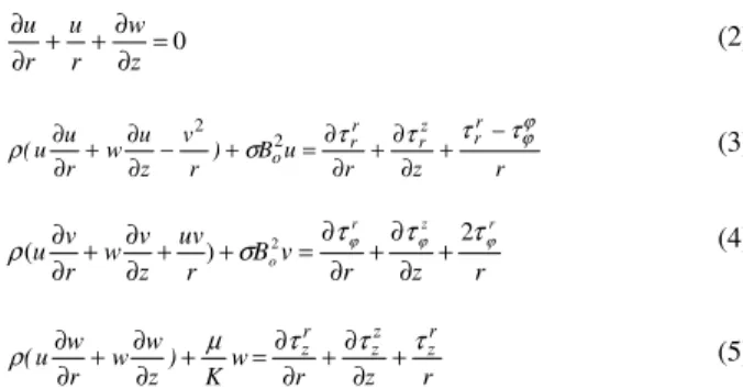
The equations of steady motion, using Eq. (1), are given by
0 = ∂ ∂ + + ∂ ∂ z w r u r u (2) r z r u B ) r v z u w r u u ( r r z r r r o ϕ ϕ τ τ τ τ σ
ρ + −
∂ ∂ + ∂ ∂ = + − ∂ ∂ + ∂
∂ 2 2 (3)
r z r v B r uv z v w r v u r z r o ϕ ϕ
ϕ τ τ
τ σ
ρ( ) 2 2
+ ∂ ∂ + ∂ ∂ = + + ∂ ∂ + ∂
∂ (4)
r z r w K ) z w w r w u ( r z z z r
z τ τ
τ µ ρ + ∂ ∂ + ∂ ∂ = + ∂ ∂ + ∂
∂ (5)
where u, v, w are velocity components in the directions of increasing r,ϕ, z respectively, ρ is the density of the fluid, and σ is the electrical conductivity of the fluid. We introduce von Karman transformations (von Karman 1921),
P v p p , / v z , H v w , G r v , F r
u= ω = ω = ω = ωζ − ∞=−ρω
whereζ is a non-dimensional distance measured along the axis of rotation, F, G, H and P are non-dimensional functions of ζ , and ν is the kinematics viscosity of the fluid, ν =µ/ρ. With these definitions, Eqs. (2)-(5) take the form
0 2 = + F d dH ζ (6) 0 2 3 2 1 2 2 2 2 2 2 2 2 = + + − − + − − ) d F d F ) d dG ( ) d dF (( K MF G F d dF H d F d ζ ζ ζ ζ ζ (7) 0 2 2 2 2 2 = − + − − − ) d G d F d dG d dF ( K MG FG d dG H d G d ζ ζ ζ ζ ζ (8) 0 2 7 2 2 2 2 = + − − ζ ζ ζ ζ ζ d dP d H d d dH K d dH H d H
d (9)
where M =σBo2/ρω is the magnetic interaction number (Sutton et
al. 1965) and K is the parameter which describes the non-Newtonian behavior, K=✂
c/✂ ✄ (Mithal 1961).
The boundary conditions for the velocity problem are given by
, S H , G , F , = = =
=0 0 1
ζ (10a)
, P , G , F
, →0 →0 →0
∞ →
ζ (10b)
where S=wo/ ων is the uniform suction or injection parameter,
which takes constant negative values for suction and constant
positive values for injection, and
w
o is the vertical velocitycomponent at the surface. Equation (10a) indicates the no-slip condition of viscous flow applied at the surface of the disk, but due to the uniform suction or injection, the vertical velocity component takes a constant non-zero value at z=0. Far from the surface of the disk, all fluid velocities must vanish aside the induced axial component as indicated in Eq. (10b). The above system of Eqs. (6)-(8) with the prescribed boundary conditions given by Eq. (10) are sufficient to solve for the three components of the flow velocity. Equation (9) can be used to solve for the pressure distribution if required.
0
1 2 2 2
2 2
2 2
= + + ∂ ∂ + ∂ ∂ + ∂ ∂ − ∂ ∂ + ∂ ∂
) v u ( B ) r T r r
T
z T ( k ) z T w r T u (
cp σ o
ρ (11)
where T is the temperature of the fluid, cp is the specific heat at
constant pressure of the fluid, and k is the thermal conductivity of the fluid. The last term in Eq. (11) represents the Ohmic heating. The boundary conditions for the energy problem are that, by continuity considerations, the temperature equals Tw at the surface
of the disk. At large distances from the disk, T tends to T where T is the temperature of the ambient fluid. In terms of the non-dimensional variable ✁
=(T-T )/(Tw-T ) and using von Karman
transformations, Eq. (11) takes the form;
0
1 2 2
2 2
= + +
+ MEc(F G ) d
d H d d
Pr ζ
θ ζ
θ (12)
where Pr is the Prandtl number given by, Pr=cp✂ /k and )
T T ( c / r
Ec=ω2 2 p w− ∞ is the Eckert number.
The boundary conditions for the temperature field are expressed as
0 1
0)= , (∞)=
( θ
θ (13)
The system of non-linear ordinary differential equations (6)-(8) and (12) is solved under the conditions given by Eq. (10) and (13) for the three components of the flow velocity and temperature distribution, using the Crank-Nicolson method (Ames 1977). The resulting system of difference equations has to be solved in the infinite domain 0<✂ <
✄
. A finite domain in the ✂ -direction can be used instead with ✂ chosen large enough to ensure that the solutions are not affected by imposing the asymptotic conditions at a finite distance. The independence of the results from the length of the finite domain and the grid density was ensured and successfully checked by various trial and error numerical experimentations. Computations are carried out for ✂ п=12 and step size ☎ ✂ =0.04 which are found adequate for the ranges of the parameters studied here. Larger finite distance or smaller step size do not show any significant change in the results. Convergence of the scheme is assumed when every one of the variables F, G, H,
✁
, dF/d✂ , dG/d✂ , and d✁
/d✂ for the last two approximations differs by less than 10 -6
for all values of ✂ in 0<✂ <12.
Results and Discussion
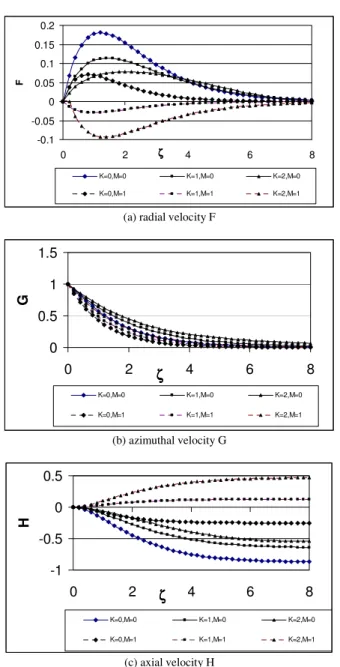
Figures 2a,b,c,d present the steady state velocity components and temperature, F, G, H, and θ, respectively, for various values of K and for M=0 and 1. In these figures, S=0, Pr=0.7 and Ec=0.2. It is clear from Fig. 2b that increasing K increases G for all ζ . Figure 2b shows also the damping effect of the magnetic field which results in a reduction in the velocity component G for all ζ . Figure 2a indicates that, for M=0, increasing the parameter K decreases F for small and moderate values of ζ . This can be attributed to the fact that increasing K decreases the axial flow towards the disk (see Fig. 2c) which, in turn, decreases the radial flow since the axial flow is diverted into radial flow. However, for larger values of ζ a crossover point that depends on K appears and an increment in K increases F. This may result from the increase in the velocity component G with increasing K which becomes more effective at larger values of ζ , as shown in Fig. 2b, and consequently result in an increase in F in this region. Figure 2a presents an interesting effect for the magnetic field in the suppression of the crossover points that appear with the variation of K. This is actually due to the
reduction in G with increasing M. Also, it is shown in Fig. 2a the influence of the magnetic field, for large values of K, in reversing the direction of the velocity component F with S=0. The magnetic field has the effect in reducing the magnitude of F for all ζ and for various values of K. Figure 2c shows that increasing the parameter K or M increases the resistance for the incoming axial flow and consequently reduces the axial velocity towards the disk H for all
ζ . For large values of K, due to the reversal of the direction of F which is the source for H, a resistance is imposed on the axial flow towards the disk and consequently the direction of H is reversed. Figure 2d indicates that increasing K or M increases θ for all ζ
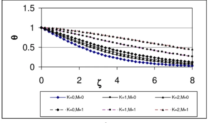
due to the effect of K or M in damping the axial flow towards the disk and, consequently, prevents bringing the fluid at a near-ambient temperature towards the surface of the disk. It is noticed that, for large values of K, the combined effect of K and M results in the diminishing of the effect of the term Hdθ/dζ in Eq. (12) and then leads to a linear dependence of θ on ζ .
-0.1 -0.05 0 0.05 0.1 0.15 0.2
0 2 ζζζζ 4 6 8
F
K=0,M=0 K=1,M=0 K=2,M=0
K=0,M=1 K=1,M=1 K=2,M=1
(a) radial velocity F
0 0.5 1 1.5
0 2 ζζζζ 4 6 8
G
K=0,M=0 K=1,M=0 K=2,M=0
K=0,M=1 K=1,M=1 K=2,M=1
(b) azimuthal velocity G
-1 -0.5 0 0.5
0 2 ζζζζ 4 6 8
H
K=0,M=0 K=1,M=0 K=2,M=0
K=0,M=1 K=1,M=1 K=2,M=1
(c) axial velocity H
Figure 2. Effect of the porosity parameter M and the non-Newtonian parameter K on the profile of: (a) radial velocity F; (b) azimuthal velocity
171
0 0.5 1 1.5
0 2 ζζζζ 4 6 8
θθθθ
K=0,M=0 K=1,M=0 K=2,M=0
K=0,M=1 K=1,M=1 K=2,M=1
(d) temperatureθ. (S=0, Pr=0.7)
Figure 2. (Continued).
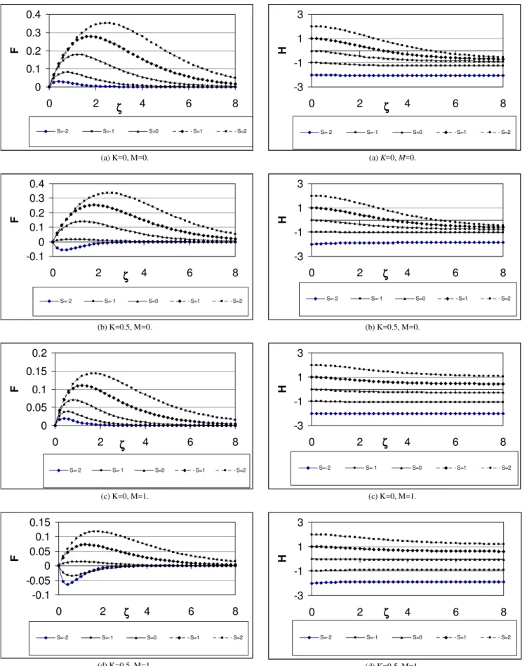
Figures 3a and 4a present the influence of the axial flow at the surface of the disk (the suction parameter S) on the steady state radial and axial velocity components F and H, respectively, with K=0 and M=0. Consider first the case of impermeable surface, S=0. The rotating disk acts as a fan, drawing fluid axially inward from the surroundings toward the surface of the disk. However, because the surface of the solid, the inflowing fluid finds its path blocked, and it must reroute into a radial direction where there is no obstruction. Therefore, we see in Fig. 4a that the negative velocity of inflow, starting from its largest value at large ζ , decreases steadily as we approach the disk (decreasing ζ ) due to fluid escape into the radial direction. Now, consider the application of a suction at the surface of the disk (S<0). Then, besides the fanlike pumping of the rotating disk, there is the additional pumping due to the suction. Therefore, the quantity of fluid drawn in from the surroundings increases. Now, the inflowing fluid has two possible paths. It may continue its inflow through the suction holes of the disk, or, it may reroute into radial direction. The path chosen will, of course, be that of least resistance. As the wall suction increases, escape through the wall becomes easier and easier. Therefore, with S becoming increasingly negative, more and more of the inflow goes directly into the porous disk. As a consequence, H tends to be almost constant with z. Next, consider the case of injection at the surface of the disk (S>0). In this instance, the fluid drawn in by the fan action of the disk finds itself actively retarded by the outflowing stream of injected flow. The greater the injection velocity, the more strongly is the inflow opposed. The result is a decrease in the magnitude of H with increasing S. There is, in a real sense, a battle between the two streams; and as S increases, the outflow penetrates to greater distances from the disk surface. As a consequence, the crossover point between positive and negative H is pushed farther outward. It is seen also that the fluid injection gives rise to the familiar inflection-point profiles, especially for high values of the injection parameter S. Then, high injection velocities are expected to destabilize the laminar flow and lead to transition to turbulence.
These events are reflected by the radial velocity distribution. Representative profiles are given in Fig. 3a. Since the radial velocity is zero both at the disk surface and in the ambient fluid, there must be a maximum value somewhere between. The maximum is positive since the radial flow is always outward along the disk. For the impermeable disk (S=0), all the axial inflow is ultimately diverted into radial flow. With increasing suction, more and more of the inflowing fluid passes directly into the porous wall; therefore, the radial velocities decrease as S becomes more negative. Further, since less fluid makes the turn from axial to radial flow, it can be accomplished closer to the surface, and hence the maximum value of F occurs at smaller distance from the disk.
When injection is applied (S>0), the radial velocity must carry away not only the incoming axial flow, but also the injected fluid. Therefore, the general level of the radial velocity is raised with increased injection.
Figure 3b presents the steady state radial velocity profile F for various values of suction or injection velocities and for K=0.5 and M=0. A comparison between Figs. 3a and 3b shows that, for the whole range of injection velocities and small suction velocities, increasing K decreases F for all ζ . When the suction velocity is large, increasing the parameter K reverses the direction of F. With K=0.5 increasing the suction velocity leads to an increment in the magnitude of F for small ζ while decreases its magnitude as ζ
increases which results in the appearance of crossover points with
ζ . The distances from the disk at which the crossover appears decreases with increasing the suction velocity. This is due to the fact that increasing the suction velocity pumps the reversed flow in the negative radial direction near the disk and increases its velocity. At a greater distances from the disk, increasing suction helps the axial flow towards the disk which stops the reversed radial flow and then decreases its velocity. The influence of the magnetic field on the steady state profiles of F is shown in Fig. 3c with K=0 and M=1 and for various values of the parameter S. The magnetic field effect is to sustain the flow in the radial direction for all values of the suction or injection velocities. However, its effect is more pronounced in the case of injection more than that in the case of suction.
Figure 3d presents the steady state radial velocity profile F for various values of suction or injection velocities and for K=0.5 and M=1. Increasing the two parameters leads to a great reduction in F for all values of the injection velocities. In the case of suction, the parameters K and M result in reversing the direction of F and increasing its magnitude for all values of the suction velocity. The figure also presents the appearance of the crossover points in F profiles due to change in the parameter S.
0
0.1
0.2
0.3
0.4
0
2
ζ
ζζ
ζ
4
6
8
F
S=-2 S=-1 S=0 S=1 S=2
(a) K=0, M=0.
-0.1
0
0.1
0.2
0.3
0.4
0
2
ζζ
ζ
ζ
4
6
8
F
S=-2 S=-1 S=0 S=1 S=2
(b) K=0.5, M=0.
0
0.05
0.1
0.15
0.2
0
2
ζζ
ζ
ζ
4
6
8
F
S=-2 S=-1 S=0 S=1 S=2
(c) K=0, M=1.
-0.1
-0.05
0
0.05
0.1
0.15
0
2
ζ
ζζ
ζ
4
6
8
F
S=-2 S=-1 S=0 S=1 S=2
(d) K=0.5, M=1.
Figure 3. The radial velocity profile vs. S.
-3
-1
1
3
0
2
ζζ
ζ
ζ
4
6
8
H
S=-2 S=-1 S=0 S=1 S=2
(a) K=0, M=0.
-3
-1
1
3
0
2
ζζ
ζ
ζ
4
6
8
H
S=-2 S=-1 S=0 S=1 S=2
(b) K=0.5, M=0.
-3
-1
1
3
0
2
ζζ
ζ
ζ
4
6
8
H
S=-2 S=-1 S=0 S=1 S=2
(c) K=0, M=1.
-3
-1
1
3
0
2
ζζ
ζ
ζ
4
6
8
H
S=-2 S=-1 S=0 S=1 S=2
(d) K=0.5, M=1.
173 Conclusions
In this study the steady hydromagnetic flow of a conducting non-Newtonian fluid induced by a rotating disk with heat transfer was studied in the presence of uniform suction and injection. The effect of the magnetic field of the medium, the non-Newtonian fluid characteristics and the uniform suction or injection velocity on the velocity and temperature distributions was considered. An interesting result is the effect of the parameter K in reversing the direction of the radial velocity for large suction velocities in the non-magnetic case. It is also of interest to see the influence of both parameters K and M in reversing the direction of the radial flow for all suction velocities and even in the case of zero suction velocity. One more effect for the magnetic field is to suppress the crossover occurs in the radial velocity profiles due to the variation of K. The magnetic field works to stabilize the flow while the non-Newtonian fluid characteristics tends to destabilize the flow.
The magnetic field has a more pronounced effect on the flow in the case of injection than suction and its effect can be neglected for large suction velocities. On the other hand, the non-Newtonian characteristics has an apparent effect on the flow for all values of suction or injection velocities while its effect on the flow in the case of suction is more pronounced than the case of injection. Therefore, the two parameters K and M together have an apparent effect on the flow for the whole range of the axial velocity at the surface of the disk. The non-Newtonian fluid characteristics leads generally to a reduction in the heat transfer from the disk for all suction or injection velocities, while the effect of the magnetic field on the heat transfer can be neglected.
References
Bordalo, S.N., Ferziger, J.H. and Kline, S.J.,1989, “The Development of Zonal Models for Turbulence”, Proceedings of the 10th Brazilian Congress of
Mechanical Engineering, Vol.1, Rio de Janeiro, Brazil, pp. 41-44.
Bordalo, S.N., Ferziger, J.H. and Kline, S.J.,1989, “The Development of Zonal Models for Turbulence”, Proceedings of the 10th Brazilian Congress of
Mechanical Engineering, Vol.1, Rio de Janeiro, Brazil, pp. 41-44.
1. Aboul-Hassan, A.L. and Attia, H.A., 1997, "The flow due to a rotating disk with Hall effect", Physics Letters A, 228, pp. 286-290.
2. Attia, H.A., 1998, "Unsteady MHD flow near a rotating porous disk with uniform suction or injection", Fluid Dynamics Research 23, pp. 283-290.
3. Attia, H.A., 2003, “Unsteady flow of non-Newtonian fluid above a rotating disk with heat transfer”, International Journal of Heat and Mass Transfer, 46, pp. 2695-2700.
4. Attia, H.A., 2003, “Unsteady von Karman magnetic flow and heat transfer considering the ion slip”, International Communications in Heat and Mass Transfer, 30(4), pp. 535-543.
5. Attia, H.A. and Aboul-Hassan, A.L., 2001, "Effect of Hall current on the unsteady MHD flow due to a rotating disk with uniform suction or injection", Applied Mathematical Modelling, 25(12), pp. 1089-1098.
6. Ames, W.F., 1977, Numerical methods in partial differential equations, 2nd ed., Academic Press, New York.
7. Benton, E.R., 1966, "on the flow due to a rotating disk", Fluid Mechanics, Vol. 24, No. 4, pp. 781-800.
8. Cochran, W.G., 1934, "The flow due to a rotating disk", Proc. Cambridge Philos. Soc. 30 (3), pp. 365-375.
9. El-Mistikawy, T.M.A. and Attia, H.A., 1990, "The rotating disk flow in the presence of strong magnetic field", Proc. 3rd Int. Congress of Fluid Mechanics, Cairo, Egypt, vol. 3, pp. 1211-1222.
10. El-Mistikawy, T.M.A., Attia, H.A., and Megahed, A.A., 1991, "The rotating disk flow in the presence of weak magnetic field", Proc. 4th Conference on Theoretical and Applied Mechanics, Cairo, Egypt, pp. 69-82.
11. Kuiken, H.K., 1971, "The effect of normal blowing on the flow near a rotating disk of infinite extent", Fluid Mechanics, Vol. 47, No. 4, pp. 789-798.
12. Mithal, K.G., 1961, "On the effects of uniform high suction on the steady flow of a non-Newtonian liquid due to a rotating disk", Quart. J. Mech. Appl. Math., XIV, pp. 401-410.
13. Millsaps, K. and Pohlhausen, K., 1952, "Heat transfer by laminar flow from a rotating disk", J. of the Aeronautical Sciences, Vol. 19, pp. 120-126.
14. Ockendon, H., 1972, "An asymptotic solution for steady flow above an infinite rotating disk with suction", Quart. J. Mech. Appl. Math., Vol. XXV, pp. 291-301.
15. Stuart, J.T., 1954, "On the effects of uniform suction on the steady flow due to a rotating disk", Quart. J. Mech. Appl. Math., Vol. 7, pp. 446-457.
16. Sparrow, E.M. and Gregg, J.L., 1960, "Mass transfer, flow, and heat transfer about a rotating disk", ASME J. of Heat Transfer, pp. 294-302.
17. Sutton, G.W. and Sherman, A., 1965, Engineering magneto hydrodynamics, McGraw-Hill, New York.