Unstable Periodic Structures in
Nematic Liquid Crystals
M. Sim~oes
1;2, A. J. Palangana
1, and L. R. Evangelista
1 1 Departamento de Fsica, Universidade Estadual de MaringaAvenida Colombo, 5790, 87020-900 Maringa, Parana, Brazil.
2 Departamento de Fsica,
Universidade Estadual de Londrina
Campus Universitario, 86051-970, Londrina, Parana, Brazil.
Received26October,1998
We present a review of our recent progress in the description of the elastic and dynamical properties of the unstable periodic patterns (walls) arising in a nematic liquid crystal sample. The Lonberg criterion for the selection of the period of these walls is analyzed. We present a detailed study of the universal character of these walls, which is the basis for a law of corresponding states of these periodic structures. We show the connection of correspondig states with the constant ratio between the Miesowicz viscosity coecients. Finally, the collapse of these structures is investigated. We show that it is due to the exponential growth of the uctuations localized along the lines where the director does not bend at all. PACS numbers: 61.30.Gd, 61.30.Jf, 64.70.Md.
I Introduction
In the last few years, the investigation of the properties of magnetic walls has received a renewed interest from the researchers working in the problem of pattern for-mation in nematic liquid crystals (NLC). These struc-tures make the transition between adjacent symmetri-cal distorted regions of the sample and are usually found when, under appropriated conditions, the nematic liq-uid crystals is submitted to an external eld[1].
Consider, for example, a high magnetic eld ~ H
ap-plied to a homogeneously pre-oriented NLC sample in a direction perpendicular to the initial homogeneous di-rection. A competition between the magnetic suscepti-bility and the elastic energy takes place. The magnetic eld tends to align the director towards its direction and the elastic interaction, due to the cohesion of the NLC with the edges of the sample, tends to retain a uniform orientation of the director. For values of the applied eld below a critical valueH
c no distortion arises. For
those values of the eld which are larger thanH c some
textures are observed, indicating that the magnetic
cou-pling between the director,~n, and the led, ~
H, is bigger
than the elastic interaction inside the nematic material. When this happens we have the well known Freedericksz transition that, from the static point of view, has some characteristics of a second order phase transition. That is, for an external eld aboveH
c the director direction
changes continuously from the null bending.
Sometimes the director does not comply to the ex-ternal magnetic eld in a homogeneous way. When ob-served across crossed polarizers the sample exhibits a set of one-dimensional and equidistant lines parallel to the external magnetic eld. These lines indicate the ex-istence of walls in the sample. The fundamental element to understand the presence of these lines is the direc-tor's,symmetry. In the nematic medium the director
orientation is double valued (~nand,~nare equivalent).
continu-ous bending of the director eld connecting these two dierent congurations. A typical periodic structure is exhibited in Fig. 2.
Figure 1. Graphical representation of the a LC director's evolution when submitted to an external magnetic eld ~
H.
a) The magnetic eld is applied perpendicularly to the ini-tial direction of the director. The director has no preferred direction to rotate and, thus, it implies in symmetry break-ing. b) In some regions the director rotates clockwise. b') In another regions the director rotates anti-clockwise. c) A wall is the continuos bending of the director connecting these two dierent congurations.
Figure 2. Lyotropic nematic calamitic phase in 200 mm thick microslides between crossed polarizers. Magnetic eld along theyaxis. The gure was obtained from ref. [8].
Despite of its importance for the explanation of this symmetry breaking the-symmetry cannot explain the
astonishing symmetries observed in Fig. 2. The walls are extended as right lines along the direction of the external magnetic eld and, furthermore, they are pe-riodically distributed along the~e
x direction. They
ap-pear in the sample as an one-dimensional and periodic structure. The -symmetry cannot explain it. There
is not ana priori reason leading to this experimental
nding. All that the-symmetry teach us is that there
may be regions with dierent bending of the director. Therefore, some basic information about the building process of the walls is missing.
It was conjectured by Guyon et al.[2] and demon-strated by Lonberg et al.[3] how the elastic properties of the nematic medium are not enough to explain the observed walls geometry. The nematic material is an anisotropic liquid and, at the moment of the walls cre-ation, its internal rearrangement must be taken in ac-count. The director rotation stimulates the motion of the nematic material and it is this internal motion that gives rise to the one-dimensional and periodic outstand-ing character of the walls[4]. In fact, usoutstand-ing the NLC anisotropic properties, it was shown that the observed geometry of the walls results from a coherent internal motion of the nematic material. That is, the external magnetic eld creates an unstable situation that must be eliminated as fast as possible. This implies that the motion of the nematic material needs to occur with the smallest possible eective viscosity. In the search for the least eective viscosity the system selects the observed one-dimensional and the periodic geometry. Furthermore, it was shown that these symmetries are connected. That is, one follows from the another one and vice-versa[4].
The periodicity of the walls can be directly mea-sured, and it can be easily observed that their lengths are determined by the external magnetic eld and by the elastic constants. Larger is the magnetic eld, smaller is the distance between the walls. From the curve of the dependence of this distance on the exter-nal magnetic eld it was possible to evaluate the ratio between the elastic constants of the nematic material, as well as its magnetic susceptibility [5-9].
This discovery puts another problem in the nature of these periodic structures. It shows that these walls present a universal behavior that depends only on the elastic constants. But, as we have cited above, the walls cannot be completely explained by an elastic model[11]. If this is so, why are not necessary the dynamical pa-rameters in the scaling that leads the periodicity to a universal behavior? The research in this matter is still in progress. We have demonstrated that the geome-try of the walls does not depend on the absolute values of the viscosity, but only on its relative values. On the other hand, as has been pointed out by Kneppe et al.[12], the ratio between the viscosity coecients seem to exhibit a universal behavior. If this is true, the uni-versality of the walls geometry can be understood in this framework.
The aim of this work is to present a review of the recent progress in the description of the elastic and dy-namical properties of these unstable periodic structures in NLC media. An eort is made to present, in a concise and unied way, the successive steps towards a broad understanding of these non-linear aspects of the NLC physics, by focusing several stimulating results we have recently obtained. The reader can nd in the bibliog-raphy a short but self-contained account of the basic works dedicated to these periodic structures where the fundamental problems of the eld are addressed.
The paper is organized as follows. In Sec. II the mechanism giving rise to these periodic structures is studied. It is shown that the Freedericksz transition is indeed a dynamical critical point. The dynamic process by means of which the period of the walls is selected is also explained. In Sec. III the quasi-static structure arising as soon as the initial motion of the nematic material stops is studied. It is shown that while the period of the walls is xed by the motion of the ne-matic material, the shape of the walls is determined by its elastic, and static, properties. It is also shown that the resulting form for the walls is not stable. These structures decay and the mechanism initiating this col-lapse is explained[13]. In Sec. IV our last ndings in the physics of the walls are reported. Their behavior when the Freedericksz threshold is approached is em-phasized, and some hypothesis about the planar guration of these structures are discussed. Some con-cluding remarks are drawn in Sec. V.
II The dynamical arising of the
walls
For the Freedericksz transition study, a sample in the shape of a microslide, whose dimensions (a;b;c) satisfy
the relation a b c, will be considered. Initially
the director is uniformly orientated along the~e x
direc-tion and, after achieving a homogeneous orientadirec-tion a xed, but controllable, magnetic eld is applied along the direction~e
y. As explained above, the minimization
of the interaction energy between the director~nand the
external magnetic eld ~
H stimulates a director torsion
in order to put both parallel. But the nematic mate-rial is an elastic medium which is not free to rotate. The director is bounded to the sample's surface and, at these points, it cannot turn. As stressed before, in this situation a competition between the magnetic eld and the elastic energy arises. In fact, in the bulk, the magnetic eld tends to align the director along its di-rection, whereas the elastic energy tends to produce an orientation consistent with its orientation at the bound-aries of the sample. When the value of magnetic eld is greater than a critical value H
c the director begins to
incline. For a value of the magnetic eld belowH cthere
is no observable distortion in the nematic material. But when the value of the magnetic eld overcomesH
c it is
observed the arising of textures in the sample, denoting that away from edges the director has complied to the magnetic torque. This critical point is the Freedericksz thresholdH
c.
There are two ways of approaching this critical point, i.e, from below, whenH <H
c, and from above,
when H >H
c. In the rst situation there is no
@V @t +V @V @x = @ @x (,p + ) ; (1)
whereis the density of the system,V is the
,
com-ponent of velocity, p is the pressure, and
is the
associated anisotropic stress tensor[20, 21]. Notice that
the stress tensor is dependent on variables like the ve-locity~
V of the uid, the bending of the director, and
the director time variation rate _.
The equation of motion for the director, in the ELP approach, assumes the form[20, 21]
c 1 @ t = 1 W xy , 2 A xy( n 2 x ,n 2
y) + ( A yy ,A xx) n x n y + +K 33 @ 2 x +K 33 @ 2 y +K 22 @ 2 z + a H 2 n x n y ; (2) d
where the inertial terms were not considered, 1 and
2 are the shear torque coecients, A = 1 2( @ V + @ V ), W = 1 2( @ V ,@ V
) and, as
usual, the uid is considered incompressible.
Since the external magnetic eld is applied along the direction perpendicular to the initial orientation of the director, we can suppose that the director will al-ways remain in the plane dened by the magnetic eld direction and the initial orientation of the director[3], that is
n
x= cos
(x;y;z); n y = sin
(x;y;z); n z= 0
;
(3)
where(x;y;z) is the angle between the director~nand
the~e
x direction. Furthermore, in order to further
sim-plify these equations, the motion along the ~e z
direc-tion will not be considered because the components de-scribing the motion of the nematic uid along the ~e
x
and ~e
y directions are sucient to describe the walls
phenomenology[3]. The pressure p can be eliminated
from these equations by subtracting, in the Navier-Stokes equation, the term describing the motion along the ~e
y direction from the one describing the motion
along the~e
x direction. In this manner one obtains
c d dt (@ x V y ,@ y V
x) = @ 2 x xy ,@ 2 y yx+ @ x @ y( yy ,
xx) + @ z( @ x zy ,@ y zx) : (4) d
The approximations made so far are not enough to give a solution to Eq. (4). The usual way to proceed is to restrict the analysis to the linear terms of the viscos-ity tensor. This procedure overshadow the walls univer-sal character and, in our approach, we tried to maintain it. Consequently, our study was restricted to those re-gions of the sample where the velocity component V
y
is dominant, and the fact that the director oscillatory character is present, since the beginning of the walls cre-ation, was used. This allows us to assume that, even at
these initial moments, there are a set of lines for which
@
x
= 0:Furthermore, the one-dimensional character of
these structures requires that, once xedx, the director
would be constant along the direction of the external magnetic eld, that is @
y
= 0. Finally, a change of
scales given by[4]
h = H H c ; is introduced.
Therefore, the equations governing the director's bending becomes
@
=
,(~k 2+ 1)
+h 2 n x n y
1 +n 2
x R(~k
2
;)
; (6)
where the following denitions have been used:
k = 2=, with being the walls length, k 2 = ( a H 2 c =K 33) k 2
; and t= ( 1 = a H 2 c)
. Furthermore, in
Eq. (6) one has
c
RR(~k 2 ;) = ~ k 2( A 4 +A 5) (A 1 +A 3)~ k 2+ K 33 K22 A 2 ; (7) with A 1 A 1( i
;) = 2 , , 1+ 2+ 12( n 2 x ,n 2 y) n x n y; A 2 A 2( i ;) = ( 3+ (
2 , 3) n 2 y); A 3 A 3( i ;) = 1 n 2 x+ 2 n 2 y+ 12 n 2 x n 2
y; (8)
A 4 A 4( i
;) = 2( 1 , 2) n x n y; A 5 A 5( i ; 1 ;) = 1 2( 1+ 2 , 1) ,( 1 n 2 x+ 2 n 2 y) : d
In Eq. (8) 1 ; 2 ; 3 ; 12 ; and 1
; are the ve
inde-pendent Miesowicz viscosity coecients[1, 20, 21]. Ob-serve that due to the dependence of A
i
;i= 1;:::;5 on , Eq. (6) is yet strongly non-linear.
It is important to stress that Eq. (6) gives the time rate of growing of the director only at those regions where it achieves its greatest bending. Despite of this limitation, this equation has some advantages. It can be easily numerically integrated and the non linear struc-ture of the phenomenon is maintained; its linear limit gives the Lonberg result [3]. Furthermore, it shows, at the left hand side, the rate of variation of the amplitude
@
and, at the right hand side, its dependence on ~k 2, , and on the viscosity coecients. According Lonberg
et al. [3] the preferred k
2 is determined when its value
giving the maximum to@
is achieved.
III The elastic corresponding
states
From Eq. (2) one observes that when the motion of the nematic material that gives rise to the walls stops, the resulting structure is described by
c K 33 @ 2 x +K 33 @ 2 y +K 22 @ 2 z + a H 2 n x n
y= 0
: (9)
It is easily shown that this equation follows from an elastic energy given by
F = Z V 1 2K 33 (@ x ) 2 + (
@
y )
2
where K 11
; K
22
; and K
33 are the elastic constants of
splay, twist, and bend, respectively andV is the volume
of the sample. Therefore, as Eq. (9) describes elastic structures, once formed the walls have to be considered as solutions of Eq. (9).
Since, on the other hand, the walls are periodic structures extending along the ~e
x direction, the
sim-plest conguration for the director along the~e y and
~e
z
directions[4] will be assumed, namely
(x;y;z) =(x)sin( y
b
)sin(z d
); (11)
where the eld(x) describes the conguration of the
director along the~e
xdirection.
With these information in mind, and using the change of scale dened in Eq. (5), the free energy given by Eq. (10) can be rewritten in the form
F = 14bd p
K
33(
a H
2
c) Z
L
0
Fdx ; (12)
where
c
F = 12 (@ x
) 2
+ 12 2
,2h 2
u(); u((x))
Z
1
0 Z
1
0
dyd zsin 2(
(x)sin(y)sin(z)): (13)
In Eqs. (12,13) Lis the re-scaled sample length along the~e
x direction,
y=y=b, and z=z=d: d
As it has been stressed in a previous work[22], all the material parameters characterizing any particular NLC sample have been put aside. Therefore, one may hope that all static conguration of the NLC can be re-duced to a line of corresponding states[10], described by the universal (free from material parameters) equation
@ 2
x
,+ 2h 2
u 0(
) = 0: (14)
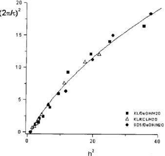
Figure 3. Measured points of (2d=)
2 vs the reduced
mag-netic eldh=H=Hc. is the length of the walls periodicity
as observed in the microscope anddis the thickness of the
slab.
When the scaling laws, Eq. (5), were applied to ex-perimental data of dierent samples it was veried that, indeed, all measured points extended along the same universal line[22]. In Fig. 3 we show the measured points for some dierent experimental data. It was used rationalized units for the magnetic eld in order to ob-tain the same scale. Observe that the points are spread and there is not any evident correlation among them. But, when the relations given in Eq. (5) are used the result shown in Fig. 4 is found. The continuous line is to be considered only as an eye's guiding.
expected to nd in the walls geometry some informa-tion about the physical condiinforma-tions prevailing in its ori-gin. Nevertheless, as it is observed in Fig. 4, the static parameters, through the appropriate scaling presented above, are enough to put the experimental data along a single curve. The success of the scaling laws in reduc-ing these experimental data to a universal line seems to indicate that there is also some unknown universality in the dynamical motion that built the walls. Below, a sketch of this demonstration will be given (see ref.[11] for details).
Figure 4. The points of Fig. 3 scaled in such a way that all of them stay along the same line. As demonstrated in the text, contrarily to the expected, the parameters of the scaling only depend on the elastic constants.
In order to accomplish this task, we look for some parameters characterizing the NLC media and use them
in Eq. (6). These NLC compounds, their viscosities coecients, and the references from where they were obtained are displayed in Table 1.
To each of these compounds the values of ~k2as
func-tion ofthat makes Eq. (14) maximum have been nu-merically found. These are the preferred ~k2. A
remark-able aspect of this result, shown in Fig. 5, is that for samples as distinct as the ones shown in the Table 1 the curves of the preferred ~k2 as a function of are
not so dierent. Only the elastic constant have been scaled and the viscosity coecients, that are explicitly present in Eq. (14) seemto play a not important role in this picture. Therefore, it remains to explain why the viscosity coecients become absent in the preferred ~k2
curve.
Figure 5. ~k 2 = (2
=)
2 vs the walls amplitude. To obtain
this picture only the elastic coecients have been scaled. The viscosity coecients are the ones reported in the NLC literature. Notice that the selected wave length is eectively independent of these coecients. The reduced magnetic eld was xed ath
2= 5.
Temp. (C) 1 2 3 12 1 K33=K22 References
MBBA 25 103 23.2 39.6 6 74.6 2.5 [23, 24] CBOOA 100 21.2 5.81 8 10.9 15.41 3.7 [25, 26]
HBAB 80 43.3 9.4 14.6 6 32.5 3(?) [23]
PAA 122 9.3 2.3 3.4 4 6.6 3.1 [20, 24]
MIXTURE 80 65.1 13.4 22 5 48.5 3(?) [23] 5CB 3(?) 86 17.6 33 ? 63.6 2.3 [27, 28]
Table 1: Viscosities in 10,3kgm,1s, the ratioK
33=K22;and the references from where these data were
obtained for several NLC compounds. The symbol \?" means that the corresponding value is unknown by the authors. The values of the K33=K22accompanied by (?) are attributed. The compound named
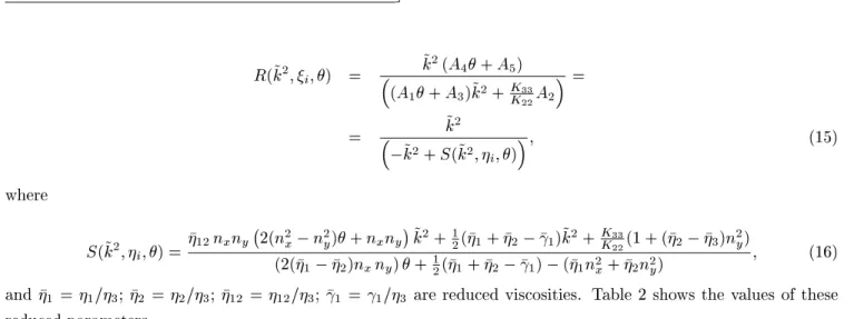
First of all, observe that the viscosity coecients appear, in Eq. (14), in the factor R(~k2;
i;;) which,
with some labour can be rewritten as
c
R(~k2;
i;) =
~
k2(A
4+A5)
(A1+A3)~k 2+
K33
K22A 2
=
= ~k2
,~k
2+S(~k2; i;)
; (15)
where
S(~k2;
i;) =
12nxny ,
2(n2 x
,n 2
y)+n xny
~
k2+ 1
2( 1+ 2
, 1)~k
2+ K33
K
22(1 + ( 2
, 3)n
2
y)
(2(1 ,
2)nxny)+ 1
2( 1+ 2
, 1)
,( 1n
2
x+ 2n
2
y)
; (16) and 1 =1=3; 2 =2=3; 12 =12=3; 1 =1=3 are reduced viscosities. Table 2 shows the values of these
reduced parameters.
1 2 12 1
1+2,1
2,1,1
1
2,1,1
MBBA 2.60 0.58 0.15 1.88 -0.33 -0.51 CBOOA 2.65 0.72 1.36 1.92 -0.38 -0.52 HBAB 2.96 0.64 0.41 2.23 -0.30 -0.44
PAA 2.73 0.67 1.18 1.94 -0.36 -0.50
MIXTURE 2.95 0.61 0.23 2.20 -0.30 -0.44
5CB 2.60 0.53 ? 1.92 -0.30 -0.50
Table 2: Reduced values of the viscosities i = i=3(i = 1;2;3); 12 = 12=3; and 1 = 1=3; for
several NLC compounds. The symbol \?" means that the value is unknown.
d
The reason for the coincidence of the preferred k2
curves become clear in Eqs. (15), (16), and Table 2. It is not the absolute values of these viscosity coecients that are important, but the relative ones. When com-pared with the dispersion of the Table 1, the relative values of the Table 2 are much more coincident. For example, in Table 1 the values for 1 range from 9:3
to 103 10,3kgm,1s: Meanwhile, in Table 2
1 ranges
from 2:60 to 2:96. The small variation of the relative values of the viscosity coecients is the responsible for the corresponding states of the NLC walls.
It is important to emphasize that although the rel-ative values of the viscosity coecients are much more coincident than the absolute ones, they are not exactly the same (see table 2). Therefore, one can expect to nd the presence of the viscosity coecients in the macro-scopic walls parameters through a little eect.
How-ever, the present data for the walls periodicityare not sucient to reveal it and we can arm that, if observed, such eect will be very small. It should be noticed that even being not determined at the moment at which the matter ow begins, the value ofmust be xed when the bending of the director is small. When this condi-tion is placed in Eq. (16) the parameters determining the preferred k2 curve are given by that presented in
the last two columns of Table 2.
vis-cosity coecients. They do not give any justication for the existence of this constant ratio. We believe that, as in the seminal work of Helfrich[29], it is related with the anisotropic shape of the nematic micelle.
IV The collapse of the magnetic
walls
As it is well known, for magnetic elds far above the Freedericksz threshold the walls tend to disappear[30, 31]. The basic mechanism for their destruction is the instability beginning at the moment in which the ux of matter[3] that gives rise to them stops. At this mo-ment the extremely harmonic and periodic walls pat-tern begins an unstable phase after which all its one-dimensional and periodic regularity is lost.
Habitually unstable congurations are found in physical systems after the action of some transient force operating during a nite time interval[32, 33]. While the transient action is working, the system goes to a conguration that, as soon as it vanishes, no longer has the least energy. In the walls case the transient force is given by the initial ux of the nematic material [3]. Of course, the fact that the walls do not have the least energy is a necessary, but not sucient, condition to promote their instability. In fact, the uid ow leads the system to a conguration that is an extremum of the energy but, as a simple elastic argument shows, it is not the conguration with the least energy[34]. But even not being in the ground state, the walls could be in a local minimum at which the system might remain indenitely. We have shown that, as the experiments conrm, the walls conguration is indeed a local free en-ergy maximum. In order to prove it, the second func-tional derivative of the free energy, around the walls conguration, was studied and it was shown that it is negative[13]. Nothing more than the oscillatory and one-dimensional character of the walls were assumed along that demonstration.
In order to fully appreciate the details of the walls wasting process, a wall prole, in which their geomet-rical parameters were shown, was constructed and ex-hibited in Fig. 6. This prole is described by three pa-rameters: the walls amplitude '
o, the walls length ,
and the walls form factor. The parameter;changing
between 0 and 1; controls the form of the wall. The
wall has two distinct regions[8]. In one of them (thew
region) the director bends its orientation from one con-guration to the symmetric one. The other region (the
region) describes a saturated portion of the director. The value gives the fraction of each portion. When !1;the wall becomes a single sine function. On the
other hand, when !0 the saturated region assumes
the entire wall. One observes from Fig. 6 that ;given
by
=,w=(1,); (17)
is a measure of the saturated portion of the wall. Fur-thermore, Eq. (14) has a conserved quantity [8,22,35]
C= 12(@ x
) 2
,
1 2
2+ 2 h
2
u(); (18)
which reects the homogeneity of the system along the
~ e
x direction.
C is a xed number that exists only as
long as the system remains one-dimensional. Therefore, its value at the point where= 0 can be compared with
its value at the region where@ x
= 0;giving
1 2'
2
o( 2
,) 2=
,
1 2'
2
o+ 2 h
2
u(' o)
; (19)
which shows that as long as the system in one-dimensional the parameters ; ; and '
o are not
in-dependent.
Figure 6. Graphic representation of a typical wall. It is explicitly shown the saturated portion =2, the bending
portion=2, and the amplitude'
o. The irreversible
expo-nential growing uctuations act in such a way to reduce the amplitude'
oand the saturated portion [13].
The collapse of the walls is dominated by the ran-dom uctuations around it. The uctuations com-manding this unstable process are the ones with grasps the least energy. This principle will lead to an inde-pendent development of , , and '
o and it is easy,
for example, to obtain the force between two neighbor walls[13] and to show that it is repulsive and decays with the inverse of the square of the wall's portion,
w = ,, where there is the director bending (see
Figs. 2 and 6). That is, shorter is the bend portion, more repulsive is the force between the wall. Finally, the minimization of the uctuations' energy led us to a similar conclusion for the wall's saturated portion and amplitude '
o: they become shorter and shorter
with time.
Since the sample is composed by a large number of walls, the repulsive force between them may be coun-terbalanced and the net result may be an equilibrium situation. However, there is no way to get a counter-balanced eect in the reduction of the walls saturated portion or in the reduction of the walls amplitude
'
o. Therefore the reduction in and '
o starts the
destruction of the walls.
V Concluding remarks
In conclusion, let us stress some important points aris-ing in our analysis of the physical properties of the walls. First of all we have shown that the family of pe-riodic walls appearing above the Freedericksz threshold can be reduced to a single physical situation through a law of corresponding states. This law is obtained by means of an appropriate choice of scale regarding the elastic constants and the critical eld.
In a second moment we demonstrate that the phys-ical reason for law of corresponding states lies in the behavior of the Miesowicz's viscosity coecients. In fact, we observe that the key to understand this law in the nematic medium is the existence of an approximate constant ratio between the viscosity coecients.
Finally, we would like to point out that our expla-nation for the collapse of the walls only takes care of the beginning of this process. It is experimentally ob-served that the walls evolve to closed structures having elliptical shape. Furthermore, it has to be stressed that even these closed elliptical walls are not stable.
Fre-quently they disappear of the NLC sample. In fact, the minimization of the energy of the uctuations leads to the destruction of the walls regular pattern by means of three mechanisms: a) a repulsive interaction; b) the re-duction of the walls saturated portion; c) the rere-duction of the walls' amplitude. We believe that we have pre-sented an important step towards a better understand-ing of these rich and complex non-linear phenomena in the NLC physics.
Acknowledgments
Financial support from the Conselho Nacional de Desenvolvimento Cientco e Tecnologico (CNPq) is ac-knowledged.
References
[1] P. G. de Gennes, The Physics of Liquid Crystals, (Clarendon Press, Oxford, 2nd edition, 1993).
[2] E. Guyon, R. Meyer and J. Salan, Mol. Cryst. Liq. Cryst.54, 261 (1979).
[3] F. Lonberg, S. Fraden, A. J. Hurd and R. B. Meyer, Phys. Rev. Lett.52, 1903 (1984).
[4] M. Sim~oes, Phys. Rev. E56, 3061 (1997).
[5] T. Kroin and A. M. Figueiredo Neto, Phys. Rev. A36,
2987 (1987).
[6] T. Kroin, A. J. Palangana and A. M. Figueiredo Neto, Phys. Rev. A39, 5373 (1989).
[7] A. J. Palangana, L. R. Evangelista and A. K. Zvezdin, Phys. Lett. A200, 56 (1995).
[8] M. Sim~oes, A. J. Palangana and L. R. Evangelista. Phys. Rev. E54, 3765 (1996).
[9] P. A. Santoro, A. J. Palangana, M. Sim~oes, Phys. Lett. A243, 71 (1998).
[10] H. E. Stanley, Introduction to Phase Transitions and Critical Phenomena, (Claredon Press, Oxford, 1971). [11] M. Sim~oes, A. A. Arroteia, Phys. Rev. E (1998) ( in
press)
[12] H. Kneppe, F. Scheneider, N. K. Sharma, Ber. Bun-senges Phys. Chem. 85,784 (1981).
[13] M. Sim~oes, A. J. Palangana, F. C. Cardoso, Phys. Rev. E58, 2011 (1998).
[14] J. L. Ericksen, Arch. Ratl. Mech. Anal.4, 231 (1960); 9, 371 (1962).
[15] F. M. Leslie, Quart. J. Mech. Appl. Math. 19 357
(1966).
[16] O. Parodi, J. Physique (Paris)31, 581 (1970).
[17] W. C. Oseen, Trans. Faraday Soc.29, 883 (1933).
[19] L.D. Landau, E. M. Lifshitz. Fluid Mechanics, (Butterworth-Heinemann, Oxford, 1995).
[20] W. H. de Jeu.Physical properties of liquid crystalline materials, (Gordon and Breach, New York, 1979). [21] G. Vertogen, W. H. de Jeu.Thermotropic Liquid
Crys-tals, Fundamentals, (Springer-Verlag, Berlin, 1988). [22] A.J. Palangana, M. Sim~oes, L. R. Evangelista, A. A.
Arroteia. Phys. Rev. E.56, 4282 (1997).
[23] C. H. Gahwiller, Mol. Cryst. Liq. Cryst. 20, 301
(1972).
[24] W. H. de Jeu, W. A. P. Claassen, A. M. J. Spruijt, Mol. Cryst. Liq. Cryst.37, 269 (1976).
[25] M. G. Kim, S. Park, Sr. M. Cooper, S.V. Letcher, Mol. Cryst. Liq. Cryst.36, 143 (1976).
[26] N. V. Madhusudana, P. P. Karat, S. Chandrasekhar, Pramona Suppl.1, 225 (1975).
[27] G. P. Chen, H. Takezoe, A. Fukuda. Liquid Crystal,5,
347 (1989).
[28] Chmielewski, Mol. Cryst. Liq. Cryst. 132339 (1986).
[29] W. Helfrich, J. Chem. Phys.52, 100 (1969);53, 2267
(1970);56, 3187 (1972).
[30] F. Brochard , J. Phys. (Paris)33, 607 (1972).
[31] L. Leger , Mol. Cryst. Liq. Cryst.24, 33 (1973).
[32] R. Kubo, M. Toda, N. Hashitsume.Statistical Physics II, Nonequilibrium Statistical Mechanics, (Springer-Verlag, Berlin, 1991).
[33] D. Chandler. Introduction to Modern Statistical Me-chanics, (Oxford University Press, New York, 1987). [34] E. A. Oliveira, G. Barbero and A. M. Figueiredo Neto,
Phys. Rev. E54, 5830 (1996).