Article
Printed in Brazil - ©2014 Sociedade Brasileira de Química0103 - 5053 $6.00+0.00
A
*e-mail: [email protected]
Melt sonoquenching: an Affective Process to Obtain New Hybrid Material and
Achieve Enhanced Electrochromic Performances Based on V
2O
5/2,4,5-tris(1-methyl-4-pyridinium)-imidazolide Tetrafluoroborate Nanofibers
Renato S. de Oliveira, Juliana da S. Goulart, Fabio S. Miranda and Eduardo A. Ponzio*
Instituto de Química, Universidade Federal Fluminense, Outeiro de São João Batista S/No., 24020-141 Niterói-RJ, Brazil
Materiais eletrocrômicos híbridos são uma classe de compostos muito importantes para o desenvolvimento de novas tecnologias baseadas em propriedades ópticas e eletroquímicas. Neste trabalho é relatada a síntese do novo híbridoV2O5.1,26H2O([C3N2(C6H7N)3])0,07 que utiliza a combinação de dois métodos tradicionais, o melting quenching e o sonoquímico. O material
resultante foi caracterizado por diversos métodos a fim de verificar as características físicas e químicas e a sua possível utilização como eletrodo eletrocrômico. O hóspede orgânico provoca uma diminuição do espaço entre as lamelas da matriz inorgânica e a interação eletrostática entre os grupos oxo da matriz do V2O5 com os anéis piridínios do hóspede orgânico demonstram uma forte interação. A nanoestrutura híbrida apresentou boa reversibilidade e ciclabilidade durante 50 ciclos, eficiência eletrocrômica de 22 cm2 C–1 (410 nm) e 96% de retenção de coloração após os 50 ciclos de mudança de cor.
Hybrid electrochromic materials are a very important class of compounds, because they enable new and/or better optical and electrochemical properties to be unfolded. This paper reports the synthesis of the new V2O5.1.26H2O([C3N2(C6H7N)3])0.07 using the combination of two traditional methods, melting quenching and sonochemistry. The new material was characterized by several methods in order to verify the physical and chemical characteristics and its possible use as an electrochromic electrode. The organic guest provokes an interlayer spacing decrease of the inorganic matrix and the electrostatic interaction between the oxo groups of the V2O5 matrix and the pyridinium rings of the organic guest demonstrate a strong interaction. The new hybrid nanostructure presented good reversibility and cyclability during 50 cycles, electrochromic efficiency of 22 cm2 C–1 (410 nm) and 96 % color retention after 50 cycles of color changing.
Keywords: electrochromic, hybrid materials, V2O5, nanofibers, melt sonoquenching
Introduction
Hybrid organic-inorganic materials have been used to develop new technologies based on the combination of organic and inorganic building blocks to generate multifunctional materials. A common method of preparation of organic-inorganic hybrid materials is the intercalation of organic molecules into layered inorganic compounds as
transition metals oxides.1
The hybrid materials take advantage of the best properties of each component and have found applications
in many fields such as optics, electronics, and others.2-5
Different transition metal oxides are used as hybrid
matrixes, for example: TiO2,6-11 Fe2O3,12,13 MnO2,14-16
WO3,17-21 V
2O5,2,22-24 and others.
Vanadium pentoxide (V2O5) xerogel has a versatile
lamellar structure that can intercalate a wide variety of
inorganic and organic guest species.25,26 Much effort has
been made to produce new types of hybrid vanadium oxide/ organic due to their potential applications in different fields such as: secondary batteries, catalysis, supercapacitor,
thermochromism and electrochromism.27,28
differences were reported on the potential and optical transmittance on thin films electrodes of amorphous and
crystalline vanadium oxide.27,29
V2O5 xerogels have lamellar (or 2D) structure suitable
for intercalation reactions. For this reason, V2O5 xerogel has
been regarded as a suitable host unit for organic-inorganic hybrid materials.
The strength of the intermolecular interactions between the organic guest and the inorganic matrix is responsible for the stability of the hybrid. Many studies have been
performed to improve the properties of the polyaniline/V2O5
system.23,30-32 The polymeric component stabilizes the hybrid
material probable due to a homogeneous distribution of the
induced stress during cycling. Oliveira et al.33synthesized
melanin/V2O5•nH2O and polyaniline/V2O5•nH2O hybrids.
They demonstrated that the presence of either melanin or polyaniline between the vanadium oxide layers causes an increase in the interplanar distances. Additionally, they provided an increase of electronic and ionic conductivity,
and improvements on the optical properties of the V2O5.
Several articles, dealing with the preparation of
devices and multifunctional materials using V2O5 have
been published.23,26,34-54 All the studies indicated that the
performance of the hybrid is affected by the synthetic route.
The vanadium oxide hybrids can be prepared by various techniques, among them we can highlight the sol-gel method, hydrothermal synthesis, (or mixed method sol-gel/ hydrothermal), sonochemistry, electrochemisty, chemical
polymerization, melting quenching, among others.23,26,34-49
The melting quenching presents some advantages as easy implementation and use of simpler and cheaper equipment, compared to sol-gel methodor mixed method sol-gel/hydrothermal, electrochemistry, and others. Melting intercalation is commonly used for production of composites and nanocomposites, particularly with
polymers55-57 but is little used for the synthesis of the
inorganic matrix for inorganic/organic hybrids. The use of vanadium oxide in the production of electrochromic hybrids is of great importance due to the possibility of creating new optical and electrochemical properties, thus making of these hybrids an important source for the production of multicolored materials, with better response times, electrochromic and coulombic efficiencies, and greater transmittance variations when applying different electric potentials.
In this paper, we present a fast and easy route to produce
a new nanostructured hybrid V2O5
/2,4,5-tris(1-methyl-4-pyridinium)-imidazolide nanofibers by a mixed method melt-quenching/sonochemistry (melt sonoquenching). The organic component is an unpublished molecule. This
novel hybrid has some special advantages: low-cost, good electrochromic response and the mixed method procedure is easily applicable for industrial purposes.
Experimental
Synthesis of 2,4,5-tr is (1-methyl-4-pyr idinium)-imidazolidetetrafluoroborate (TPI-Me(BF4)2)
All the reagents and solvents for synthesis and analysis were of analytical and/or spectroscopic grade and used without further purification. The 2,4,5-tris(4-pyridinyl)
imidazole (Htpim) was prepared as described elsewhere.58,59
A mixture of 200 mg (0.668 mmol) of Htpim and 0.5 mL (8.02 mmol) of methyl iodide in 9 mL of dimethylformamide (DMF) was heated at 100 °C with stirring for 15 h. After cooling to room temperature, ethyl acetate was added to the reaction mixture, the solid formed was filtered, washed with hexane resulting in an orange solid (293.8 mg, 78%). 200 mg (0.335 mmol) of 2,4,5-tris (1-methyl-4-pyridinium)-imidazolate iodide was
dissolved in water and 130 mg (0.668 mmol) of AgBF4
was added with stirring for 15 min. The AgI formed was filtered off and washed with distilled water. The filtrate was evaporated and the solid obtained was washed with ethyl ether resulting in a yellow solid (125.8 mg, 73%).
¹H NMR (DMSO-d6, 500 MHz) δ: 9.00 (d, 2H, J3 6.7 Hz),
8.90 (d, 4H, J3 6.6 Hz), 8.58 (d, 2H, J3 6.9 Hz), 8.25
(d, 4H J3 6.9 Hz), 4.35 (s, 6H), 4.34 (s, 3H). 13C NMR
(DMSO-d6,75 MHz,): 146.0, 145.7, 143.3, 136.4, 125.3,
122.5, 54.6, 54.5, 47.5, 47.4.
Instrumentation
1H and 13C NMR spectra were collected on a Varian
AS400 spectrometer. Elemental analyses were carried out on a CHN Varian EA 1100.
Synthesis of the V2O5.nH2O and hybrid material
Vanadium pentoxide xerogel (V2O5.nH2O) and hybrid
material were synthesized through melt quenching assisted with ultrasound (melt sonoquenching) using ammonium
metavanadate (NH4VO3) as precursor. In a porcelain
crucible 2.0 g de NH4VO3 was added, and heated at
800 °C during 1 h. After this step, the liquid formed was immediately spilled into 20.0 mL in a saturated aqueous
TPI-Me(BF4)2 at room temperature under the influence
of an ultrasound probe (Sonics Vibra-cell 130 W and 20 kHz-Probe No.630-0435) during 1 h. The procedure of
is with the aid of a claw 50 cm and using all necessary personal protective equipment. The hybrid material was left ageing for 7 days without stir and, at the end of this time, the gel produced was centrifuged and washed several times with ethanol and then dried at 110 °C for 24 h.
The material was deposited in indium tin oxide (ITO) substrate using spin-coating technique. The spin-coater used is homemade equipment; all parameter (rpm, time, concentration of suspension and volume apply) was the same for all materials studies for maintain the same geometric area, uniformity surface and film thickness. For all the depositions, it was used 1000 rpm, 1 min and
10 drops of a suspension of the materials (50 mg mL–1 in
acetonitrile). The exposed area was 0.84 cm2. The resulting
electrodes were allowed to 110 °C for 24 h.
Materials and methods
The crystalline structure of the powders was analyzed by X-ray powder diffraction (XRD). The diffractometer
used was a Bruker AXS D8 Advance (Cu Kα radiation,
40 kV and 40 mA) with LynxEye detector. The diffraction patterns were collected in a flat geometry with steps of 0.02° and accumulation time of 0.5 s per step.
Fourier transform infrared spectroscopy (FT-IR) measurements were taken in a Varian 660-FTIR spectrometer.
Thermal analyses were performed in a Shimadzu
TGA-60, using a heating rate of 5 °C min–1 from room
temperature to 600 °C in N2 with a flow rate of 50 mL min–1.
Surface morphology was investigated using a Jeol JSM-6701F scanning electron microscope (SEM). The accelerating voltage was preset at 5 kV. Imaging was obtained by a backscattering electron detector with the preset charge-up reduction mode. Jeol software was used to control the instrument.
Atomic force microscopy (AFM) were taken in a Nanosurf Flex AFM. The hybrid material was deposited on a Si substrate and images were acquired in tapping mode under ambient conditions, using the Nanosurf easyScan 2 Flex AFM scanner and cantilever type PPP-NCLR (Nanosensors).
A potentiostat/galvanostat Microautolab Type III and a spectrophotometer Ocean Optics USB650UV were used for the spectroelectrochemical measurements. The electrochemical cell was composed of a quartz cuvette with 1 cm optical path containing three electrodes. The working electrode was glass covered with ITO with the composite deposited on a conducting surface using the technique of spin-coating, the counter electrode was a Pt wire and the quasi-reference electrode was a silver wire coated with
AgCl. A solution of 0.5 mol L–1 LiClO
4 in acetonitrile
was used as electrolyte. The optical and electrochemical measurements were carried out at room temperature.
Results and Discussion
Synthesis and characterization of TPI-Me(BF4)2
The synthesis of TPI-Me(BF4)2 is straight forward,
the Scheme 1 shows the synthetic route. Htpim was
prepared as described by Proskurnina et al.58,59 followed
by the alkylation60 of the pyridines resulting in the TPI-Me
diiodide with yield of 78% (see Scheme 1). The exchange of the anion by by salt metathesis reaction can be verified
by the infrared spectrum, which has the characteristic BF4–
band at 1050 cm–1. The deprotonating of the imidazole is
due to the weakness of the N–H bond caused by the strong electron-withdrawing effect of the three cationic pyridyl groups connected to each carbon of the imidazole ring. In this case, the water molecules from the metathesis solution keep the media alkaline enough to remove the imidazole proton. The synthesized compounds were analyzed by
1H NMR spectroscopy and 13C (Supporting Information).
Hybrid material
The melt sonoquenching synthesis used in the production of vanadium oxide is based on heating the vanadium oxide at temperatures above its melting point with subsequent abrupt cooling to room temperature. The
heating at 800 °C of the NH4VO3 for 1 h was enough for
the precursor total decomposition, forming the vanadium pentoxide, according to reaction 1. The melting point of the
vanadium oxide occurs at a temperature of 670 °C, forming vanadium oxide in liquid state, according to reaction 2. When turning the liquid vanadium oxide into saturated
solution of TPI-Me(BF4)2 under ultrasonic processors at
room temperature, a gel is immediately formed with a orange color, according to reaction 3. The
green-orange color is because the incorporation of TPI-Me2+ that
induces the reduction of part of V+5 to V+4.
(1)
(2)
(3)
The influence of ultrasonic irradiation on heterogeneous media is complex since it may involve several physical and chemical processes, such as the production of microstreaming, microstreamers, microjets, shock waves reactive free radicals, mass transfer, enormous local temperatures and pressures, mixing, solid erosion, all
associated with the process of cavitation.61-66
Currently, the influence of TPI-Me2+ and the mechanism
of formation of the hybrid nanofibers are still under investigation. Apparently, the use of the ultrasonic bath in the cooling process impairs crystal growth, since the uniform and fast cooling creates a kinetic condition unfavorable to the occurrence of recrystallizations during cooling. The reactions induced by low frequency ultrasound, more violent cavitation, resulting in higher localized temperatures and pressure improve the intercalation of the organic compound.
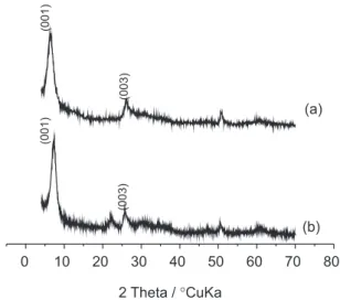
XRD measurements of the matrix intercalation
(V2O5•nH2O xerogel) and the hybrid material were
performed, and are shown in Figure 1. The XRD pattern
of the matrix indicates the presence of the peak at 2θ =
6.2º for the (001) diffraction plane, as expected for a layered material with the layers parallel to the reflection plane, corresponding to the interlayer distance of 14.2 Å,
which is consistent with data found in the literature.67-69 It
is possible to observe a second peak at 2θ = 26° for the
(003) diffraction plane, according to the literature.26,33,70,71
It is important to note also that the X-ray diffraction pattern is characteristic of an amorphous material. Diffraction pattern of the hybrid material, Figure 1b,
shows the same peak of matrix at 2θ = 26°, but it shows a
diffraction peak at 2θ = 7.2º for the (001) diffraction plane,
corresponding to the interlayer distance of 12.2 Å. The interlayer spacing decreases from 14.2 Å to 12.2 Å. This might correspond to water expulsion and to the
thickness of TPI-Me2+ molecules lying flat between V
2O5
ribbons. As shown in Figure 1a and b, the relative intensities
of the (001) diffraction plane of V2O5 (I001/I110 = 3.0)
and hybrid (I001/I110 = 2.9) are similar. The hybrid presents
strong (001) reflexions as one would expect for a well-organized intercalation compound. The increase of the crystallinity of hybrid materials has also been observed
elsewhere.33,70 This is a clear indication that the 1D order
along the c* axis of the material is not lost. Nevertheless, our XRD data will obviously need confirmation by other techniques.
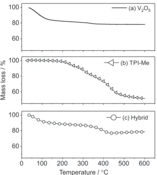
It is noteworthy that these interlamellar distances are relative, because they are directly dependent on the new composition of hybrid materials produced. So, in order to verify the composition and thermal stability, the hybrid material synthesized was characterized through thermogravimetric measures, according to Figure 2.
Figure 2a presents the thermogram of V2O5•nH2O
xerogel where two regions of weight loss can be observed. The first weight loss extends to 130 °C and is related to the loss of absorbed water interlayer of vanadium oxide. The second weight loss, of less intensity, occurs from 320 to 360 °C and is attributed to the release of water molecules coordinated to the vanadyl group and molecules present in
the plane of the lamella.71 The probable composition of the
intercalation matrix is V2O5.2.8H2O.
Figure 2b shows the thermogram of the intercalating
TPI-Me(BF4)2. It is possible to check a very intense
weight loss in three consecutive steps, starting at 180 °C and extending up to 600 °C, related to the decomposition
of the TPI-Me(BF4)2. In the thermogram of the hybrid,
Figure 2c, there is an initial weight loss extending up to 130 °C related to water loss and a second weight loss that occurs from 290 to 430 °C is due to the decomposition of
the TPI-Me(BF4)2 interlayer.
T h e c o m p o s i t i o n w a s d e t e r m i n e d t o b e
V2O5.1.26H2O([C3N2(C6H7N)3])0,07 based on the
consecutive weight loss of water and polymer, i.e., .
The FT-IR spectra of V2O5 xerogel, TPI-Me(BF4)2
and TPI-Me/V2O5 hybrid are shown in Figure 3. The
characteristic bands of V2O5 xerogel are clearly observed in
Figure 3a specifically, the three absorption bands centered
at 535, 798 and 995 cm–1 assigned to symmetric and
asymmetric stretching modes of V–O–V (νsy and νasy) and
symmetric stretching mode of the V=O (νs), respectively.72
The infrared spectrum of TPI-Me(BF4)2 (Figure 3b),
shows a band at 854 cm–1 assigned to the C–H
out-of-plane bending vibration of pyridinium rings. The doublet
at ca.1039-1059 cm–1 confirms the ion in the structure.73
The bands at 1365 and 1435 cm–1 are attributed to ν(C=N),
1635 and 1737 cm–1 to ν(C–C
aromatic), 2970 cm–1 ν(C–Haliphatic)
and 3025 cm–1 ν(C–H
aromatic).
For the TPI-Me/V2O5 hybrid (Figure 3c), the intercalation
of TPI-Me2+ is evidenced by the presence of the TPI-Me2+
peaks between 1000-3200 cm–1. The V–O–V vibration
at 798 cm–1 (V
2O5) shifted to 748 cm–1 (TPI-Me/V2O5),
indicating a strong electrostatic interaction between V2O5
and TPI-Me2+. The vanadyl V=O vibration band at 995 cm–1
in the V2O5 xerogel shifted to 985 cm–1 upon intercalation of
TPI-Me2+ into V
2O5. This shift suggests a strong interaction
between vanadyl group and the incorporated TPI-Me2+. The
characteristic absorption band of the ion disappeared in
the hybrid suggesting that the intercalated TPI-Me2+ in the
oxide matrix is stabilized by the anionic nature of the V2O5.
This is confirmed by the shift of the ν(C=N) bands to lower
wavenumbers in the TPI-Me/V2O5 hybrid, that confirm the
electrostatic interaction between the oxo groups from the
V2O5 matrix and the pyridinium rings of the organic guest.
All these interactions between V2O5 and TPI-Me confirm
the interlayer spacing decrease as shown in the XRD results.
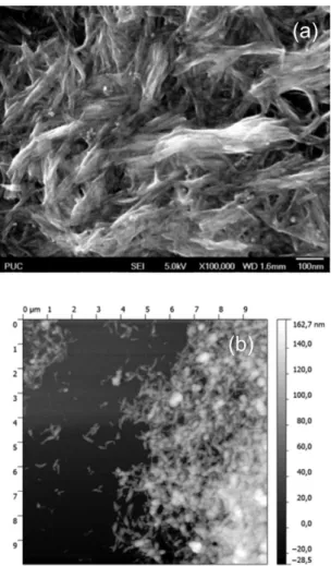
The hybrid was characterized by SEM and AFM, as shown in Figure 4a and b respectively. There is an aggregate fibrous morphology. In Figure 4b, a fiber medium length of 300 nm and medium width of 30 nm. The film thickness is determined by AFM ca.112 nm. It is also found that these submicrosized particles are aggregates made of much smaller nanofibers.
In order to understand the effect of the incorporation
into V2O5 in the electrochemical performance
electrochemical experiments as cyclic voltammetry (CV)
and chronoamperometry method with UV-Vis in situ were
carried out.
The CV experiment (Figure 5), under conditions of continuous potentiodynamic cycling at a scan rate
of 10 mV s–1, started from open circuit potential
(0.38 V vs. Ag), scanning in the positive direction until
1.2 V and then, scanning in the negative direction until
–0.6 V. The CV is very similar to that of V2O5 xerogel,
with two well-defined anodic peaks at 0.14 V and at
0.56 V (vs. Ag), these waves are ascribed to the V4+ to V5+,
presumably due to the Li+ deinsertion in two non-equivalent
sites in the vanadium oxide matrix. This first cycle confirms that the green-orange color is caused by the incorporation
of TPI-Me2+ which induces the reduction V+5/V+4. In the
reduction process, broad peaks localized at 0.27 V and at –0.49 V are observed and correspond to the intercalation of
Li+. After 10 cycles, a little decrease of anodic and catodic
current is observed, which corresponds to the organization
Figure 2. Thermal analyses measurements for V2O5.nH2O in (a), TPI-Me(BF4)2 in (b) and hybrid in (c).
Figure 3. FT-IR spectra for intercalation matrix in (a), for intercalated in
of layers of V2O5 when Li+ is intercalated. The TPI-Me2+ is
electrochemically active (support information), but in the hybrid, the organic part apparently does not contribute to the overall redox process in the potential range used.
It must be noticed that, as a consequence of the synergistic effect between the two components, the
hybrid with fiber shape is electroactive in this range of potential.
The color transitions have been further investigated by recording the film absorption spectra at controlled potential. The vanadium oxide xerogel in a yellow-colored state may be converted to a green and/or blue-colored state upon inserting and extracting ions and electrons. It is observed an absorption band at 410 nm that is related to the transfer process the ligand-to-metal charge transfer
(LMCT) transition of O2– to V5+ and d-d transition of V4+
in the range of 530-850 nm, which is consistent with data
from Gao et al.74 and Liu et al.75
Figure 6 shows the inspected UV-Vis spectra when applying a series of potential differences using chronoamperometry considering every spectrum was inspected when the current found its stability. UV-Vis spectroscopy was used to investigate the oxidation state changes of the hybrid. At –0.6 V (coloration state) it presents two absorption peaks, one with large absorption at 338 nm and another large peak at ca. 700 nm. The region 400-1000 nm corresponds to the d-d transition that occurs
for V (+4) in the V2O5 matrix and the strong peak at 340 nm
is assigned to the π-π* transition of the piridinium ring.
When more positive potential is applied the peak of
the π-π* transition of the piridinium ring is shifted by
18 nm to a longer wavelength (358 nm). When applied potential, imposing 1.2 V (bleaching state), two bands are
observed, at 348 nm (π-π* transition of the piridinium ring)
and at 410 nm assigned to transference for the V (+5) in
the inorganic matrix; according to Ryczkowsky76 the load
transference of the binder to the metal (LMTC).
Figure 7 shows the variation of potential, absorbance and intensity in a 3D graph. Over the region from 540
to 850 nm, the absorption of the d-d transition of V2O5
Figure 4.SEM image in (a) and AFM image in (b).
Figure 5. Cyclic voltammograms of hybrid material.
decreases from 0.60 to around zero with potential increase; the absorption intensity increases from 1.00 to 1.70 for the
LMCT transition and the π-π* transition of the organic
compound shows an increase, from 1.00 (–0.6V) to 2.00 (0.2 V) and a decrease from 2.00 (0.2 V) to 1.78 (1.2 V) followed by a wavelength shift from 340 (–0.6 V) to 358 (1.2 V) nm.
Vanadium oxide undergoes structural modification
during the Li+ insertion process induced by mechanical
stress leading.23 These structural modifications arise from
a variety of sources such as solvent transport into or out of the material during redox cycling, volumetric changes due to the electrochemical intercalation/deintercalation of
Li+ and changes in the coordination geometry at the metal
center that result from the redox transition. When lithium is deintercalated (1.2 V) results in increased interlamellar separation and leads to a decrease in steric and electrostatic effects promoted by the higher interlamellar distance; in this situation the organic compound improves the effective
degree of π-electron delocalization of the piridinium rings
and increases the intensity of the π-π* transition. On the
other hand, when Li+ is intercalated (–0.6 V) results in
decreased interlamellar separation and leads to a reduction of the partial charge of the N in the piridinium ring,
therefore reducing the intensity of the π-π* transition.
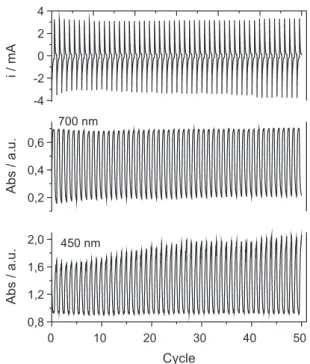
Other electrochromic parameters were studied, such as response time, efficiency and reversibility. Chronoamperometric analysis (Figure 8) was also carried
out, with follow-up of optical density variations in situ,
using a 450 and 700 nm wavelength, in which there was a successive application of –0.6 V for 60 s and 1.2 V for 60 s, and the evolution of color variation on the material could be observed as a result of the cycles. It was also noted that
the optical density (OD) variation in situ was 0.73 (450 nm)
in the first cycle and increased to 1.09 in the last cycle.
According to the analysis, after 50 cycles ∆OD increased
43.6%. At 700 nm the ∆OD showed a little reduction of 4%.
The electrochromic response time (t) is the time necessary for the material to change color, although there is no specific criterion to determine this response time, it can be obtained by the total transmittance variation (or
absorbance) or by a fraction of this.77 In this study, the
response time calculation was defined as the necessary time from the beginning of the pulse until it reaches 50% of the total transmittance or absorbance variation of each pulse. In analyzing the response times necessary for the oxidation and reduction of the material a significant difference between them can be noticed. The response time of the reduction (around 12 s) was always higher than the response time for the oxidation (less than 5 s)
throughout the 100 cycles, indicating that the V2O5 film
takes approximately 2.4 times longer to reach the reduced
state than to reach the oxidized state,78 reported the
color-switching time of vanadium oxide nanofibers to be 5 s and 6 s from the bleached state to the colored state and from the
colored state to the bleached state. Cao et al.79reported that
a 30% transmittance change at 700 nm took 50 s for a V2O5
nanorod, and 300 s was required for a sol-gel V2O5. For
electrochromic applications, immediate color-switching is very important. The rates of coloring and bleaching depend on the lithium ion diffusion and are related to the distance in the interlayer space of the nanofibers. In our case, the hybrid nanofibers are 30 nm wide, which provides a short
diffusion distance, but the TPI-Me2+ charge difficults the
diffusion of Li+ in the inorganic matrix, therefore the hybrid
presents a long response time.
The electrochromic and coulombic efficiencies were
calculated. The electrochromic efficiency was 22 cm2 C–1
(700 nm) and the coulombic efficiency for the first and fiftyth cycles were 0.94 and 0.97, respectively. At 450 nm
the electrochromic efficiency was 14 cm2 C–1 and the
coulombic efficiency the same as at 700 nm.
An essential characteristic that must be searched in these types of materials is their electrochromic stability, because they are subjected to multiple intercalation/
deintercalation of Li+. The hybrid nanofibers shown in this
work exhibited good long-term cycle stability; at 450 nm
the ∆OD increased from 0.72 to 1.12 and at 700 nm
there was less than 4% drop in coloration contrast after 50 switching cycles. These results demonstrate a substantial improvement in cycling efficiency of the hybrid, and that
the insertion of the TPI-Me2+ into the inorganic matrix
resulted in an assembled hybrid structure which led to the stabilization of the electrochromic response.
Conclusion
This contribution demonstrates that it is possible to obtain an inedited hybrid nanomaterial using the mixed technique, melting quenching and ultrasound. This hybrid, with defined morphology, can be used as electroactive material in electrochromic electrodes. In the proposed method of synthesis, it is possible to obtain a hybrid with 0.07 mol
of TPI-Me2+ per mol of V
2O5. The experimental tools used
allowed the characterization of the morphology and local
structure showing that the TPI-Me2+ causes an interlayer
spacing decrease of the inorganic matrix and the electrostatic
interaction between the oxo groups from the V2O5 matrix
and the pyridinium rings of organic guest demonstrates a strong interaction. These new hybrid nanostructures improve the electrochromic performance, as it was shown by using
spectroelectrochemical analysis. After 50 cycles the ∆OD
increased 43.6%. At 700 nm the ∆OD showed a little reduction
of 4%. The hybrid exhibited good long-term cycle stability,
at 450 nm the ∆OD increased 43.6% and at 700 nm with
less than 4% drop in coloration contrast after 50 switching
cycles, the electrochromic efficiencies were 22 cm2 C–1
(700 nm) and 14 cm2 C–1 (450 nm), and the coulombic
efficiency was 97%, indicating that this hybrid possesses great potential to be used in electrochromic electrodes.
Supplementary Information
Supplementary data are available free of charge at http://jbcs.sbq.org.br as PDF file.
Acknowledgments
The authors are grateful to the Coordenação de Aperfeiçoamento de Pessoal de Nível Superior (CAPES), Fundação Carlos Chagas de Amparo a Pesquisa do Estado do Rio de Janeiro (FAPERJ, E-26/102.971/2012 and E-26/111.407/2013), and Pró-reitoria de Pesquisa, Pós-graduação e Inovação (Proppi-UFF) for constant financial support and to Professor Jackson Antonio Lamounier Camargos Resende and LDRX-UFF for the XRD measurements.
References
1. Kang, S.-G.; Kim, K. M.; Park, N.-G.; Ryu, K. S.; Chang, S.-H.;
J. Power Sources2004, 133, 263.
2. Gomez-Romero, P.; Adv. Mater.2001, 13, 163.
3. Ferreira, M.; Zucolotto, V.; Constantino, C. J. L.; Temperini, M. L. A.; Torresi, R. M.; Oliveira Jr, O. N.; Synth. Met.2003,
137, 969.
4. Loy, D. A.; Shea, K. J.; Chem. Rev.1995, 95, 1431.
5. Sanchez, C.; Julian, B.; Belleville, P.; Popall, M.; J. Mater. Chem.2005, 15, 3559.
6. Schnitzler, D. C.; Zarbin, A. J. G.; J. Braz. Chem. Soc.2004,
15, 378.
7. Nogueira, A. F.; Micaroni, L.; Gazotti, W. A.; De Paoli, M.-A.;
Electrochem. Commun.1999, 1, 262.
8. Murakoshi, K.; Kogure, R.; Wada, Y.; Yanagida, S.; Chem. Lett.
1997, 26, 471.
9. Murakoshi, K.; Kogure, R.; Wada, Y.; Yanagida, S.; Sol. Energy Mater. Sol. Cells1998, 55, 113.
10. Wang, G.; Chen, H.; Zhang, H.; Yuan, C.; Lu, Z.; Wang, G.; Yang, W.; Appl. Surf. Sci.1998, 135, 97.
11. Kobayashi, N.; Teshima, K.; Hirohashi, R.; J. Mater. Chem.
1998, 8, 497.
12. Bidan, G.; Jarjayes, O.; Fruchart, J. M.; Hannecart, E.; Adv. Mater.1994, 6, 152.
13. Wan, M.; Zhou, W.; Li, J.; Synth. Met.1996, 78, 27.
14. Kuwabata, S.; Kisimoto, A.; Tanaka, T.; Yoneyama, H.;
J. Electrochem. Soc.1994, 141, 10.
15. Yoneyama, H.; Kishimoto, A.; Kuwabata, S.; J. Chem. Soc., Chem. Commun.1991, 986.
16. Gemeay, A. H.; Nishiyama, H.; Kuwabata, S.; Yoneyama, H.;
J. Electrochem. Soc.1995, 142, 4190.
17. Yoneyama, H.; Shoji, Y.; J. Electrochem. Soc.1990, 137, 3826. 18. Yoneyama, H.; Hirao, S.; Kuwabata, S.; J. Electrochem. Soc.
1992, 139, 3141.
19. Shen, P. K.; Huang, H. T.; Tseung, A. C. C.; J. Electrochem. Soc.1992, 139, 1840.
20. Jelle, B. P.; Hagen, G.; Noedland, S.; Electrochim. Acta1993,
21. Avvaru, N. R.; Rajeshwar, K.; Analyst.1998, 123, 113. 22. Shi, Z.; Zhang, L.; Zhu, G.; Yang, G.; Hua, J.; Ding, H.; Feng, S.;
Chem. Mater.1999, 11, 3565.
23. Ponzio, E. A.; Benedetti, T. M.; Torresi, R. M.; Electrochim. Acta2007, 52, 4419.
24. Hagrman, P. J.; Zubieta, J.; Inorg. Chem.2001, 40, 2800.
25. Wang, Y.; Cao, G.; Chem. Mater.2006, 18, 2787.
26. Zampronio, E. C.; Greggio, D. N.; Oliveira, H. P.; J. Non-Cryst. Solids2003, 332, 249.
27. Oliveira, M. R. S.; Mello, D. A. A.; Oliveira, R. S.; Ponzio, E. A.; Oliveira, S. C. In Advances in Nanotechnology; Bartul, Z.; Trenor, J., eds.; Nova Publishers: New York, 2011, Vol. 8, p. 1. 28. Bazito, F. F. C.; Fiorito, P. A.; Ponzio, E. A.; Vidotti, M.; Torresi, S. I. C.; Torresi, R. M. In Handbook of Organic Electronics and Photonics; Nalwa, H. S., ed.; American Scientific Publishers: California, 2008; Vol. 3, p. 51.
29. Scarminio, J.; Talledo, A.; Andersson, A. A.; Passerini, S.; Decker, F.; Electrochim. Acta1993, 38, 1637.
30. Leroux, F.; Koene, B. E.; Nazar, L. F.; J. Electrochem. Soc.
1996, 143, L181.
31. Kuwabata, S.; Idzu, T.; Martin, C. R.; Yoneyama, H.;
J. Electrochem. Soc.1998, 145, 2707.
32. Lira-Cantu, M.; Gomez-Romero, P.; J. Electrochem. Soc.1999,
146, 2029.
33. Oliveira, H. P.; Graeff, C. F. O.; Brunello, C. A.; Guerra, E. M.;
J. Non-Cryst. Solids2000, 273, 193.
34. Boyano, I.; Bengoechea, M.; de Meatza, I.; Miguel, O.; Cantero, I.; Ochoteco, E.; Rodriguez, J.; Lira-Cantu, M.; Gomez-Romero, P.; J. Power Sources2007, 166, 471. 35. Malta, M.; Louarn, G.; Errien, N.; Torresi, R. M.; J. Power
Sources2006, 156, 533.
36. Anaissi, F. J.; Engelmann, F. M.; Araki, K.; Toma, H. E.; Solid State Sci.2003, 5, 621.
37. Wang, G.; Zhao, J.; Li, X.; Li, C.; Yuan, W.; Synth. Met.2009,
159, 366.
38. Boyano, I.; Bengoechea, M.; de Meatza, I.; Miguel, O.; Cantero, I.; Ochoteco, E.; Grande, H.; Lira-Cantu, M.; Gomez-Romero, P.; J. Power Sources2007, 174, 1206.
39. Guerra, E. M.; Ciuffi, K. J.; Oliveira, H. P.; J. Solid State Chem.
2006, 179, 3814.
40. Kwon, C.-W.; Vadivel, M. A.; Campet, G.; Portier, J.; Kale, B. B.; Vijaymohanan, K.; Choy, J.-H.; Electrochem. Commun.
2002, 4, 384.
41. Wu, C.-G.; Chung, M.-H.; J. Solid State Chem.2004, 177, 2285.
42. Huguenin, F.; Ticianelli, E. A.; Torresi, R. M.; Electrochim. Acta2002, 47, 3179.
43. Ren, X.; Shi, C.; Zhang, P.; Jiang, Y.; Liu, J.; Zhang, Q.; Mater. Sci. Eng., B2012, 177, 929.
44. Huguenin, F.; Torresi, R. M.; J. Phys. Chem. C2008, 112, 2202. 45. Malta, M.; Torresi, R. M.; Electrochim. Acta2005, 50, 5009.
46. Huguenin, F.; Torresi, R. M.; Quim. Nova2004, 27, 393.
47. Soltane, L.; Sediri, F.; Ceram. Int.2013, 40, 1531.
48. Soltane, L.; Sediri, F.; Mater. Sci. Eng., B 2013, 178,
502.
49. Oliveira, R. S.; Alves, W. A.; Ponzio, E. A.; ECS Trans.2012,
43, 363.
50. Cao, Z.; Wei, B.; Nano Energy2013, 2, 481.
51. Mohd Yusoff, A. R. B.; Kim, H. P.; Jang, J.; Org. Electron.2013,
14, 858.
52. Wang, S.; Kang, Y.; Wang, L.; Zhang, H.; Wang, Y.; Wang, Y.;
Sens. Actuators, B2013, 182, 467.
53. Guo, H.; Liu, L.; Wei, Q.; Shu, H.; Yang, X.; Yang, Z.; Zhou, M.; Tan, J.; Yan, Z.; Wang, X.; Electrochim. Acta2013,
94, 113.
54. Wung, C. J.; Wijekoon, W. M. K. P.; Prasad, P. N.; Polymer
1993, 34, 1174.
55. Liu, X.; Wu, Q.; Polymer2001, 42, 10013.
56. Wang, S.; Long, C.; Wang, X.; Li, Q.; Qi, Z.; J. Appl. Polym. Sci.1998, 69, 1557.
57. Kumar, S.; Jog, J. P.; Natarajan, U.; J. Appl. Polym. Sci.2003,
89, 1186.
58. Lozinskaya, N. A.; Tsybezova, V. V.; Proskurnina, M. V.; Zefirov, N. S.; Russ. Chem. Bull.2003, 52, 674.
59. Proskurnina, M. V.; Lozinskaya, N. A.; Tkachenko, S. E.; Zefirov, N. S.; Russ. J. Org. Chem.2002, 38, 1149.
60. Alcalde, E.; Dinares, I.; Frigola, J.; Jaime, C.; Fayet, J. P.; Vertut, M. C.; Miravitlles, C.; Rius, J.; J. Org. Chem.1991, 56, 4223.
61. Chen, D. In Handbook on Applications of Ultrasound: Sonochemistry for Sustainability; Chen, D.; Sharma, S. K.;
Mudhoo, A., eds.; CRC Press: 2011, p 739.
62. Thompson, L. H.; Doraiswamy, L. K.; Ind. Eng. Chem. Res.
1999, 38, 1215.
63. Adewuyi, Y. G.; Ind. Eng. Chem. Res.2001, 40, 4681.
64. Gedanken, A.; Ultrason. Sonochem.2004, 11, 47.
65. Kuppa, R.; Moholkar, V. S.; Ultrason. Sonochem.2010, 17,
123.
66. Wu, T. Y.; Guo, N.; Teh, C. Y.; Hay, J. X. W.; Advances in Ultrasound Technology for Environmental Remediation, 1st ed;
Springer: Cham, CH, 2013.
67. Pyun, S.-I.; Bae, J.-S.; J. Power Sources1997, 68, 669. 68. Arashiro, E.; Zampronio, E. C.; Brunello, C. A.; Lassali, T. A. F.;
Oliveira, H. P.; Graeff, C. F. O.; Int. J. Inorg. Mater.2001, 3, 727. 69. Park, N.-G.; Ryu, K. S.; Park, Y. J.; Kang, M. G.; Kim, D.-K.;
Kang, S.-G.; Kim, K. M.; Chang, S.-H.; J. Power Sources2002,
103, 273.
70. Oliveira, H. P.; Graeff, C. F. O.; Zanta, C. L. P. S.; Galina, A. C.; Goncalves, P. J.; J. Mater. Chem.2000, 10, 371.
71. Oliveira, H. P.; Graeff, C. F. O.; Rosolen, J. M.; Mater. Res. Bul.1999, 34, 1891.
72. Leroux, F.; Goward, G.; Power, W. P.; Nazar, L. F.;
J. Electrochem. Soc.1997, 144, 3886.
74. Gao, X.; Banares, M. A.; Wachs, I. E.; J. Catal.1999, 188, 325. 75. Liu, J.; Zhao, Z.; Xu, C.; Duan, A.; Zhu, L.; Wang, X.; Catal.
Today2006, 118, 315.
76. Ryczkowski, J.; Catal. Today2001, 68, 263.
77. Chary, K. V. R.; Kumar, C. P.; Naresh, D.; Bhaskar, T.; Sakata, Y.; J. Mol. Catal. A: Chem.2006, 243, 149.
78. Cheng, K.-C.; Chen, F.-R.; Kai, J.-J.; Sol. Energy Mater. Sol.
Cells2006, 90, 1156.
79. Takahashi, K.; Wang, Y.; Cao, G.; Appl. Phys. Lett.2005, 86,
53102.
Submitted on: September 5, 2013