A New Double Probe System for Studies of Non-Uniform Plasmas
G. Petraconi and H. S. Maciel
Instituto Tecnol´ogico de Aeron´autica- ITA, Laborat´orio de Plasma e Processos- LPP
Prac¸a Marechal Eduardo Gomes, 50, 12228-900, S ˜ao Jos´e dos Campos, SP, Brazil
Received on 25 February, 2003. Revised version received on 22 May, 2003
A theoretical and experimental study was developed about the applicability of a double probe system consisting of two directional Langmuir probes, both probes being located separately in a plasma column. The current- volt-age characteristic of the double probe was obtained considering a plasma with a drifting maxwellian electron velocity distribution function and stationary ion background. In deriving the characteristic of the double probe, the plasma parameters, namely, electron temperature (Te), electron density (Ne), electron drift velocity (Vde) and plasma potential (Vp)are assumed to be non-uniform. The double probe characteristic is also dependent on the angle between the axial direction of the electron drift and the normal to the collecting area of the probe. Each probe can be rotated such that this angle can be varied between zero and 180 degrees. Various probe char-acteristics were simulated using plasma parameters obtained by independent single probe measurements in the positive column of a low-pressure arc discharge in mercury vapor. Typical parameters of the positive column, used in the simulation, are:Te= 5 eV,Ne= 10
17
m−3,v
de = 8x10
5
ms−1. Experimental characteristics of
the double probe were obtained and compared with the simulated results, showing good agreement. It is con-cluded that this directional probe system can be a reliable diagnostic tool especially for studies of non-uniform plasmas.
1
Introduction
Double probe method [1,2] is widely used for the study of plasmas properties. Most of the probe theories consider the case of a plasma at rest. However, in some plasmas [3,4] the electron drift velocity in the axial direction, which is prin-cipally responsible for carrying the discharge current, may reach an appreciable fraction of the thermal velocity, alter-ing the electron drift velocity distribution from maxwellian to Drift-maxwellian form. Under these circumstances, it is important to recognize the signature of the drifting electrons in the double probe characteristic. Ariga [5] has theoret-ically treated the characteristic of double probes immersed in plasma in which electrons and ions have a drift velocity in the axial direction, with the ion saturation current dependent on the ion temperature (Ti).
In this work, we consider the case of a plasma column of a low-pressure mercury arc dishcarge and we assume that the velocity distribution function of the electrons at the axis is maxwellian, with a superposed drift in the axial direc-tion. The ion current collected by the probe is given by the Bohm’s current [1]. Thus, the ion flux is assumed with-out drift and not affected by the probe potential. The basic equations for the electron and ion currents are shown in sec-tion 2, including the analysis of the floating potential and of the slope of the double probe characteristic near zero cur-rent. The effect of electron drift velocity on the double probe characteristic was simulated inserting the plasma parameters determined along the axis of the plasma column using single electrostatic probes. In section 3, we provide a concrete ex-ample of the application of this model by fitting data from a low-pressure mercury-arc discharge [3,4]. Agreement with the theoretical model is found quite good.
2
Directional double probe method
Directional double probe system is constituted by two plane Langmuir probes introduced into the plasma and connected to a dc symmetric supply unit so as to vary not only the volt-ageVa between the probes but its polarity as well. Fig. 1 shows the double probe measuring circuit and the potential distribution in a floating double probe system. In this figure,
Vais the differential voltage applied between the probes, is the potential difference between the regions of the plasma where the probes are located (Vp2− −Vp1),V1andV2are
the potential difference between the probe and the surround-ing plasma.
Each probe can be rotated such that the angle (θ) be-tween the axial direction of the electron drift and the normal to the collecting area of the probe can be varied between zero and 180 degrees. In this work, unlike the case of an ordinary double probe system, the distance (s) between the probes can be varied at large values. Vf1 andVf2 are the
floating potential of the probes 1 and 2 when the angleθof both probes is 00
(frontal electrodes). The floating double probe circuit having back to back electrodes is obtained by rotation of the probe 2 at the angleθof 1800
, in this case, the floating potential of the probe 2 isV′
f2.
2.1
Derivation of the double probe
character-istic equation
drifting electrons. Thez-axis is perpendicular to the probe surface and points to it. That is, electrons with a z
cathode
(ground) anode
collecting area
Va R
probe 1 probe 2
discharge tube
s
distance plasma potential potential
0(ground) Vp2
Vp1
∆∆∆∆Vp V1
Vf1
Va V2
Vf2 V’f2
Figure 1. Diagram of the circuit for operating a floating double probe and the potential distribution in a floating double probe sys-tem.
component of velocityνz >0are moving toward the probe surface, and those with νz < 0 are moving away. The probe is immersed in a plasma where the electron distribu-tion funcdistribu-tion is given by:
f(ν) =Ne
µ m
2πkbTe
¶1/2 exp
·
− m
2kBte
(ν−νd)2
¸ (1)
Where Ne,Te, νd andmare the density, temperature, drift velocity and mass of the electrons respectively, ν = νz is the axial velocity, andkBis the Boltzmann’s constant.
The electron current collected at a single directional probe surface as a function of the retarding bias can be found as follows. The probe will collect only those electrons with . Here eis the electron charge, andV is the probe poten-tial taken with respect to the plasma potenpoten-tialVP. Thus the electron current at the two probes is given by [3]:
Ie1(θ1, V1) =
½
exp[−Ue21] +
R1cosθ1 √
2 erfc[U
2
e1
¾
ieo1
(2) and
Ie2(θ2, V2) =
½
exp[−Ue22] +
R2cosθ2 √
2 erfc[U
2
e2
¾
ieo2
(3) where
Ue1=
r
V1
Te1 −
R1cosθ1 √
2 , (4)
Ue2=
r
V2
Te2 −
R2cosθ2 √
2 , (5)
and
ieo1=A1Ne1e
r
eTe1
2πme
, (6)
ieo2=A2Ne2e
r
eTe2
2πme
, (7)
Hereieois the random electron current in the axial direc-tion,Ais the area of the probe,Teis the electron temperature in electron volts,Ris the ratio of the drift velocityvdto the electron thermal velocity and erfc(x)is the complementary error function. Thus the currentI(θ, V)has both exponen-tial and error function dependencies on the retarding bias and depend only on the component of the drift velocity per-pendicular to the probe surfacevdcosθ. Consequently, for
θ= 90o, the electron drift plays no role on the probe char-acteristic. Finally,V1andV2are related by the equation (see
Fig. 1):
Va−∆VP =V1−V2 (8)
Besides, as the ions are assumed not to be affected by the probe potential the ion current (Ii) flowing into the two plane probes of areasA1andA2are [3]
Ii1≈0,4A1eNi1
r
eTe1
mi (9)
and
Ii2≈0,4A2eNi2
r
eTe2
mi
(10)
The effect of ion drift and electron drift velocities on the ion collection, more precisely in the Bohm’s speed, which may occur at the transitional regions of the sheath is ne-glected for simplicity, though it may play an important role in the formation of the ion saturation current.
The current flowing in the external circuit is given by:
Idp=Ii1+Ie1=−(Ie2+Ii2 (11)
Equations (2) to (11) give the expression for the double probe characteristic:
Idp= ·I
i2(B−1)
BC+ 1 ¸
(12)
where
B =exp[−U
2
e2+
R2√cosθ2
2 erfc[Ue2]
exp[−Ue21+
R1√cosθ1
2 erfc[Ue1]
(13)
and
C= Ne2A2
Ne1A1
r
Te2
Te1
(14)
IfC = 1(uniform plasma) andR= 0 (no drift) a sim-ple equation for the ordinary double probe characteristic is obtained [1]:
Idp=Iitanh ·∆V
P −Va
2Te
¸
This expression indicates that the characteristic should be symmetrical with respect toVa= ∆VP.In this case, the plasma potentials at the points where the probes are placed,
VP2 andVP1, are different. For both probe to float there
must be at a potential differenceVa = ∆VP between them. By varying the voltage to bring the probe current to zero, and knowing the distance s between the probes, we estimate the axial electric fieldEZ = ∆VP/s. Here,∆VP has the same meaning of the floating potential of the double probe.
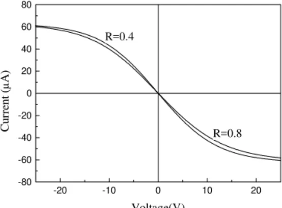
The situation which that the plasma parameters are iden-tical in the positions of the probes can be reproduced by positioning the probes side by side (s = 0). Fig. 2 shows the effect of the electron drift velocity on theoretical probe characteristic [eq. 12] for a double probe having two frontal electrodes when the distance between the probes (s) is zero(uniform plasma). For these fits the electron density used wasNe= 1017m−3and the electron temperature was
Te= 5 eV. If the plasma is uniform and if the plasma poten-tialsVP at the two probes are equals, then no current flows though the probe circuit at zero voltage (Va = 0, IdP = 0), because in this case the two probes are at the same floating potential.
-20 -10 0 10 20
-80 -60 -40 -20 0 20 40 60 80
R=0.8 R=0.4
Cu
rr
en
t (
µ
A)
Voltage(V)
Figure 2. Theoretical characteristic [eq. 12] of the double probe having two frontal electrodes in an uniform plasma. In order to evaluate only the electron drift velocity effect on each fit, all the other parameters involved in this simulation were kept fixed.
The double probe characteristic shown in Fig. 2 clearly shows that the electron drift velocity changes slightly the inclination of the characteristic curve. The double probe characteristic for non-uniform plasma is more complicated to obtain by simulation, because it involves the variation of many parameters. This part is discussed in the section 3 where probe data from a mercury arc discharge [6] are fitted for comparison with this theoretical model.
2.2
Floating potential
The floating potential of the double probe for a non-uniform plasma with drifting electrons, as considered here, is a func-tion of the angleθ, of the plasma potentialVP, of the elec-tron drift velocityvd and electron temperature Te in each position of the probes. As the model treated here is nonlin-ear, this function was evaluated in the limit whenB → 1
in eq. (12). The following equation is a good approxima-tion toVf whenR1cosθ1 →R2cosθ2because under this
conditions the dependency of the floating potential with the electron drift velocity is weak:
Vf = ∆VP−V1
µT
e2−Te1
Te1
+T02(R1cosθ1−R2cosθ2)
× "r
2V1
Te1 −
(R1cosθ1−R2cosθ2)
2
#
(16)
Thus, if the plasma is non-uniform and if it transports drifting electrons, to attain the floating potential of the dou-ble probe it is necessary to overcome, by the increase of the bias voltage of the probe not only the difference of plasma potential, but also, the potential difference due to the vari-ation of the electron temperature and also due to the dif-ference of the electron drift velocity in the positions of the probes.
IfR1cosθ1=R2cosθ2or if the anglesθare 90oin eq.
(16), we obtain a simple expression to the floating potential of the double probe:
Vf = ∆VP−αTe (17)
Here Vf = Vf2 − −Vf1, ∆Te = Te2 −Te1 and
α = V1/Te1 accounts for the drop in potential across the
probe sheath. According to the mercury positive-column theory, if the electrons and ions have both ideal maxwellian distribution functions, the expected values ofαis about 5.5. Under the existence of the drifting electrons, however, theα
parameter should be evaluated by including the effect of the drift velocity on the Bohm’s speed. As the equation (17) no has direct dependency with the electron drift velocity, it also can be obtained by analyzing the equation (8). Under these conditions,IdP=0 because the drops in potential across the sheath of the probe 1 (V1/Te1)is equal to that of the probe
2 (V2/Te2)and the probes collect the same amount of ions
and electrons current.
0 45 90 135 180
5 10 15 20 25 30 35 40
R=0.4 R = 0.7
R = 0.6
Floatin
g potential
(
V
)
θ2 (degree)
Figure 3. Effect of the electron drift velocity and of the angle θ2on the floating potential. In order to evaluate theReffect on
each fit, all the other parameters involved in the equation (16) were kept fixed. The curves were evaluated assumingR2 = R1 and
Te2 = Te1.The plasma parameters used for making this
simula-tion were: Te1 =Te2 = 7.0eV,N1 =N2 = 2.0×10 17
The effects of the electron drift velocity on the floating potential according the equation (16) is shown in the Fig. 3. The probe 1 was fixed at angleθ1= 0oand the angleθ2was
varied between zero and 180 degrees.
The floating potential is minimum with respect to the plasma potential when the collecting area of the probe 2 faces away the electron drift velocity (θ2 = 0). Fig. 3
clearly shows that the range of variation of the floating po-tential becomes larger by increasing the electron drift veloc-ity. Considering for the analysis of a single curve (Ris kept constant), that the electron axial velocity distribution func-tion is not symmetrical, the key point that must be recog-nized is that a large bias must be applied to repel the drifting electrons that contribute to the +Rcomponent (positive tail of maxwellian) of the double probe current, corresponding to the electron current flowing towards probe 1. Contrary effect occurs with respect the probe 2 when the angle θ2
approaches 180o. In this case the contribution of the elec-trons of the –Rcomponent (negative tail of the maxellian) of the double probe current, becomes lower and for the double probe to float (zero current), it needs to collect a lower ion flux, consequently the floating potential of the double probe approaches that of the plasma.
Although extrapolating the limits imposed by the model in computing these fits, the Fig. 3 shows that the results are consistent with works published by other authors [3,5]. In practice, however, effects of deformation of the plasma sheath and of drifting ions can generate significant discrep-ancies with respect to the theoretical model, mainly for an-glesθgreater than 90 degrees. These discrepancies are dis-cussed in 3.1.
2.3
Slope analysis
The probe theory suggests that the electron temperature and electron drift velocity can be estimated from the slope of the double probe characteristic atVf, because the slope of the characteristic curve is affected byTeandR[5]. Differen-tiating the equation (12) atVa =Vf and by expanding the complementary error function in an asymptotic series under the conditionR1cosθ1 =R2cosθ2, we obtain a good
ap-proximation for the slope of the double probe characteristic in a non-uniform plasma having drifting electrons:
·dI dp
dV
¸ Va=Vf
= Ii1Ii2
(Ii1+Ii2)Te2
Ãr 1
2αRcosθ−1
!
(18) Note that, ifR = 0 or ifθ = 90o, the slope has the al-ready known dependency on the electron temperature for a non-uniform plasma [1],
·
dIdp
dV
¸ Va=Vf
=− Ii
1Ii2
(Ii1+Ii2)Te2
. (19)
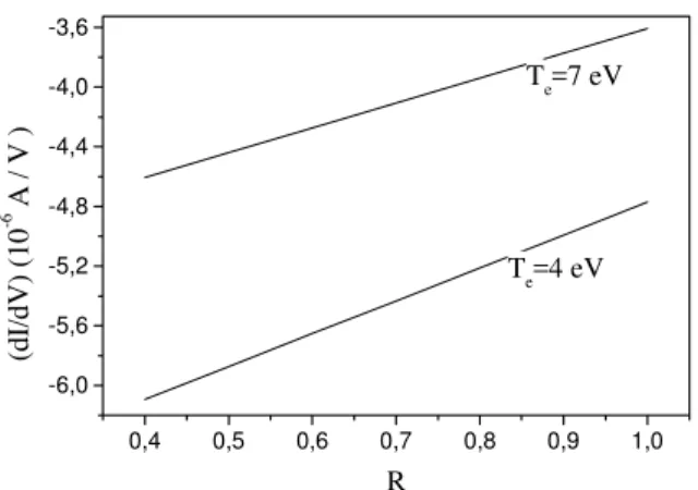
Figure 4 shows the effect of the electron drift velocity on the slope of the double probe characteristics computed by means of the equation (18) for frontal probes.
0,4 0,5 0,6 0,7 0,8 0,9 1,0 -6,0
-5,6 -5,2 -4,8 -4,4 -4,0 -3,6
Te=7 eV
Te=4 eV
(dI/
dV
) (10
-6 A /
V )
R
Figure 4. Effect of the electron drift velocity on the slope of the double probe characteristic for frontal probes configuration. In or-der to evaluate theReffect on each theoretical fit,Teis kept con-stant.
As the system float, the probe potential is always neg-ative with respect to the plasma potential. Consequently, the probe will collect only the electrons of the tail of the maxwellian. As result, the variation of the slope of the char-acteristic curve due to the effect of theRis small when com-pared with the effect due to the electron temperature. How-ever, as Fig. 4 shows, the drift changes almost linearly the slope of the characteristic curve; the larger the drift veloc-ity the gentler becomes the slope of the double probe, in the case of frontal probes.
3
Comparison with experiment
The experiments were performed in a discharge system sim-ilar to that of Maciel and Allen [3] (Fig. 5), where the con-cept of a single directional probe was reported. The dis-charge current and the distance between the probe positions in the plasma column were kept constant at 2 A and 0.51 m, respectively. The collecting area of the probes used were:
A1= 4.2×10− 6
m2
andA2= 3.4×10− 6
m2
.
to vacuum to vacuum
3.1
Floating potential
Figure 6 shows the variation of the experimental values (solid line) of the floating potential with the angleθ2when
the angleθ1 is kept fixed at 0o. For comparison, the fit to
the drifting electron model obtained by solving the equation (16) is indicated with dashed line.
0 45 90 135 180
4 8 12 16 20
Back to back probes Two frontal
probes
Floating poten
ti
al
(
V
)
θ2 (degree)
0 45 90 135 180
4 8 12 16 20
Figure 6. Comparison between the variation of the floating poten-tial with the angleθ2, predicted from the drifting electron model (eq.16) and the floating potential measured in a mercury arc dis-charge [6]. Experimental data are indicated with solid line and the fitting curve by the dashed line. For this fit the plasma param-eters used according to experimental results were: R1 = 0.52,
R2 = 0.50,Te1= 5.4eV,Te2= 4.4eV,N1= 1.85×10 17
m−3,
N2= 3.40×10 17
m−3,∆V
p= 1V.
The result of Fig. 6 shows that for anglesθhighest than 130o a disagreement between the two curves becomes ev-ident by reason of the electrons of the negative tail of the maxwellian which are collected in a amount greater than that estimated from the eq. (16). This effect implies an increase of the flotation potential with respect to the plasma poten-tial. Note in particular that the floating potential is signif-icantly overestimated by the theoretical model for the case of back to back probes. Deformation of the probe sheath, considered to be plane in our model, is no longer valid in this range of angleθ2.Additionally, as the configuration
ap-proaches that of back to back probes the effect of the ion drift velocity towards probe 2 is also conceivable to con-tribute to the discrepancies between the curves of Fig. 6. This observation suggests that an improvement of the model could be achieved by considering, in the theory, the effect of the ion and electron drift velocities on the Bohm’s speed whenTe<< Ti. Thus, for the analysis presented in the next section, we have restricted to the case of the frontal probes configuration, where the effects explained above is not im-portant because the probes receive equal ion saturation cur-rent.
3.2
Double probe characteristics for the
frontal probe configuration
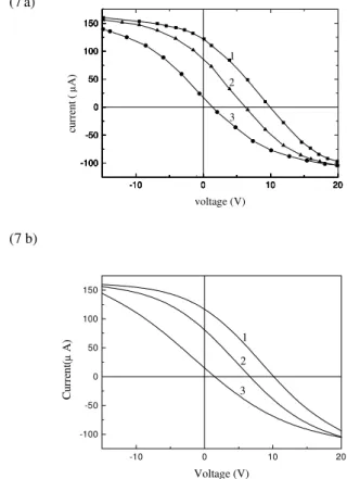
Figure 7(a) shows the experimental characteristic of the dou-ble probe made of two frontal probes. For comparison, the
theoretical curves are shown in figure 7(b). In these curves, the plasma parameters were adjusted by a fitting method to give the same floating potential and slope of the experimen-tal double probe characteristic. An interactive method based on the general double probe characteristic equation (eq. 12) was performed leading to the determination of the remain-ing plasma parameters comprised in the theoretical probe characteristic equation.
(7a)
(7 b)
-10 0 10 20
-100 -50 0 50 100 150
3 2 1
Cu
rr
en
t(
µ
A)
Voltage (V)
-10 0 10 20
-100 -50 0 50 100 150
3 2 1
cu
rr
en
t (
µ
A)
voltage (V)
-10 0 10 20
-100 -50 0 50 100 150
-10 0 10 20
-100 -50 0 50 100 150
-10 0 10 20
-100 -50 0 50 100 150
-10 0 10 20
-100 -50 0 50 100 150
Figure 7. a) Experimental and b) theoretical characteristic of the double probe having frontal probe configuration. The distance be-tween the probe was kept fixed at 0.51 m. In this case the plasma parameters converge to: curve 1: R1 = 0.42,R2 = 0.40,Te1 = 5.3eV,Te2= 4,3eV,N1= 1.85×10
17
m−3,N
2= 3.45×10 17
m−3,∆V
p= 4.3V. curve 2:R1 = 0.52,R2= 0.50,Te1= 5.4
eV,Te2 = 4,4eV,N1 = 1.85×10 17
m−3,N2 = 3.40×10¹⁷
m−3,∆V
p= 1V. curve 3:R1 = 0.76,R2= 0.75,Te1= 5.6eV,
Te2= 5.5eV,N1 = 1.83×10 17
m−3,N2 = 3.40×10¹⁷m−3, ∆Vp= 0.7V.
These plasma parameters obtained by the numerical fit-ting are consistent with the experimental data taken in a low mercury arc discharge, as depicted in Fig. 6. Note that theR values at the probe positions are approximately equals according to experimental data [6]. In this reference, it is shown that the difference between each parameter∆e and∆N is significant only for lowerR-values. When the plasma becomes more uniform (curve 3), the floating poten-tial of the two frontal probes is acceptable as being the dif-ference of the plasma potential at the positions of the probes (∆VP), as already discussed in 2.1.
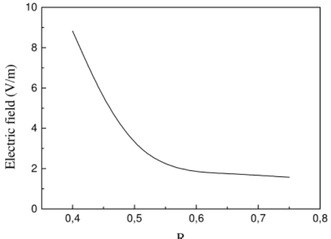
plasma potential, according to eq.(16). This result, when di-vided by the distance between the probes (s=0.51 m) gives an estimation of the axial electric field along the plasma col-umn. Fig. 9 shows clearly that the axial electric field is a decreasing function of the electron drift velocity. AsR1and
R2have almost equal values, we have taken the mean value
ofRto draw the Figs. 8 and 9.
0,3 0,4 0,5 0,6 0,7 0,8 0
5
10 Vf-Frontal probes
∆VP-Theory
Po
tential (
V
)
R
Figure 8. Effect of the electron drift velocity on the floating poten-tial of the double probe. Experimental data(solid line) was taken from the figure 7 (a) and the dashed line indicates the plasma po-tential variation computed by equation (16) forTe1> Te2.
0,4 0,5 0,6 0,7 0,8 0
2 4 6 8 10
E
le
ctr
ic
f
ield
(
V
/m
)
R
Figure 9. Axial electric field of the plasma column as a function of the electron drift velocity.
4
Conclusion
The directional double probe studies developed in this work consider a plasma in which electrons have a drifted maxwellian distribution. The distance between the probes is very large such that the plasma parameters could be dif-ferent, where the probes are located. The magnitude of the drift is represented by he ratio of the electron drift velocity to thermal velocity (R). A general equation for the dou-ble probe characteristic is deduced. For practical use of the
double probe, we deduced analytical relations in which are shown the direct dependency of the floating potential and of the slope of the double probe characteristic upon theR
parameter.
Data from a plasma column of a low-pressure mercury arc discharge were used to proceed an interactive method in order to fit experimental characteristic curves with theo-retical ones. The results show good agreement for the case of frontal probes configuration. This technique was espe-cially applied to verify the effects of the electron drift ve-locity on the plasma potential and on the axial electric field along the positive column. As other applicability, depend-ing on the nature of the gas, this theory could be used in various cold plasma reactors where non-uniform plasmas are usually produced. An application of this double probe technique could be the measurements of∆Te and∆VP in the different regions of a discharge as for example in the different plasmas formed in the H mode [7] generated in a inductively r.f plasma reactor. Also, this technique could be used to characterize quiescent plasmas generated in dou-ble plasma machines [8], where two different plasmas are separated by polarization grids. In this case, theR-values of the plasmas could be made different by acceleration of electrons and ions by means of the grids. This effect also occurs in plasma jet reactors [9] based in a glow discharge plasma column where a plasma beam is generated by a geo-metric constriction of the discharge tube. However, in most of these examples, the plasma parameters in the region be-tween the probes, are non-uniform. Thus, a spatial profile of these parameters could be obtained by varying the distance between the probes.
References
[1] F.F. Chen,inPlasma Diagnostic Techniques(Academic, New York, 1965) p. 136.
[2] J.D. Swift, and Schar, inElectrical probes for plasma diag-nostic(M.J.R. Iliffe Books Ltd, London, 1970) 137.
[3] H.S. Maciel, and J.E. Allen, J. Plasma Physics 42, 321 (1989).
[4] G. Petraconi, H.S. Maciel, and M. Uehara, Fourth Sympo-sium on Double Layers and Other Nonlinear Potential Struc-tures in Plasma,Innsbruch, Roman W. Schrittwieser Ed. 244 (1992).
[5] S. Ariga, Journal of the Physical Society of Japan, 31, 4, 1221(1971).
[6] G. Petraconi,et. al.To be published.
[7] J. Amorin, Journal Vac. Sci. Technology, B902, 362 (1991).
[8] G. Hassal and J.E. Allen, J. Phys. D: Appl. Phys.30, 381 (1997).