ISSN 0104-6632 Printed in Brazil
www.abeq.org.br/bjche
Vol. 33, No. 03, pp. 567 - 576, July - September, 2016 dx.doi.org/10.1590/0104-6632.20160333s20150074
Brazilian Journal
of Chemical
Engineering
CHARACTERISATION OF ASYMMETRIC
ALUMINA HOLLOW FIBRES: APPLICATION
FOR HYDROGEN PERMEATION IN
COMPOSITE MEMBRANES
N. M. Terra, C. O. T. Lemos, F. B. da Silva, V. L Cardoso and M. H. M. Reis
*Universidade Federal de Uberlândia, Faculdade de Engenharia Química, Av. João Naves de Ávila 2121, Zip Code: 38048100, Uberlândia - MG, Brazil.
E-mail: [email protected]
(Submitted: February 7, 2015 ; Revised: July 27, 2015 ; Accepted: August 6, 2015)
Abstract - Asymmetric alumina hollow fibres produced by the phase inversion/sintering method present advantages in that high area/volume ratios and low mass transfer resistances are achieved due to the geometric configuration and the pore size distribution, respectively. Here we characterise hollow fibres that were prepared with different internal coagulants and at different sintering temperatures. Additionally, a palladium membrane was deposited on these different hollow fibres and hydrogen permeabilities through them were compared. More fingers were obtained when a mixture of solvent with water was used as internal coagulant, instead of pure water. At the same sintering temperature, nitrogen permeance through the fibre was increased 5-fold when a mixture of solvent and water was used as internal coagulant instead of pure solvent, and the water flux was increased 7-fold. The decrease in the sintering temperature increased the water permeance
through the fibre from 21.4 to 63.9 L h-1 m-2 kPa-1, but decreased its mechanical strength from 74 to 41 MPa.
The hydrogen permeance at 450 °C was increased from 5.54x10⁻⁵ to 3.06 x10⁻³ mol m-2 s-1 kPa-1 when using a
more permeable hollow fibre as substrate. These results elucidate better conditions to fabricate hollow fibres that present low mass transfer resistances.
Keywords: Asymmetric hollow fibres; Composite palladium membranes; Hydrogen permeation.
INTRODUCTION
Membrane separation processes have been widely used in different areas such as chemical, food and pharmaceutical industries. Depending on the desired application, membranes can be synthesized from different materials, in different geometries and with symmetric or asymmetric pore size distributions. Ceramic membranes in a hollow fibre configuration present some advantages due to the high chemical, thermal and mechanical resistances of the applied material, in addition to the membrane geometry that enables a large surface area per unit volume of a
membrane module.
immer-sion induced phase inverimmer-sion technique applied in the production of polymeric membranes, the for-mation of ceramic asymmetric membranes occurs due to the hydrodynamically unstable viscous finger-ing phenomena, since a high viscous suspension is in contact with a low viscous hydrophilic nonsolvent (Wei, et al., 2008). Hydrodynamically unstable vis-cous fingering is a well-known phenomenon that occurs at the interface between fluids with different viscosities in the first moment of mixing. For ceramic membranes, the dry-wet spinning and phase-inversion technique is followed by a sintering process.
Asymmetric membranes present at least two main regions of different pore sizes: a sponge-like layer with smaller pore sizes and a region with micro-channels of larger pore sizes. The sponge-like layer ensures the necessary mechanical strength for the membrane. Thus, the asymmetric pore structure with an outer sponge layer and an inner layer with larger filaments presents favourable characteristics for higher permeations (Garcia-Garcia et al., 2011).
Characteristics of asymmetric ceramic mem-branes are mainly influenced by process parameters such as suspension composition, air gap, extrusion rate, bore liquid flow rate and sintering temperature (Lee et al., 2014; Liu et al., 2003; Sun et al., 2006; Kingsbury and Li, 2009; Li et al., 2006). Garcia-Garcia et al. (2011 2012) showed that the increase in the sintering temperature increased the bending strength of the membrane but decreased its perability. Therefore, there is a trade-off between me-chanical strength and gas permeability and this choice must be deeply analysed.
Composite palladium (Pd) membranes can be applied for hydrogen purification in an integrated membrane reactor system (Yun and Oyama, 2011). However, one of the main drawbacks in this applica-tion is the increase in the hydrogen permeability (Dittmeyer et al., 2001). This increase can be achieved by reducing the palladium thickness, but without loss of the membrane selectivity. Moreover, the substrate used for the palladium deposition must present low mass transfer resistance, but confer the necessary mechanical strength to the composite membrane. Asymmetric hollow fibres can be potentially applied as a substrate for palladium membrane depositions due to their smooth outer layer and low mass transfer resistance (Hatim et al., 2011).
The main objective of this research was to evalu-ate the characteristics of alumina (Al2O3) hollow fibres prepared using different sintering temperatures and internal coagulant compositions. These hollow fibres were characterised according to their
morphol-ogy, roughness, mechanical strength, and water and nitrogen permeabilities. Additionally, a comparison of hydrogen permeabilities through composite Pd/Al2O3 membranes that were prepared using dif-ferent hollow fibres as supports was carried out.
MATERIAL AND METHODS
Material
Ceramic hollow fibre substrates were fabricated using aluminium oxide powder of 1.0 µm (alpha, 99.9% metal basis, surface area 6-8 m2 g-1) pur-chased from Alfa Aesar. The ceramic suspension was prepared using Polyethersulfone (PESf, Radel A-300, Ameco Performance, USA), dimethyl sulfoxide (DMSO, VWR) and Arlacel P135 (Uniqema, UK) as polymer binder, solvent and additive, respectively.
Tin(II) chloride dihydrate (puriss. p.a., Aldrich) and palladium(II) chloride (99.999%, Sigma-Aldrich) were mixed with hydrochloric acid (37%, AnalaR NORMAPUR) to prepare the sensitisation and activation solutions, respectively. The plating solution was prepared using tetraamminepalladium(II) chloride monohydrate (99.99% metals basis, Sigma-Aldrich), EDTA (IDRANAL®III, Riedel-deHaen), ammonium hydroxide (28% in H2O, Sigma-Aldrich) and hydrazine hydrate (Sigma-Aldrich).
Fabrication of Asymmetric Al2O3 Hollow Fibres
Asymmetric Al2O3 hollow fibres were fabricated using the phase inversion/sintering method (Kingsbury and Li, 2009). Arlacel P135 was dissolved in DMSO prior to the addition of aluminium oxide. The mix-ture was rolled/milled for 48 h. After this, the poly-mer was added to the mixture and the suspension was rolled/milled for a further 48 h. The suspension was then transferred to a gas tight reservoir and de-gassed under vacuum. After degassing, the spinning suspension was extruded through a tube-in-orifice spinneret (outer diameter 3 mm, inner diameter 1.2 mm) into the external coagulation bath with water at different air gaps (distance between the fibre precur-sor and the external coagulant bath). Extrusion rates of 7 and 5 mL·min-1 were adopted for the ceramic suspension and bore fluid, respectively.
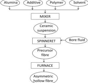
TSH 17/75/450). In the sintering process, the tem-perature was increased up to 600 °C at a rate of 2 °C min-1 followed by a dwell of 2 h. In a second stage, the temperature was increased up to 1300 or 1400 °C (target temperature) at a rate of 5 °C min-1 followed by a dwell of 4 h. After that, the temperature was decreased to 25 °C at a rate of 3 °C min-1. Figure 1 presents a flowchart with the steps carried out for the asymmetric hollow fibre preparation.
Figure 1: Flowchart of the spinning process.
The different parameters applied in the fabrica-tion of each fibre are described in Table 1. The fibre HF1-1400 was prepared using water as the internal coagulant. Water is responsible for the coagulation of the ceramic suspension and, consequently, for the formation of micro-voids across the fibre. Using water as internal and external coagulants (Fibre HF1-1400) an air gap is necessary in order to allow the formation of the sponge-like layer in the outer surface of the fibre; otherwise the micro-voids would be formed in the inner and outer surfaces of the fibre. The fibre HF1-1400 was sintered at 1400 °C. No air gap was used during the fabrication of the fibres HF2-1300, HF3-1300 and HF3-1400 since solvent or a mixture of solvent with water were used as the internal coagulants. In these fibres (HF2-1300, HF3-1300 and HF3-1400) the micro-void formation was from the outer to the inner surface of the fibre due to the action of water that was used as external coagu-lant. The use of solvent as internal coagulant pre-vents precipitation or increased local viscosity at the inner surface before the solvent is finally exhausted. The fibre HF2-1300 was sintered at 1300 °C. For the fibres HF3-1300 and HF3-1400 the applied sintering temperatures were 1300 and 1400 °C, respectively.
Table 1: Fabrication parameters of the fibres.
Fibre Internal Coagulant
Air Gap (cm)
Sintering Temperature
(°C)
HF1-1400 Water 3 1400 HF2-1300 Solvent 0 1300
HF3-1300 Solvent+Water 0 1300
HF3-1400 Solvent+Water 0 1400
Characterisations of Asymmetric Al2O3 Hollow
Fibres
The microstructure of each produced hollow fibre was characterized by scanning electron microscopy (EVO MA 10, Carl Zeiss). The surface micrograph and the average roughness of the hollow fibres were verified using atomic force microscopy (AFM, Shi-madzu, SPM-9600).
The bending strength (F) of the hollow fibres
was determined by the bending test using an Instron Model 4466 provided with a load cell for 1 kN and was calculated using Equation (1) (Cernica, 1977; Othman et al., 2010).
4 4
8 o
F
o i
FLD
σ
D D
(1)
where F is the measured load in which the fracture occurred (N), L is the length of the sample (m), and
Do and Di are the outer and the inner diameters of the
sample, respectively.
m
J
A t (2)
where J is the flux (kg m−2 s−1), m is the permeated mass (kg), A is the effective surface area of the fibre (m2) and t is the time of the permeate collection (s).
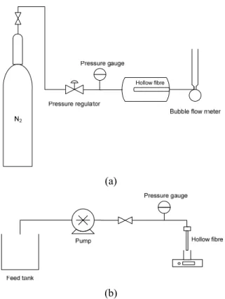
(a)
(b)
Figure 2: Schematic diagram of the nitrogen (a) and
water (b) permeation apparatus.
Electroless Plating Procedure for Palladium Coat-ing on Asymmetric Hollow Fibre Substrates
Palladium membranes were coated onto the outer surface of asymmetric hollow fibre substrates using the electroless plating procedure (Paglieri and Way, 2002; Mardilovich et al., 1998). The coating was carried out on a length of 7 cm of the fibre and the ends of the fibre were coated with a gas-tight glaze.
According to the electroless plating procedure, the substrates were first activated with Pd nuclei via sensitisation in an acidic SnCl2 solution followed by activation in an acidic PdCl2 solution. The sensitisa-tion/activation process was carried out by immersing the glazed hollow fibre substrates sequentially in five chemical baths: acidic SnCl2 solution for 5 min; deionised water for 5 min, acidic PdCl2 solution for 5 min; 0.01 M HCl solution for 2 min; and finally de-ionised water for 3 min. All chemical baths were homogenised with air bubbles. The sensitisation/
activation process was repeated for 8 cycles. The composition of each bath is presented in Table 2.
Table 2: Sensitisation, activation and plating bath compositions.
Step Compound Concentration
Sensitisation SnCl2 1 g L-1
HCl (37%) 1 mL L-1
Activation PdCl2 0.1 g L-1
HCl (37%) 1 mL L-1
Rinsing HCl 0.01M
Electroless Plating
Pd(NH3)4Cl2-H2O 4 g L-1
Na2EDTA-2H2O 40.1 g L-1
NH3-H2O (28%) 198 mL L-1
N2H4 (1M) 5.6 mL L-1
After the sensitisation/activation step, the sub-strates were immersed in a Pd electroless plating solution at 60 °C for 60 min in order to deposit me-tallic Pd layers onto the activated surface. The plat-ing solution was prepared accordplat-ing to the composi-tion presented in Table 2 using a volume of 3.5 mL per cm2 of substrate surface area, as suggested by Mardilovich et al. (1998).
The thicknesses and the roughness of the mem-branes were measured using SEM and AFM images, respectively.
Hydrogen Permeation Through Pd/Al2O3
Compo-site Hollow Fibre Membranes
Hydrogen (H2) permeation measurements were performed using the experimental apparatus shown in Figure 3. The Pd/Al2O3 composite hollow fibre membrane with one-end sealed was glued to a stain-less steel holder using epoxy-resin (Araldite®) and then introduced into a stainless steel tube. This tube was placed centred in a tubular furnace (CARBO-LITE, MTF 10/25/130) and connected to inlet and outlet streams. The permeate flow rate was moni-tored by a bubble flow meter and the feed pressure was adjusted using a pressure regulator (OMEGA, PRG101-120) and monitored by a pressure gauge with a resolution of 0.1 psi (OMEGA, DPG1000B-10G).
Figure 3: Schematic representation of the apparatus used for hydrogen permeation tests.
The system temperature was increased up to 450 °C at a heating rate of 3 °C min-1 under nitrogen purge at atmospheric pressure. The decrease of the tem-perature was carried out at a rate of 3 °C min-1 under nitrogen purge and membrane integrity was evalu-ated at each temperature for pressures up to 300 kPa. Hydrogen permeation tests were conducted exclu-sively on membranes which were gas-tight to nitrogen.
RESULTS AND DISCUSSION
Comparison of Asymmetric Hollow Fibres Pre-pared Under Different Conditions
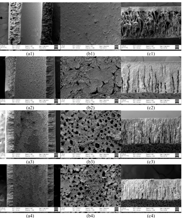
Figure 4 shows the SEM images of each pro-duced fibre. The obtained hollow fibres presented the desired asymmetric morphological structure, with an outer sponge-like layer and inner micro-channels covering a large extension of the fibre. The inner micro-channels will ensure greater permeabilities through the fibre. The outer sponge like layer is denser than the inner micro-channels and will pro-vide the required mechanical strength for the hollow fibre.
Depending on the applied sintering temperature and the internal coagulant used, the obtained hollow fibres presented different morphological aspects. When water is used as internal coagulant an air gap is necessary to form the external sponge-like layer due to the contact of the outer surface of the fibre with air that increases the viscosity at this surface, as shown in Figure 4(c1). Then the fibre is immersed in the coagulation bath containing water, but the growth of the finger-like voids from the outer surface of the fibre is inhibited due to the previous increase in the
viscosity. The inner surface of the fibre is in contact with water since the suspension is extruded and hence phase inversion and the formation of fingers are initiated there. Figures 4(a1) and 4(b1) show that the micro-channels of the hollow fibre HF1-1400 were blocked in the inner layer of the fibre. Applica-tion of water as the internal coagulant can be re-sponsible for a ceramic precipitation that blocked the formed micro-channels. This blockage will decrease the fibre permeability, besides making difficult the application of this fibre as a support for catalyst depositions, for instance. In fact, for this fibre (HF1-1400), there are two sponge-like layers, one inside and the other outside the fibre. Figure 4(c1) shows that the filaments were formed irregularly and not along the fibre. Moreover, the finger-like layer is dense and covers approximately 20% of the fibre extension.
When solvent is used as internal coagulant the outer surface of the fibre is directly immersed in the coagulation bath containing water (zero air gap) and an instantaneous precipitation occurs from the outer surface. The use of solvent as internal coagulant prevents precipitation or increased local viscosity at the inner surface before the solvent is finally ex-hausted. According to Figures 4(a2) and 4(b2), the fibre HF2-1300 has a structure of micro-channels that were opened in the inner layer of the fibre since solvent was used as internal coagulant instead of pure water, and the ceramic precipitation was mini-mised. Comparing Figures 4(c2) and 4(c1), it is possible to see that the micro-channels formed in the fibre HF2-1300 are thinner and more regular than those formed in the fibre HF1-1400 due to the action of the solvent as internal coagulant. However, the number of micro-channels formed in the fibre HF2-1300 was smaller than in the other fibres. When using solvent as internal coagulant, the filaments are formed from the outer to the inner surface of the fibre due to the presence of water in the external bath. Thus, application of pure solvent as internal coagulant did not ensure the formation of numerous micro-voids across the fibre.
(a1) (b1) (c1)
(a2) (b2) (c2)
(a3) (b3) (c3)
(a4) (b4) (c4)
Figure 4: (a) Cross section, (b) inner surface and (c) fibre wall SEM images of the hollow
fibres (1) HF1-1400, (2) HF2-1300, (3) HF3-1300, (4) HF3-1400.
micro-channels of the fibres 1300 and HF3-1400 were also partially blocked, as shown in Figures 4(b3) and 4(b4). Then, the morphological analysis of the produced fibres showed that longer, organized and numerous micro-channels are obtained when using a mixture of solvent with water as internal co-agulant, and, since no pure water was used as inter-nal coagulant, the micro-channels remained partially open in the inner surface of the fibre. Figures 4(c3) and 4(c4) show that when a mixture of solvent with water is used as internal coagulant some fingers are formed from the inner surface and thus, more fingers
are obtained.
(a)
(b)
(c)
Figure 5: AFM images of the hollow-fibres (a)
HF1-1400, (b) HF2-1300 and (c) HF3-1300.
According to the AFM images, mean and square roughness (Ra and Rq, respectively) were calculated for each hollow fibre (Table 3). The fibre HF1-1400 presented the smallest surface roughness, followed by the fibres HF3-1300 and HF2-1300. Thus, the use
of water as internal coagulant probably decreased the roughness of the outer surface of the fibre due to the formation of the micro-voids from the inner to the outer surface of the fibre. Moreover, as also observed by Wei et al. (2008), the increase in the sintering temperature (fibres HF1-1400 and HF2-1300) could have decreased the roughness of the outer surface of the fibre due to the higher densification of the sponge-like layer at higher temperatures.
Table 3: Mean and square roughness (Ra and Rq, respectively) of each hollow fiber for a scan area of 10×10 µm.
Sample Ra (nm)
Rq (nm)
HF1-1400 87.56 110.56
HF2-1300 125.72 158.65
HF3-1300 100.86 124.71
The mechanical strengths of the fibres HF1-1400, HF2-1300, HF3-1300 and HF3-1400 were equal to 70.3, 55.5, 41.2 and 74.5 MPa, respectively. Although all fibres presented high porosity, they did not pre-sent a high fragility. In fact, the fragility of the fibres increased with the increase of the micro-channel re-gion. Moreover, related to the densification of the sponge-like layer, the decrease in the sintering tem-perature decreased the mechanical strength of the hollow fibre. Sun et al. (2006) produced asymmetric hollow fibres using different internal and external coagulant concentrations and obtained fibres with mechanical strengths varying from 36.3 to 122.6 MPa. However, the highest mechanical strength reported by Sun et al. (2006) (122.6 MPa) was attributed to a fibre without micro-channels.
Table 4 presents the measured water flow rate through the fibres according to the transmembrane pressure. The areas of the hollow fibres HF1-1400, HF2-1300, HF3-1300 and HF3-1400 used in these measurements were 7.10, 2.16, 4.95 and 4.32 cm2, respectively. These data were used to calculate the water flux according to Equation (2).
Table 4: Measured water flow rate through the fibres according to the pressure.
Pressure (psi)
Water flow rate (L h-1)
HF1-1400 HF2-1300 HF3-1300 HF3-1400
4 0.023 0.058 0.780 0.193 6 0.040 0.087 1.236 0.314 8 0.054 0.118 1.812 0.460 10 0.072 0.144 2.208 0.596 12 0.093 0.167 2.610 0.753 14 0.111 0.194 3.024 0.899
Figure 6 shows nitrogen permeance and water flux through the fibres. The gas flow through the fibre HF3-1300 was not measured since it was higher than the maximum value measured by the rotameter (10 L min-1) even at lower pressures.
(a)
(b)
Figure 6: (a) Nitrogen permeance and (b) water flux
through the hollow fibres HF1-1400, HF2-1300, HF3-1300 and HF3-1400.
The fibre HF3-1400, which has more filaments, presented the highest gas permeability (Figure 6a). It is important to consider that this fibre presented a relative high mechanical strength, due to the higher applied sintering temperature. The lowest N2 perme-ability was observed for the fibre HF1-1400, proba-bly due to the blockage of the micro-channels in the inner layer. The values of N2 permeation through the fibre HF1-1400 are in agreement with values re-ported by Hatim et al. (2011) for a similar asymmet-ric hollow fibre.
Figure 6b shows the water flux through the pro-posed hollow fibres. All fluxes presented a linear behaviour with the pressure. The greater water flow was verified through the fibre HF3-1300, probably because of the greater length and the number of micro-channels. Comparing the water flow through the fibres HF3-1300 and HF3-1400, it is possible to verify that the increase in the sintering temperature decreased the permeability of the fibre by
approxi-mately 2%, due to the densification of the sponge-like layer. Similarly for gas permeation, the fibre HF3-1400 presented higher water permeability than the fibres HF2-1300 and HF1-1400. Wu et al. (2013) evaluated the water flow through an asymmetric hol-low fibre with similar structure to HF1-1400. Values of water flow through the fibre HF1-1400 are in agreement with the values given by Wu et al. (2013).
Effect of the Substrate on Hydrogen Permeation Through Composite Palladium Membranes
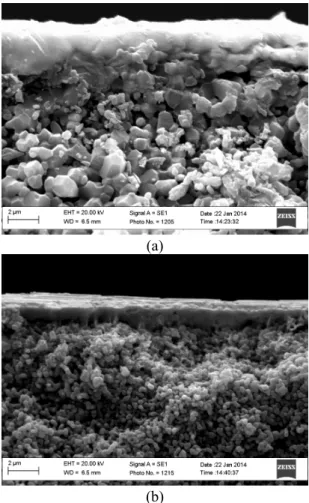
The hydrogen flow rate was measured through composite Pd/Al2O3 membranes using as substrate the asymmetric hollow fibres HF1-1400 and HF3-1400. According to the SEM images (Figure 7), the coated Pd membranes presented thicknesses of 1.8 and 1.4 µm using the hollow fibres HF1-1400 and HF3-1400 as supports, respectively. The Pd coating was carried out in separated baths, so that this differ-ence in the thickness could be expected even using identical electroless plating conditions.
(a)
(b)
Figure 7: Cross-section SEM images of the
asym-metric Pd/Al2O3 composite membranes supported on the hollow fibres HF1-1400 (a) and HF3-1400 (b). 0
50 100 150 200 250 300
0 20 40 60 80 100
N2
P
e
rm
e
a
n
ce
(m
m
o
l
m
‐
2s
‐
1P
a
‐
1)
Pressure (kPa)
HF1‐1400 HF2‐1300 HF3‐1400
y = 1.5529x
R² = 0.9776
y = 8.5338x
R² = 0.9851
y = 63.879x
R² = 0.9980
y = 21.444x
R² = 0.9885
0 1000 2000 3000 4000 5000 6000 7000 8000
0 20 40 60 80 100 120
W
a
te
r
fl
u
x
(L
h
‐
1m
‐
2)
Pressure (kPa)
Figure 8 presents the AFM image of the fibre HF1-1400 after the coating with Pd. Comparing Figures 5(a) and 8, it is possible to see that the outer surface of the membrane becomes smoother after the Pd deposition. Values of mean and square roughness for the Pd/HF1-1400 composite membrane were 67.21 and 83.13 nm, respectively, which represent values 1.3 times greater than for the substrate used.
Figure 8: AFM image of the asymmetric Pd/Al2O3
composite membranes supported on the hollow fibre HF1-1400.
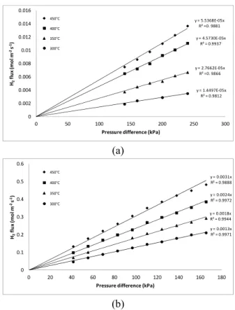
Figure 9 presents the H2 permeation through the composite membranes prepared using HF1-1400 and HF3-1400 as substrates. The linear adjustment of H2 flux with pressure was better than the adjustment according to Sievert’s law (n=0.5), since the surface adsorption/desorption becomes the controlling step instead of bulk diffusion (Yun and Oyama, 2011).
Hydrogen flux increased with increases in the temperature and in the transmembrane pressure. Hy-drogen permeances through the composite mem-brane prepared using the hollow fibre HF3-1400 as substrate was approximately 60 times greater than using the hollow fibre HF1-1400. The composite membrane Pd/ HF1-1400 reached a H2 flux similar to the highest ones reported in the literature (0.40 mol m-2 s-1 at 100 kPa and 450 °C for composite membranes using ceramic supports (Yun et al., 2011; Zhao et al., 1998). However, Yun et al. (2011) and Zhao et al. (1998) applied a modified electroless pro-cedure in order to deposit thinner and selective Pd membranes on the ceramic supports.
Then, application of Al2O3/Pd asymmetric hollow fibre composite membranes presents advantages for hydrogen permeation of higher ratios of area and volume and less resistance to mass transfer.
(a)
(b)
Figure 9: Hydrogen flux through asymmetric Pd/Al2O3
composite hollow fibre membranes supported on HF1-1400 (a) and HF3-1400 (b).
CONCLUSION
The proposed hollow fibres presented the re-quired properties: high mechanical strength, smooth outer surface, presence of micro-channels in a large extension of the fibre, high porosity, and high nitro-gen and water permeabilities. The decrease in the sintering temperature, from 1400 to 1300 °C, increased the permeabilities through the fibre. However, the decrease in the sintering temperature decreased the mechanical strength of the hollow fibre.
Moreover, the choice of the appropriate internal coagulant, responsible for the formation of the micro-channels, is important to have a more permeable hollow fibre. Characterisation results showed that the application of a mixture of water and solvent as internal coagulant for the fabrication of hollow fibres ensured the formation of numerous and long micro-channels that, consequently, resulted in high permea-bilities through these fibres.
Hydrogen permeation measurements through composite Pd/Al2O3 membranes showed that the support employed has a great influence on the result obtained.
y = 5.5368E‐05x R² =0. 9881
y = 4.5730E‐05x R² = 0.9937
y = 2.7662E‐05x R² =0. 9866
y = 1.4497E‐05x R² = 0.9812
0 0.002 0.004 0.006 0.008 0.01 0.012 0.014 0.016
0 50 100 150 200 250 300
H2 fl u x (m o l m ‐ 2 s ‐ 1)
Pressure difference (kPa) 450°C
400°C 350°C 300°C
y = 0.0031x R² = 0.9888
y = 0.0024x R² = 0.9972
y = 0.0018x R² = 0.9944
y = 0.0013x R² = 0.9971
0 0.1 0.2 0.3 0.4 0.5 0.6
0 20 40 60 80 100 120 140 160 180
H2 fl u x (m o l m ‐ 2 s ‐ 1)
Pressure difference (kPa)
450°C
400°C
350°C
ACKNOWLEDGMENTS
The authors acknowledge Professor Kang Li for supporting hollow fibre preparations and the research funding provided by CNPq (Grant number: 407133/ 2013-5), CAPES and FAPEMIG (Grant numbers: TEC-PPM-00752-15 and TEC-APQ-01750-15).
REFERENCES
Cernica, J. N., Strength of Materials. 2nd Edition Ed., Holt Rinehart & Winston, New York (1977). de Jong, J., Benes, N. E., Koops, G. H., Wessling,
M., Towards single step production of multi-layer inorganic hollow fibers. Journal of Membrane Science, 239, pp. 265-269 (2004).
Dittmeyer, R., Hollein, V., Daub, K., Membrane reactors for hydrogenation and dehydrogenation processes based on supported palladium. J. Mol. Catal. A-Chem., 173, pp. 135-184 (2001).
Falbo, F., Tasselli, F., Brunetti, A., Drioli, E., Barbieri, G., Polyimide hollow fiber membranes for CO2 separation from wet gas mixtures. Braz. J. Chem. Eng., 31, pp. 1023-1034 (2014).
Garcia-Garcia, F. R., Kingsbury, B. F. K., Rahman, M. A., Li, K., Asymmetric ceramic hollow fibres applied in heterogeneous catalytic gas phase reactions. Catalysis Today, 193, pp. 20-30 (2012). Garcia-Garcia, F. R., Rahman, M. A., Kingsbury, B.
F. K., Li, K., Asymmetric ceramic hollow fibres: New micro-supports for gas-phase catalytic reac-tions. Applied Catalysis A-General, 393, pp. 71-77 (2011).
Hatim, M. D. I., Tan, X. Y., Wu, Z. T., Li, K., Pd/Al2O3 composite hollow fibre membranes: Effect of substrate resistances on H-2 permeation properties. Chemical Engineering Science, 66, pp. 1150-1158 (2011).
Kingsbury, B. F. K., Li, K., A morphological study of ceramic hollow fibre membranes. Journal of Membrane Science, 328, pp. 134-140 (2009). Lee, M., Wu, Z. T., Wang, R., Li, K.,
Micro-struc-tured alumina hollow fibre membranes - Potential applications in wastewater treatment. Journal of Membrane Science, 461, pp. 39-48 (2014). Li, K., Tan, X. Y., Liu, Y. T., Single-step fabrication of
ceramic hollow fibers for oxygen permeation. Journal of Membrane Science, 272, pp. 1-5 (2006). Liu, S. M., Li, K., Hughes, R., Preparation of porous
aluminium oxide (Al2O3) hollow fibre mem-branes by a combined phase-inversion and sin-tering method. Ceramics International, 29, pp. 875-881 (2003).
Machado, P. S. T., Habert, A. C., Borges, C. P., Mem-brane formation mechanism based on precipita-tion kinetics and membrane morphology: Flat and hollow fiber polysulfone membranes. Journal of Membrane Science, 155, pp. 171-183 (1999). Mardilovich, P. P., She, Y., Ma, Y. H., Rei, M. H.,
Defect-free palladium membranes on porous stainless-steel support. AIChE Journal, 44, pp. 310-322 (1998).
Othman, M. H. D., Wu, Z. T., Droushiotis, N., Do-raswami, U., Kelsall, G., Li, K., Single-step fabri-cation and characterisations of electrolyte/anode dual-layer hollow fibres for micro-tubular solid oxide fuel cells. Journal of Membrane Science, 351, pp. 196-204 (2010).
Paglieri, S. N., Way, J. D., Innovations in palladium membrane research. Separ Purif. Method, 31, pp. 1-169 (2002).
Sun, G. B., Hidajat, K., Kawi, S., Ultra thin Pd mem-brane on alpha-Al2O3 hollow fiber by electroless plating: High permeance and selectivity. Journal of Membrane Science, 284, pp. 110-119 (2006). Tan, X. Y., Liu, S. M., Li, K., Preparation and
char-acterization of inorganic hollow fiber membranes. Journal of Membrane Science, 188, pp. 87-95 (2001).
Wei, C. C., Chen, O. Y., Liu, Y., Li, K., Ceramic asymmetric hollow fibre membranes-One step fabrication process. Journal of Membrane Science, 320, pp. 191-197 (2008).
Wu, Z. T., Faiz, R., Li, T., Kingsbury, B. F. K., Li, K., A controlled sintering process for more per-meable ceramic hollow fibre membranes. Journal of Membrane Science, 446, pp. 286-293 (2013). Yun, S., Oyama, S. T., Correlations in palladium
mem-branes for hydrogen separation: A review. Journal of Membrane Science, 375, pp. 28-45 (2011). Yun, S., Ko, J. H., Oyama, S. T., Ultrathin palladium
membranes prepared by a novel electric field assisted activation. Journal of Membrane Science, 369, pp. 482-489 (2011).