*e-mail: [email protected]
Effect of the Mechanical Properties and Mode Loading on the Mechanical
Behaviour of Weldment: A Numerical Analysis
Meddah Hadj Milouda*, Ould chikh Bahria, Benhamena Alia,
Benguediab Mohamedb, Bouchouicha Benattouc
aLSTE Laboratory, Faculty of Science and Technology, University of Mascara, BP. 763,
Route de Mamounia, Mascara, 29000, Algeria
bDepartment of Mechanical Engineering, University of Sidi Bel Abbes, 22000, Algeria cLaboratory of (LMSR), department of Mechanics, University of Sidi Bel Abbes, Algeria
Received: June 1, 2012; Revised: January 3, 2013
Welding is used to realize permanent assembly in mechanical structures to assure the continuity of the parts to be assembled contrary to the other assembly techniques which have physical or chemical discontinuities. Generally, crack evolution depends on several intrinsic and extrinsic parameters of material. The aim of this work is to analyse the severity of crack defects on the mechanical behaviour of Welded joints. The cracks are considered located in the weld metal. The J-integral method was used to analyse the fracture behaviour of these structures by the two-dimensional finite element method using Cast3M code. The effect of the mechanical properties, the mismatching and the crack size on the J-integral values was highlighted. A good correlation between the FEM simulations and the literature analysis results was observed. We note that the loading mode affects directly the J-integral value and consequently on the mechanical behaviour of the weldment.
Keywords: J-integral, welding, fracture, plastic behaviour, finite element analysis
1. Introduction
Welded structures always contain inherent defects even when no errors are made in selecting the correct combination of materials, joint design or welding processes1-2. For
example, when fusion welding is employed in fabrication, the highly non-uniform temperature field near the weld pool introduces large plastic strains in the solidified weld metal and in the heat affected zone (HAZ)3. Further, a
variety of problems are often developed by the expansion and shrinkage near the weld pass, in addition to the general constraints introduced by the rest of the structure. As a consequence, residual stresses of considerable magnitude in level with material yield strength are a common feature in these narrow weld regions. Apart from the presence of various defects, the inhomogeneous material composition produced a non-uniform deformation field naturally complicates the predictions of material reliability of the resulting weld-base metal composite. Therefore, for many engineering applications, particularly in nuclear systems, the more appropriate fracture mechanics techniques are imperative for obtaining the material crack growth resistance parameter4. As a parameter characterizing crack tip field,
the J-integral has played an important part in elastic-plastic fracture mechanics and assessment of homogenous structure5-7. When J-integral concept is used in welded joints,
the situation is much more complicated due to the existence of mechanical heterogeneity. In the majority of case, the weldment is thought of as made of only one material,
all weld metal or base metal, the performance difference between the weld metal and base metal is not taken into account8-9. Sham10 and Lee11 found that the mismatch in yield
strengths alters crack tip stress fields (triaxialities), which in turn can affect the fracture toughness of bi-material joints. Such mismatch induced constraint which is in contrast to the constraint effect for homogeneous specimens induced by geometry and the loading mode effect. Recently, many studies12-15 on the evaluation of the fracture toughness have
been published for weldment where the crack is located in the weld metal zone. However, only few studies have focused on the fracture of weldment under mixed mode loading.
Experimental and theoretical researches in mixed mode fracture under quasi-static loading conditions have been conducted. The most commonly used specimens include the Arcan test fixture and specimen16-18.
of the structure19. However, outside the LEFM the stress
intensity factor (K) is no applicable and an appropriate elastic-plastic parameter must be used. Although, in many cases, the J-integral is adopted as the elastic plastic fracture parameter20-22. Many authors23-25 have used the finite element
method (FEM) which is an important tool to design a practical mechanical component, such as the welded joints. In this paper, the FEM based on the computation of the J-integral at the crack front was used to analyse the defect severity in order to study the fracture behaviour of welded joint. Numerical studies were carried out and discussed using Cast3M code, which is simulation software used in structural mechanics and developed by the department of Mechanical Engineering and Technology (DMT) in France. It uses the finite element method to solve different types of scientific problems. Finally, some conclusions are given.
2. J-integral and Mismatching
2.1.
J-integral evaluation
The present study employs the domain integral approach20, as originally developed by Shih to compute the
energy release rate along the crack front.
1
0 1
( ) lim ( ) Ji i j
u
J s W T n P n d
X
Γ Γ→
∂
= + − ∂ Γ
∫ (1)
Where W and T are the stress work density and the kinetic energy density per unit volume at t = 0; Γ is a extremely small contour which lies in the principal normal plane at s, and nj is the unit vector normal to Γ. Pji denotes the non symmetric 1st Piola−Kirchhoff (1st PK) stress tensor which is work conjugate to the displacement gradient expressed on the t = 0 configuration, ∂ui/∂Xj, i.e., the stress work rate is simply Pij∂ui/∂Xj per unit volume at t = 0.
All field quantities are expressed in the local orthogonal coordinate system, X1-X2, at location s on the crack front.
2.2.
Mismatching
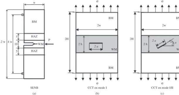
In this paper, two-dimensional plane strain, finite element analyses using the J-integral method are conducted for modelling the crack growth in a mis-matched specimen, Figure 1. A crack is assumed to be located in the center line of the weld. Moreover, the interfaces between the weld metal and the base metal are assumed to be perfectly bonded, so that debonding along the interface can not occur. It is assumed that crack growth occurs along the center line of the weld. Throughout this paper, attention is concentrated on such idealized bi-material weld with a mismatch in strength, so that the yield strength of the weld metal (σyWF), differs from the base metal yield strength (σyBM). The difference in the strength level is quantified by the mis-match ratio
yWF
y BM
M = σ
σ (2)
With M > 1 referring to as overmatching, M < 1 as undermatching and M = 1 as matching.
3. Geometrical and Materials Models
A number of typical crack specimens with unit thickness are adopted in our numerical tests. They include:
• TPCB(SENB):thethree-pointcrackedbeambending
specimen with concentrated load P, Figure 1a;
• CCP1:thecentercrackedpanelunderoverturemode
loading (mode I), Figure 1b; and
• CCP2:thecentercrackedpanelundermixedmode
loading (mode I/II), Figure 1c.
All behaviours of the materials used in this study were assumed to follow a Ramberg–Osgood law:
e n
e E
K
e p
e
p
pour pour
ε = ε + ε
σ = ε σ ≤ σ
σ = ε σ > σ
(3)
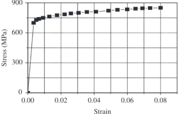
The typical uniaxial stress-strain curve of this material at room temperature is given in Figure 2. Full details of the behaviour law of this steel are given elsewhere26.
4. Finite Element Modelling
Fracture mechanics aims to determine the effect of any cracks on the structures mechanical behaviour. The problems of cracked of the welded joint are more complicated than the cracked problems of the homogenous materials. Because, the stress field at the tip of the crack greatly depend on the mechanical behaviour of materials. Computational methods such as finite element method are widely accepted in pipe
lines27 and a welded joint28 as an important tool used to
investigate the fracture of these structures. Contributing to this field, we analysed the fracture behaviour of welded joint by the computation of J-integral at the crack front. Finite element simulation was done using Cast3M code29
(elastic-plastic fracture mechanics). Figure 3 shows the finite element mesh. Taken into account the symmetry of loading and geometry, only the half of the model is studied in order to reduce the calculation time. Quadratic elements are used in the modelling. The singularity at the near of the crack is modelled by special elements in order to increase the precision of calculation. The theory of incremental plasticity is introduced to model the material nonlinearity. The iterative method of Newton-Raphson is used as an approach to solve nonlinear equations by finite elements.
5. Results and Discussions
5.1.
Validation of the finite element analysis (case
of SENB specimen)
The crack behaviour is analysed by computing the J-integral at the crack front of welded joint. For the first step, it is necessary to validate the J-integral results for SENB specimen. A number of finite element analyses (FEA) was performed initially for one case taken from the past work of Rodrigues27. Figure 4 show the variation of the J-integral
versus imposed displacement for the geometrical crack configurations conducted for this study. We can observe from Figure 4 that the J-integral increases proportionally with the increasing of the imposed displacement (applied load). However, in this configuration of crack size of welded joint it was found that under lower applied load (imposed displacement < 0.2 mm), the J-integral increases significantly with the increasing of the applied load, while
Figure 2. Uniaxial stress–strain curve of the steel at room
temperature24.
under higher applied load (imposed displacement > 0.2 mm), the J-integral increases sharply with respect to the crack size. Figure 4 shows also, the comparisons of J-integral versus imposed displacement plots from the present study with the corresponding finite element results generated by Rodrigues26.
The results are in good agreement with each other.
To study the effect of loading on the behaviour fracture of the welded joint, we have plotted the curve in Figure 5 which illustrates the evolution of J-integral versus the loading; these results show that the rate of increase of the J-integral is more important when the loading exceeds 300 MPa. This phenomena can be attributed for the value of applied load under which the plastic strain is absent for the loading values lower at limit load (elastic region). The stress level around the crack is lower than the yield strength of material used in the present work. We have noted, however, that for higher loading (P > 300 MPa) the level of stresses near the crack tip is higher than the yield strength which cause plastic strains (plastic region), with the magnitude of plastic strain governing the evolution of J-integral. Beyond the limit load, the increasing rate of J-integral has an exponential form versus loading. These results are in good agreement with those found in the literature11,14,15,30-32.
5.2.
Central Crack in Tension CCT
In this case, the study focuses on a CCT configuration (Figure 1). We have examined the opening mode (mode I) and the mixed mode (mode I/II) to evaluate the J-integral for the study of a welded joint formed by the weld metal and the base metal. We present in this section a numerical calculation based on the J-integral concept for the study of a welded joint. The material law behaviour used is a power law, Equation 6. Table 1 Recall the mechanical properties of the material (WM and BM) considered for this joint. The loading is simulated by imposing an incremental displacement with a step of 0.1 mm.
5.2.1. Opening mode (mode I)
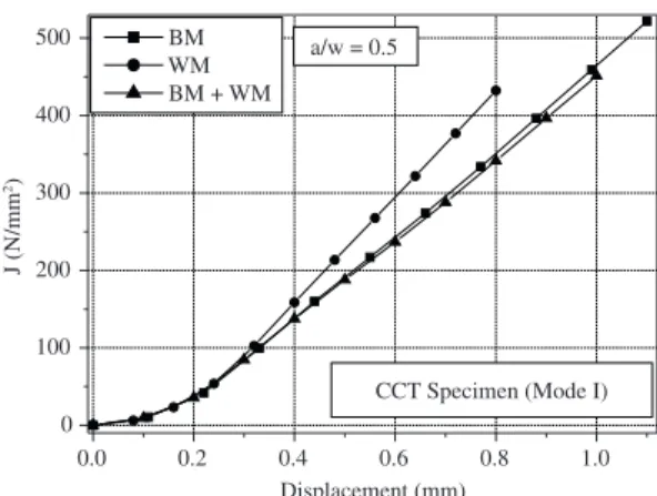
The two-dimensional numerical study was performed with three configurations (BM, WM and BM + WM). In Figure 6 we represent the evolution of the J-integral over the imposed displacement. From the results shown in Figure 6, we can deduce that the evolution of the J-integral is plotted for a displacement reached a value of 1.1 mm for the base metal (BM), 0.8 mm for the weld metal (WM) and 1.0 mm for the (WM + BM) case.
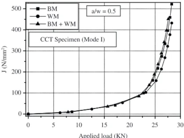
These results clearly show that when the properties of material ductility are higher, the evolution of the J-integral versus load (imposed displacement) is higher. This is explained by the fact that the extension of a ductile material (case of BM) is higher than that of a brittle material (case of WM) because of the effect of the heat of the welding process. We can also determine the evolution of the J-integral as a function of loading (Figure 7). We note first that the evolution of the J-integral versus load is almost similar to that shown in Figure 5 (case of the SENB specimen). This
Figure 4. Curve J-Displacement for (a/w = 0.5)
Figure 5. Curve J-Applied load for (a/w = 0.5)
Figure 6. Curve J-Displacement for (a/w = 0.5)
Table 1. Parameter values of the power law describing the materials
considered (BM, WM)22.
Materials
Mechanical properties
Re
(N.mm–2)
Rm
(N.mm–2) K n
BM 325 400 980 0.401
behaviour was confirmed analytically and numerically by other authors7,9,19-20.
5.2.2. Mixed mode (Mode I/II)
In this section we have discussed the influence of failure mode on the evolution of the J-integral for the study of a welded joint. Figures 8 and 9 show the effect of failure mode (angle variation) on the evolution of the J-integral versus imposed displacement and loading respectively for the three configurations studied (BM, WM and BM + WM). We note that whatever the material studied, the angle variation effect is negligible for low load values and the opposite effect is observed for high load values.
However, we note that the failure mode effect (angle variation) can be ignored in the elastic regime (i.e. the stress level near the crack is lower). For the elastic plastic regime,
Figure 7. Curve J-Applied load for (a/w = 0.5)
• Whateverthemodeoffailure,theJ-integralisstrongly
influenced by the material properties;
• Thefailuremodeeffectcanbeignoredintheelastic
regime and the opposite effect is marked for the elastic plastic regime. We can conclude that the parameters of ductility of a material (hardening curve) play an important role for studying the fracture behaviour of a weld;
• Accordingtotheiniteelementresults,theJ-integral
values are identified for pure mode (mode I) and mixed mode (mode I/II) (case of variation of the crack orientation); and
• The J-integral can be signiicantly affected by the
mismatch factors on material hardening parameters, and law behavior parameters for weld and base metal should be accounted for when calculating J-integral. the crack angle inclination has a predominant effect on the
J-integral evolution to study the welded joint behaviour (i.e. stress level near the crack is higher).
6. Conclusion
In this numerical study, the results have highlighted the following points:
• The transition from a homogeneous coniguration
(WM or BM) to a heterogeneous configuration (WM + BM) has a significant influence on the evolution of the J-integral versus the load;
• Fortheopenmode(modeI),theJ-integralvaluesare
higher than those for the mixed mode (mode I/II);
• Thecrackdirection(anglevariation)hasapredominant
effect on the J-integral for the study of a welded joint;
References
1. Meric C and Tokdemir M. An Investigation of the Weld Region of the SAE 1020 Joined with Metal Active Gas and Determination of the Mismatch Factor. ASM International. Journal of Materials Engineering and Performance. 1999; 8:601-605. http://dx.doi.org/10.1007/s11665-999-0016-4
2. Bose Filho WW, Carvalho ALM and Bowen P. Micromechanisms of cleavage fracture initiation from inclusions in ferritic welds. Part II. Quantification of local fracture behaviour observed in fatigue pre-cracked test pieces. Materials Science and Engineering A. 2007; 452-453:401-410. http://dx.doi. org/10.1016/j.msea.2006.10.096
3. Biswas K. Notch tip deformation and J-integral analysis for implant weldability test specimen. International Journal of Fracture. 1994; 67:99-116. http://dx.doi.org/10.1007/ BF00019597
4. Mersida M, Bojan M, Ljubica M, Marko R, Zijah B and Aleksandar S. Analysis of welded tensile plates with a surface notch in the weld metal and heat affected zone. Engineering Fracture Mechanics. 2010; 77:2958-2970. http://dx.doi. org/10.1016/j.engfracmech.2010.03.042
5. Lee H and Cho J. Overload analysis and fatigue life prediction of spot-welded specimens using an effective J-integral. Mechanics of Materials. 2005, 37(1):19-32. http://dx.doi. org/10.1016/j.mechmat.2003.12.006
6. Hyungyil L and Yun-Jae K. Interfacial crack-tip constraints and J-integral for bi-materials with plastic hardening mismatch. International Journal of Fracture. 2007; 143:231-243. http:// dx.doi.org/10.1007/s10704-006-9025-6
7. Jianqing F and Yaowu S. Mechanical heterogeneity and validity of J-dominance in welded Joints. International Journal of Fracture. 2000; 106:311-320. http://dx.doi. org/10.1023/A:1026501828215
8. Boothman DP, Lee MMK and Luxmoore AR. The effects of weld mismatch on J-integrals and Q-values for semi-elliptical surface flaws. Engineering Fracture Mechanics. 1999; 64:433-458. http://dx.doi.org/10.1016/S0013-7944(99)00091-0
9. Burstow MC, Howard IC and Ainsworth RA. The effect of material strength mismatching on constraint at the limit load of welded three-point-bend specimens. International Journal of Fracture. 1998; 89:117-142. http://dx.doi. org/10.1023/A:1007480827982
10. ShamTL, Li J and Hancoc KJW. A family of plane strain crack tip stress fields for interface cracks in strength mismatched
elastic-perfectly plastic solids. Journal of the Mechanics and Physics of Solids. 1999; 47:1963-2010. http://dx.doi. org/10.1016/S0022-5096(99)00004-6
11. Lee H and Kim YJ. Interfacial crack-tip constraints and J-integrals in plastically mismatched bi-materials. Engineering Fracture Mechanics. 2001; 68:1013-1031. http://dx.doi. org/10.1016/S0013-7944(01)00007-8
12. Heuser A, Twickler R and Dahl W. Experimental investigations of the failure behaviour of welded joints and its numerical simulation by using elastic-plastic finite element calculation. The Fracture Mechanics of welds, Mechanical Engineering publications. 1987; 97-124.
13. Lei Y, Ainsworth RA. A J-integral estimation method for cracks in welds with mismatched mechanical properties. International Journal of Pressure Vessels and Piping. 1997; 70:237-245. http://dx.doi.org/10.1016/S0308-0161(96)00035-X
14. Lei Y and Ainsworth RA. The estimation of J in three-point-bend specimens with a crack in a mismatched weld. International Journal of Pressure Vessels and Piping. 1997; 70:247-257. http://dx.doi.org/10.1016/S0308-0161(96)00036-1
15. Mark F and Sharif R. Probabilistic analysis of weld cracks in center-cracked tension specimens. Computers and Structures. 2000; 76:483-506. http://dx.doi.org/10.1016/ S0045-7949(99)00127-3
16. Kamat SV and Hirth JP. Mixed mode I/II fracture toughness of 2034 aluminum alloys. Acta Materialia. 1996; 44:201-208. http://dx.doi.org/10.1016/1359-6454(95)00169-8
17. Sutton MA, Boone ML, Ma F and Helm JD. A combined modeling-experimental study of the crack opening displacement fracture criterion for characterization of stable crack growth under mixed mode I/II loading in thin sheet materials. Engineering Fracture Mechanics. 2000; 66:171-185. http:// dx.doi.org/10.1016/S0013-7944(00)00011-4
18. Pirondi A and Nicoletto G. Mixed mode I/II fracture toughness of bonded joints. International Journal of Adhesion and Adhesives. 2002; 22:109-117. http://dx.doi.org/10.1016/S0143-7496(01)00042-2
19. Anderson TL. Fracture mechanics fundamentals and applications. CRC Press; 1995.
27. Yueli L, Lixing H, Yufeng Z and Xinqi Y. Effect of mismatching on J-integral for pipe-welded joints with circumferential through-wall crack. International Journal of Pressure Vessels and Piping. 1999; 76:857-862. http://dx.doi.org/10.1016/ S0308-0161(99)00056-3
28. Paolo L and Roberto T. The use of the JV parameter in welded joints: Stress analysis and fatigue assessment. International Journal of Fatigue. 2009; 31:153-163. http:// dx.doi.org/10.1016/j.ijfatigue.2008.06.007
29. Cast3M. Available from: <www-cast3m.cea.fr>.
30. Lei YP, Shi YW, Murakawa H and Luo Y. The effect of mechanical heterogeneity and limit load of a weld joint with longitudinal weld crack on the J-integral and failure assessment curve. International Journal of Pressure Vessels and Piping. 1998; 75:625-632. http://dx.doi.org/10.1016/ S0308-0161(98)00067-2
31. Rahman S and Brust FW. Elastic-plastic analysis of weld cracks in tubular structures, pipeline special investigation report. Washington: National Transportation Safety Board.
32. Bouchouicha B. Contribution à l’étude de la déchirure ductile et de la propagation des fissures en fatigue dans les joints soudés. [Thesis]. Sidi Bel Abbes: Djillali Liabes University; 2007.
21. British Standards Institution - BSI. Guide on methods for assessing the acceptability of flaws in structures. BSI; 1999. Guide B57910.
22. R6 - Assessment of the integrity of structures containing defects. 3rd rev. British Energy Generation Ltd; 1999.
23. Casavola C, Pappalettere C and Tattoli F. Experimental and numerical study of static and fatigue properties of titanium alloy welded joints. Mechanics of Materials. 2009, 41:231-243. http://dx.doi.org/10.1016/j.mechmat.2008.10.015
24. Jiang WC, Wang BY, Gong JM and Tu ST. Finite element analysis of the effect of welding heat input and layer number on residual stress in repair welds for a stainless steel clad plate. Materials & Design. 2011; 32:2851-2857. http://dx.doi. org/10.1016/j.matdes.2010.12.037
25. Panda SK and Kumar DR. Experimental and numerical studies on the forming behavior of tailor welded steel sheets in biaxial stretch forming. Materials & Design. 2010; 31:1365-1383. http://dx.doi.org/10.1016/j.matdes.2009.08.046