UNIVERSIDADE DA BEIRA INTERIOR
Engenharias
Sustainable Distribution Network Planning
Considering Multi-Energy Systems and Plug-In
Electric Vehicles Parking Lots
Nilufar Neyestani
Tese para obtenção do Grau de Doutor em
Engenharia e Gestão Industrial
(3º ciclo de estudos)
Orientador: Prof. Doutor João Paulo da Silva Catalão
Coorientador: Prof. Doutor João Carlos de Oliveira Matias
UNIVERSIDADE DA BEIRA INTERIOR
Engenharias
Sustainable Distribution Network Planning
Considering Multi-Energy Systems and Plug-In
Electric Vehicles Parking Lots
Nilufar Neyestani
Thesis submitted in fulfillment of the requirements for the degree of
Doctor of Philosophy in
Industrial Engineering and Management
(3
rdcycle of studies)
Supervisor: Prof. Doutor João Paulo da Silva Catalão
Co-supervisor: Prof. Doutor João Carlos de Oliveira Matias
This work was supported by FEDER funds (European Union) through COMPETE and
by Portuguese funds through FCT, under Projects FCOMP-01-0124-FEDER-020282
(Ref. PTDC/EEAEEL/118519/2010) and UID/CEC/50021/2013. Also, the research
leading to these results has received funding from the EU 7th Framework Programme
FP7/2007-2013 under grant agreement no. 309048.
Acknowledgment
Firstly, I would like to express my sincere gratitude to my PhD. advisor Prof. João Paulo da Silva Catalão for the continuous support of my PhD study and related research, for his motivation, and encouragement during these past two years.
Besides my advisor, I would like to thank Prof. Gianfranco Chicco (Politecnico di Torino) for his trust and support. I am grateful for the opportunity he gave me to stay as the visiting student in Torino and all his help and insightful comments throughout my studies. My sincere thanks also go to Prof. Javier Contreras (University of Castilla- La Mancha) and Prof. Anastasios G. Bakirtzis (Aristotle University of Thessaloniki) for giving me the honor of collaborating with them in my research in several papers.
I thank all the co-authors of my works and especially to my closest collaborators, Dr. Maziar Yazdani and Dr. Miadreza Shafie-khah. I thank my fellow labmates in “Sustainable Energy Systems Lab” for the stimulating discussions, for the sleepless nights we were working together before deadlines, and for all their help in the past years.
As regards the development and improvement of the technical content of the work that is included in this thesis, the "anonymous" Reviewers of several journals have played an important role with their insights into my manuscripts.
Last but not least, I would like to thank my family: my parents and my brother, and all my friends who have been beside me in the last three years, for supporting me spiritually throughout writing this thesis and my life in general.
iii
Resumo
Entre todos os recursos associados à evolução das redes elétricas para o conceito de smart grid, os sistemas de multi-energia e os veículos eléctricos do tipo plug-in (PEV) são dois dos principais tópicos de investigação hoje em dia. Embora estes recursos possam acarretar uma maior incerteza para o sistema de energia, as suas capacidades de demanda/armazenamento flexível de energia podem melhorar a operacionalidade do sistema como um todo. Quando o conceito de sistemas de multi-energia e os parques de estacionamento com estações de carregamento para os PEVs são combinados no sistema de distribuição, a demanda pode variar significativamente. Sendo a demanda de energia uma importante informação no processo de planeamento, é essencial estimar de precisa essa demanda. Deste modo, três níveis padrão de carga podem ser extraídos tendo em conta a substituição da procura entre carriers de energia, a demanda associada ao carregamento dos PEVs, e presença de parques de estacionamento com estações de carregamento no sistema. A presença de PEVs num sistema multi-energia obriga a outros requisitos (por exemplo, um sistema de alimentação) que devem ser fornecidos pelo sistema, incluindo as estações de carregamento.
A componente elétrica dos PEVs dificulta a tarefa ao operador do sistema na tentativa de encontrar a melhor solução para fornecer os serviços necessários e utilizar o potencial dos PEVs num sistema multi-energia. Contudo, o comportamento sociotécnico dos utilizadores de PEVs torna difícil ao operador do sistema a potencial gestão das fontes de energia associada às baterias. Desta forma, este estudo visa providenciar uma solução para os novos problemas que irão ocorrer no planeamento do sistema. Nesta tese, vários aspetos da integração de PEVs num sistema multi-energia são estudados. Primeiro, um programa de resposta à demanda é proposto para o sistema multi-energia com tecnologias do lado da procura que possibilitem alternar entre fornecedores de serviços. Em seguida, é realizado um estudo abrangente sobre as questões relativas à modelação dos PEVs no sistema, incluindo a modelação das incertezas, as preferências dos proprietários dos veículos, o nível de carregamento dos PEV e a sua interação com a rede. Posteriormente é proposta a melhor estratégia para a participação no mercado de energia e reserva. A alocação na rede e os possíveis efeitos subjacentes são também estudados nesta tese, incluindo o modelo dos PEVs e dos parques de estacionamento com estações de carregamento nesse sistema de multi-energia.
Palavras-chave
Estações de carregamento, carga flexível, sistemas de multi-energia, demanda multi-energia, programação matemática com restrições de equilíbrio, programação linear inteira mista, planeamento da rede, parques de estacionamento, veículos elétricos
Abstract
Among all resources introduced by the evolution of smart grid, multi-energy systems and plug-in electric vehicles are the two maplug-in challenges plug-in research topics. Although, these resources bring new levels of uncertainties to the system, their capabilities as flexible demand or stochastic generation can enhance the operability of system. When the concept of multi-energy systems and plug-in electric vehicles (PEV) parking lots are merged in a distribution system, the demand estimation may vary significantly. As the main feed of planning process, it is critical to estimate the most accurate amount of required demand. Therefore, three stages of load pattern should be extracted taking into account the demand substitution between energy carriers, demand affected by home-charging PEVs, and parking lot presence in system. The presence of PEVs in a multi-energy system oblige other requirements (i.e. fueling system) that should be provided in the system, including charging stations. However, the electric base of PEVs adds to the responsibilities of the system operator to think about the best solution to provide the required services for PEVs and utilize their potentials in a multi-energy concept. However, the socio-technical behavior of PEV users makes it difficult for the system operator to be able to manage the potential sources of PEV batteries. As a result, this study tries to raise the solution to new problems that will occur for the system planners and operators by the future components of the system.
In this thesis, various aspects of integrating PEVs in a multi-energy system is studied.Firstly, a carrier-based demand response program is proposed for the multi-energy system with the technologies on the demand side to switch between the carriers for providing their services. Then, a comprehensive study on the issues regarding the modeling of the PEVs in the system are conducted including modeling their uncertain traffic behavior, modeling the preferences of vehicle owners on the required charging, modeling the PEV parking lot behavior and its interactions with the network. After that the best strategy and framework for participating the PEVs energy in the energy and reserve market is proposed. The allocation of the parking lot in the network and the possible effects it will have on the network constraints is studied. Finally, the derived model of the PEVs and the parking lot is added to the multi-energy system model with multi-energy demand.
Keywords
Charging stations, flexible load, multi-energy systems,multi-energy demand, mathematical programming with equilibrium constraints, mixed integer linear programming, network planning, parking lots, plug-in electric vehicles.
Contents
1 Introduction 1
1.1 Background and Motivation . . . 1
1.2 Research Questions and Contribution of the Thesis . . . 3
1.3 Outline of the Thesis . . . 4
2 Literature Review 6 2.1 PEVs State Description in Energy Systems . . . 6
2.2 Potential PEV Modes in the system . . . 6
2.2.1 Uncontrolled/Controlled Charging mode . . . 7
2.2.2 V2G mode . . . 8
2.3 Aggregated Operation of PEVs in the Electric System . . . 9
2.3.1 Charging Scheduling of PEV Aggregator . . . 9
2.3.2 Market Participation of PEV Aggregator . . . 10
2.3.3 Network Impacts and Planning Concerns of PEV Aggregator . . . 11
2.4 The PL as a New Mode of PEV Aggregation . . . 12
2.5 Integration of PEVs in the MES concept . . . 13
3 Modeling the Demand Dependency in Multi-Energy Systems 16 3.1 Introduction . . . 16
3.2 Carrier-Based Demand Response Concept Description . . . 16
3.3 Internal and External dependencies . . . 18
3.4 Comprehensive Energy System Model . . . 20
3.4.1 Energy Converter Model . . . 21
3.4.2 Energy Storage Model . . . 22
3.5 Local Energy System Stochastic Operational Model . . . 23
3.5.1 Objective Function . . . 24
3.5.2 Operational Constraints . . . 25
3.5.3 Model of External Dependency . . . 26
3.6 Uncertainty Characterization of Internal and External Dependency . . . 27
3.6.1 Uncertainty of Carrier-Based Demand Response . . . 28
3.6.2 Modeling the Uncertainties of CBDR and Carrier Share . . . 29
3.7 Case Studies . . . 29
3.7.1 Case I: The Operational Model Study . . . 31
3.7.2 Case II: Comparison of Stochastic and Deterministic Results . . . 34
3.8 Chapter Summary . . . 38
4 Deriving the PEVs Traffic Pattern Model based on the Socio-Technical Prefer-ences 40 4.1 Introduction . . . 40
4.2 Stochastic Modeling of PEVs’ Parking Lot . . . 40
4.3 PEV Characterization . . . 42
4.3.1 PEV Behavior . . . 43
4.3.2 Scenario Generation for PEV Behavior in PL . . . 43
4.3.3 Determination of PEV Preference Parameters . . . 44
4.4.1 Traffic Flow Constraints . . . 49
4.4.2 Zone Constraints . . . 49
4.4.3 Urban Constraints . . . 51
4.4.4 PL Constraints . . . 52
4.5 Chapter Summary . . . 53
5 Modeling the PL’s Operational Behavior and Market Participation 54 5.1 Introduction . . . 54
5.2 Problem Description . . . 54
5.2.1 Aggregator-PL-PEV interactions . . . 55
5.2.2 Aggregator - DG Interaction . . . 56
5.2.3 Aggregator – Demand Interaction . . . 56
5.3 Approach for solving the problem . . . 57
5.4 Upper Level Mathematical Model . . . 58
5.5 Lower Level Mathematical Model . . . 60
5.5.1 PL-Aggregator Interaction . . . 60
5.5.2 DG-Agg Interactions . . . 64
5.5.3 Demand-Agg Interactions . . . 64
5.6 MPEC Formulation and Strong Duality . . . 65
5.7 Case Studies . . . 66
5.7.1 Case I: Pay as Bid . . . 66
5.7.2 Case II: Uniform Pricing . . . 69
5.8 The role of PEV preferences on Aggregator Equilibrium . . . 73
5.9 Chapter Summary . . . 75
6 Allocation of the PL in a Renewable-based Distribution Network 77 6.1 Introduction . . . 77
6.2 Problem Overview . . . 77
6.2.1 Procedure and Assumptions . . . 78
6.2.2 Uncertainty Characterization . . . 79
6.3 First Stage: PL Model . . . 82
6.3.1 Objective Function . . . 82
6.3.2 Constraints . . . 83
6.4 Second Stage: Allocation of PEV’s Parking Lots . . . 86
6.4.1 Installation Costs . . . 87
6.4.2 Loss Costs . . . 88
6.4.3 Voltage Deviation Costs . . . 89
6.4.4 Network Reliability Costs . . . 90
6.5 Case Studies . . . 91
6.5.1 PL Behavior Results . . . 91
6.5.2 PL Allocation . . . 93
6.6 Chapter Summary . . . 98
7 Integration of the PEVs PL in the multi-energy system modeling 100 7.1 Introduction . . . 100
7.2 Problem Description . . . 100
7.3 Matrix modeling of MES with PL and HC . . . 102
7.3.2 HC model in MED . . . 105
7.4 Case-Studies . . . 106
7.4.1 Case I: micro MES with PL and no HC . . . 107
7.4.2 Case II: micro MES with HC on MED and no PL . . . 107
7.4.3 Case III: micro MES with PL and HC . . . 108
7.4.4 Case IV: Mutual effect of two micro MESs with PL and HC . . . 109
7.5 Chapter Summary . . . 112
8 Conclusions 114 8.1 Main Conclusions . . . 114
8.2 Outlook for the Future Works . . . 118
8.3 List of Publications . . . 118
Bibliografia 121 A Mathematical Formulation for solving the bilevel problem with MPEC 132 A.1 Lagrangian Equation . . . 132
A.2 Stationary Conditions . . . 132
A.3 Complementary Conditions . . . 135
A.4 Strong Duality . . . 136
List of Figures
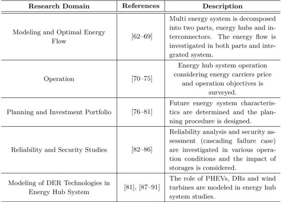
3.1 Structure of DER supply and related dependencies in serving multi-energy demand 19
3.2 Energy system comprehensive module considering internal and external dependencies. 20
3.3 A typical local energy network model considering the energy carriers dependency. . 23
3.4 Share of demand participation variables in dependent demand. . . 27
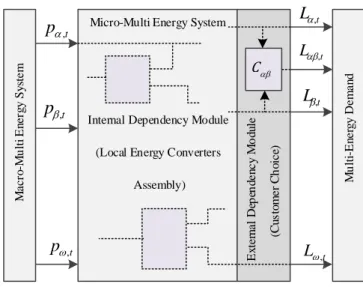
3.5 Energy carriers demand data in the operation time horizon. . . 30
3.6 Energy carriers price data in the operation time horizon. . . 31
3.7 Heat demand data in the operation time horizon. . . 31
3.8 System operation cost based on demand dependency percentage for different water heater efficiencies. . . 32
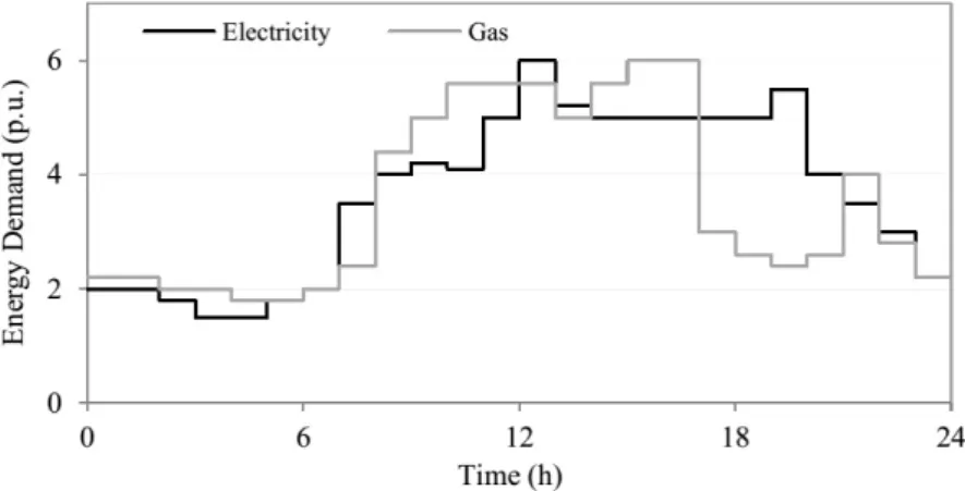
3.9 Evolution of the electricity input for demand dependency percentage from 0 to 100%, with ηdd g = 0.6. Internal zoom for hour 7 A.M.. . . . 33
3.10 Evolution of the gas input for demand dependency percentage from 0 to 100%, with ηdd g = 0.6. Internal zoom for hour 7 A.M.. . . . 33
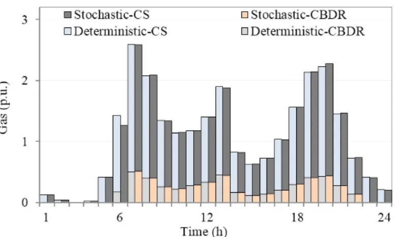
3.11 Contribution of CBDR and CS to the electricity share of dependent demand for deterministic and stochastic models. . . 34
3.12 Contribution of CBDR and CS to the electricity share of dependent demand for deterministic and stochastic models. . . 35
3.13 Electricity input variation for various stochastic scenarios. . . 36
3.14 Gas input variation for various stochastic scenarios. . . 36
3.15 Variance of input power and gas. . . 37
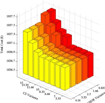
3.16 Variation of total cost vs. variation in CBDR and CS variance. . . 38
3.17 Stored heat variation in heat storage for deterministic and stochastic models. . . . 38
4.1 Distribution of battery capacity. . . 41
4.2 The hourly nominal capacity of parking lot. . . 41
4.3 The hourly SOC of parking lot. . . 42
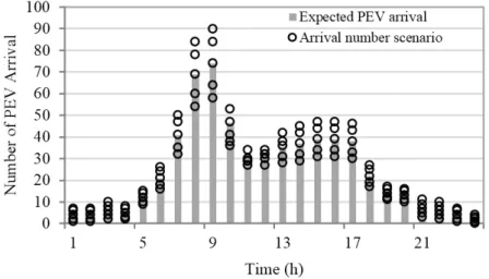
4.4 Expected value of PEV arrival to PL and its scenarios. . . 43
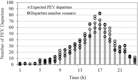
4.5 Expected value of PEV departure from the PL and its scenarios. . . 44
4.6 Expected value of PEVs’ number in the PL and its scenarios. . . 44
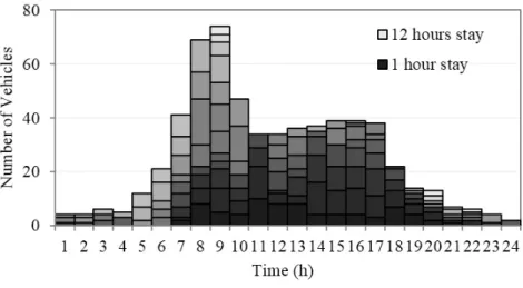
4.7 Total number of PEVs in the PL in each hour based on their expected stay duration. 45 4.8 Classification of PEVs based on their stay duration. . . 45
4.9 Flowchart of generating scenario for PEVs’ number in PL. . . 46
4.10 The interaction of PEV numbers between environment and zone and inside the zone. 48 4.11 The amount of power exchanged between environment and zone (PL and urban area). 49 5.1 Interactions of the components in the environment. . . 55
5.2 The sequence of interactions from PEVs to Market . . . 56
5.3 Energy prices for aggregator, PL, and DG in Case I. . . 67
5.4 Energy balance of system in Case I. . . 67
5.5 PL’s power exchange in Case I. . . 68
5.6 Upstream reserve market and LL reserve equilibrium prices in Case I. . . 68
5.7 PL’s state of charge for various categories of PEVs in PL in Case I. . . 69
5.8 Energy Market and Energy Equilibrium prices in Case II. . . 70
5.10 Reserve Market and Reserve Equilibrium prices in Case II. . . 71
5.11 PL’s power exchange in Case II. . . 72
5.12 The behavior of PL in charging Flex2 contracts in Case II. . . 72
5.13 Comparison of PL’s capacity and SOC divided by G2V and V2G PEVs in Case II. 73 5.14 Aggregator profit in Case II for various G2V2 and G2V3 prices. . . 74
5.15 PL profit in Case II for various G2V2 and G2V3 prices. . . 74
5.16 Equilibrium energy price for various G2V3. . . 75
5.17 Equilibrium reserve price for various G2V3. . . 75
5.18 Equilibrium reserve price for various G2V2. . . 76
6.1 Flowchart of the overall algorithm. . . 80
6.2 Capacity and SOC scenarios of PEVs. . . 81
6.3 Output generation of RERs. . . 82
6.4 Average price of energy and reserve. . . 82
6.5 PL behavior, capacity, and state of charge in case 1. . . 92
6.6 PL behavior, capacity, and state of charge in case 2. . . 92
6.7 Comparison of PL input power in cases 1 and 2. . . 93
6.8 Comparison of PL output power in cases 1 and 2. . . 93
6.9 PL profit comparison in the two cases. . . 94
6.10 PL distribution in the network with a loss cost function: (a) 50 stations; (b) 100 stations; (c) 150 stations; (d) 200 stations; (e) 250 stations. . . 95
6.11 PL allocation with a reliability cost function: (a) 50 stations; (b) 100 stations; (c) 150 stations; (d) 200 stations; (e) 250 stations. . . 96
6.12 EENS for various numbers of PL stations. . . 97
6.13 DSO cost for EENS only. . . 97
6.14 Total system cost for reliability improvement. . . 98
6.15 PL allocation with a voltage deviation cost function: (a) 50 stations; (b) 100 stations; (c) 150 stations; (d) 200 stations; (e) 250 stations. . . 98
6.16 PL allocation with a total cost function. . . 99
7.1 The integration of PEV traffic in PL and ChS with MES model. . . 102
7.2 Schematic of micro MES with PL and HC. . . 102
7.3 Electricity balance in micro MES components in case I. . . 107
7.4 Electricity balance in micro MES components in case II. . . 108
7.5 Electricity balance in micro MES components in case III. . . 109
7.6 The integration of PEV traffic in PL and ChS with MES model. . . 110
7.7 Electricity balance for micro-MES # 1 in Case I. . . 110
7.8 Electricity balance for micro-MES # 2 in Case I. . . 111
7.9 Electricity balance for micro-MES # 1 in Case II. . . 111
7.10 Electricity balance for micro-MES # 2 in Case II. . . 112
7.11 Heat balance comparison between two micro-MESs in two Cases: (a) and (c) heat balance in Case I in micro-MES 1 and 2, respectively; (b) and (d) heat balance in Case II in micro-MES 1 and 2, respectively. . . 112
List of Tables
2.1 Research Domains in Energy Hub System Studies . . . 14
3.1 Data of Local Energy Network Elements. . . 30
3.2 Data on Dependency Scenarios . . . 34
4.1 Values of ϕ for different PEV categories . . . . 45
4.2 Values of β for different PEV categories . . . . 47
4.3 Values of θ for different PEV categories . . . . 47
5.1 PEV Owners Clustering . . . 61
6.1 Results for each Objective Function . . . 97
List of Acronyms
AB Auxiliary boiler
Agg Aggregator
BEV Battery-exchange Electric Vehicles
CBDR Carrier-Based Demand Response
CHP Combined Heat and Power
ChS Charging Stations for PEVs
CS Carrier Share
DER Distributed Energy Resource
DG Distributed Generation
DMG Distributed Multi-energy Generation
DR Demand Response
DSO Distribution System Operator
ED External Dependency
EENS Expected Energy Not Served
EEq Energy Equilibrium point
EM Electricity Market
EV Electric Vehicle
FOR Forced Outage Rate
G2V Grid to Vehicle HC Home-Charging vehicles HS Heat Storage IL Interruptible Load KKT Karush-Kuhn-Tucker LL Lower Level
MED Multi Energy Demand
MES Multi Energy System
MPEC Mathematical Programming with Equilibrium Constraints
MILP Mixed Integer Linear Programming
PDF Probability density function
PEV Plug-in Electric Vehicle
PHEV Plug-in Hybrid Electric Vehicle
PL Parking Lot
PV Photo Voltaic
RER Renewable Energy Resources
REq Reserve Equilibrium point
RM Reserve Market
RWM Roulette Wheel Mechanism
SOC State of Charge
TM Trade with Market
TPL Trade with PL
TDG Trade with DG
TDemand Trade with Demand
UL Upper Level
Nomenclature
The main notations used in this thesis is presented below separately for each chapter. It should be noted that some of the notations are used in different chapters; however, for the sake of consistency they are repeated in each chapter that they are being used.
Chapter 3
Sets and Indices
a, b, z Index (set) of generic energy carriers.
e Index of electric energy carrier.
DO Index of dependent output.
g Index of gas energy carrier.
h Index of heat energy carrier.
IO Index of independent output.
t Index (set) of Time interval.
ω Index (set) of uncertainty scenarios.
Parameters
Gω,t Maximum gas input to micro-MES.
HAB Maximum heat output of AB unit.
HAB Minimum heat output of AB unit.
HCHP Maximum heat output of CHP unit.
HCHP Minimum heat output of CHP unit.
HHS Maximum heat output of HS unit.
HHS Minimum heat output of HS unit.
Le,t Electric demand.
Lg,t Gas demand.
Lh,t Heat demand.
Leg,t Total dependent demand between gas and electricity energy carriers.
Wω,t Maximum electricity input to micro-MES
WCHP Maximum electricity output of CHP unit.
WCHP Minimum electricity output of CHP unit.
ΓHS Charge/discharge rate of HS.
ηeCHP Efficiency of CHP unit in producing electricity.
ηhCHP Efficiency of CHP unit in producing heat.
ηAB
h Efficiency of AB in producing heat.
ηHS
h Efficiency of HS in providing heat.
Πe,t Price of electricity energy carrier.
ΨCHP Maximum heat to power of CHP unit.
ΨCHP Minimum heat to power of CHP unit.
Variables
ginω,t Hourly gas energy carrier input to the micro-MES in different scenarios.
hCHPω,t Hourly heat produced by the CHP unit in different scenarios.
hHSω,t Hourly heat produced by the HS unit in different scenarios.
˙hHS
ω,t The difference in heat stored in the HS in two consecutive time intervals for each
scenario.
leg,ω,tCB The hourly amount of DD that will participate in CBDR program in each scenario.
lCB
e,ω,t The hourly amount of electricity from total DD that will participate in CBDR program in each scenario.
lCB
g,ω,t The hourly amount of gas from total DD that will participate in CBDR program in each scenario.
le,ω,tCS The hourly amount of electricity from total DD that will behave based on CS in each scenario.
lCS
g,ω,t The hourly amount of gas from total DD that will will behave based on CS in each scenario.
vAB
g,ω,t Decision variable for determining the share of AB unit in consumption of total input gas in different scenarios.
vω,tCB Decision variable for determining the hourly share of CBDR program from total
DD in different scenarios.
vCHP
g,ω,t Decision variable for determining the share of CHP unit in consumption of total input gas in different scenarios.
vCS
e,ω,t Decision variable for determining the share of DD that will behave based on CS and choose to use electricity in each scenario.
vg,ω,tCS Decision variable for determining the share of DD that will behave based on CS and choose to use gas in each scenario.
vdd
e,ω,t Decision variable for determining the hourly share of electricity of DD from total input electricity in different scenarios.
vdd
g,ω,t Decision variable for determining the hourly share of gas of DD from total input electricity in different scenarios.
ve,ω,tout Decision variable for determining the hourly electricity output of micro-MES from total input electricity in different scenarios.
vout
g,ω,t Decision variable for determining the hourly gas output of micro-MES from total input gas in different scenarios.
win
ω,t Hourly electricity energy carrier input to the micro-MES in different scenarios.
wCHP
ω,t Hourly electricity produced by the CHP unit in different scenarios.
ψCHP
Chapter 4
Sets and Indices
i, j Indices (sets) indicating the number of urban zones.
t, k Indices (sets) indicating the time intervals.
ω Index (set) of uncertainty scenarios.
Parameters
Ci,ω,tin,Env Hourly PEV capacity entered from environment to zone i in different scenarios.
Cj,i,ω,tin,Zone Hourly PEV capacity entered to zone i from zone j in different scenarios.
Ci,j,ω,tout,Zone Hourly PEV capacity departed from zone j to zone i in different scenarios.
Disti,j The distance traveled by PEVs from zone i to zone j.
NP L
i,ω,t=1 Number of PEVs in PL in zone i in t = 1.
NU rban
i,ω,t=1 Number of PEVs in urban in zone i in t = 1.
Ni,ω,tin,Env Hourly number of PEVs entering from environment to zone i in different scenarios.
Ni,ω,tout,Env Hourly number of PEVs going out zone i to environment in different scenarios.
Nj,i,ω,tin,Zone Hourly number of PEVs entered to zone i from zone j in different scenarios.
Ni,j,ω,tout,Zone Hourly number of PEVs departed from zone j to zone i in different scenarios.
N SP L
i Number of stations in PL in zone i.
N SChS
i Number of individual charging stations in zone i.
PF uel
i,j The amount of power consumed for traveling between zones i and j.
Spi,j The speed of PEVs while traveling betwenn zones i and j.
βU rban
i Coefficient determining the share of each PEV category from hourly vehicle
departure from charging stations in urban in zone i.
βP L
i Coefficient determining the share of each PEV category from hourly vehicle
departure from PL in zone i.
ΓChSi The Charging/Discharging rate of individual charging stations in zone i.
ΓP Li The Charging/Discharging rate of PL in zone i.
ηcha,P Li The Charging efficiency of stations in PL in zone i.
ηdcha,P Li The discharging efficiency of stations in PL in zone i.
κP L
i PEVs participation ration in reserve market.
ϕU rban
i Coefficient determining the minimum departure SOC requirement of each
PEV category from charging stations in urban in zone i.
ϕP L
i Coefficient determining the minimum departure SOC requirement of each
PEV category from PL in zone i.
Variables
car,P Li,ω,t Hourly PEV capacity arrived to PL in zone i in different scenarios.
car,U rbani,ω,t Hourly PEV capacity arrived to urban area zone i from zone j in different scenarios.
cU rban
i,ω,t The capacity of PEVs in urban area in each hour in zone i in different scenarios.
Ci,j,ω,tout,Zone Hourly PEV capacity departed from zone j to zone i in different scenarios.
cP L
i,ω,t Capacity of PEVs in the PL in each hour in zone i in different scenarios.
nP L
i,ω,t Number of PEVs in the PL in each hour in zone i in different scenarios.
nU rban
i,ω,t Number of PEVs in the urban area in each hour in zone i in different scenarios.
nar,P Li,ω,t The number of PEVs arrived to PL in each hour in zone i in different scenarios.
ndep,P Li,ω,t The number of PEVs departed from PL in each hour from zone i in different scenarios.
nar,U rbani,ω,t The number of PEVs arrived to urban area in each hour in zone i in different scenarios.
nvac,P Li,ω,t The number of vacant stations in PL in zone i in each hour in different scenarios.
pinj,U rbani,ω,t The injected power to the charging stations in urban area in each hour in zone i in different scenarios.
pin,P Li,ω,t The injected power to the PL in each hour in zone i in different scenarios.
pout,P Li,ω,t The power injected from the PL to the grid in each hour in zone i in different scenarios.
rout,P Li,ω,t The amount of reserve provided by the PL to the grid in each hour in zone
i in different scenarios. socP L
i,ω,t Hourly SOC of PL in zone i in different scenarios.
socU rban
i,ω,t Hourly SOC of PEVs in urban area in zone i in different scenarios.
socin,Envi,ω,t SOC of the PEVs entering to zone i from environment in different scenarios at time interval t.
socin,Zonej,i,ω,t SOC of the PEVs entering to zone j from zone i in different scenarios at time interval t.
socout,Zonej,i,ω,t SOC of the PEVs going out from zone j to zone i in different scenarios at time interval t.
socar,Zonei,ω,t SOC of PEVs arrived to zone i in different scenarios scenarios at time in-terval t.
socout,Envi,ω,t SOC of the PEVs going out from zone i to environment in different scenarios at time interval t.
socar,P Li,ω,t SOC of PEVs arrived to PL in each hour in zone i in different scenarios.
socar,U rbani,ω,t SOC of PEVs arrived to urban area in each hour in zone i in different scenarios.
socdep,U rbani,ω,t SOC of PEVs departed from urban area in zone i in different scenarios scenarios at time interval t.
socdep,P Li,ω,t SOC of PEVs departed from PL in zone i in different scenarios scenarios at time interval t.
socdep,Zonei,ω,t SOC of PEVs departed from zone i in different scenarios scenarios at time interval t.
Chapter 5
Sets and Indices
b Indices (sets) indicating the distribution network branches.
j, k Indices (sets) indicating the distribution network nodes.
m Indices (sets) indicating the number of DGs.
t Indices (sets) indicating the time intervals.
ω Index (set) of uncertainty scenarios.
Parameters
CdP L Cost of equipment degradation in PL.
F ORAgg Forced outage rate of the aggregator.
F ORP L Forced Outage Rate of the PL.
Ij,k Current of line between nodes j and k.
NP L
ω,t Number of PEVs in PL.
Rj,k Resistance of line between nodes j and k.
SOCω,tdep,f ix1,Sc The SOC of departing PEVs in category fix1 based on the commute scenar-ios in scenario ω at time interval t.
SOCω,tdep,f ix2,Sc The SOC of departing PEVs in category fix2 based on the commute scenar-ios in scenario ω at time interval t.
SOCω,tdep,f lex1,Sc The SOC of departing PEVs in category flex1 based on the commute sce-narios in scenario ω at time interval t.
SOCω,tdep,f lex2,Sc The SOC of departing PEVs in category flex2 based on the commute sce-narios in scenario ω at time interval t.
Xj,k Reactance of line between nodes j and k.
Vj Voltage of node j.
ηT rans Efficiency of the transformer.
ηcha,P L The Charging efficiency of stations in PL.
ηdcha,P L The discharging efficiency of stations in PL.
βω,tf ix1 Coefficient determining the share of PEV category fix1 from hourly depart-ing vehicle at time interval t.
βω,tf ix2 Coefficient determining the share of PEV category fix2 from hourly depart-ing vehicle at time interval t.
ΓP Li The Charging/Discharging rate of PL.
θP Lω,t Coefficient determining the share of PEVs in different mode from total PEVs
in the PL for different scenarios at time interval t. ΠG2V 1
t The price of purchasing energy by PEV category fix1.
ΠG2V 2t The price of purchasing energy by PEV category flex1. ΠG2V 3t The price of purchasing energy by PEV category fix2.
ΠV 2Gt The price of purchasing energy from PEV category flex2.
ΠExtra The incentive paid to PEVs that agree to participate in V2G mode.
ΠT oU
t The Time of Use tariff paid by loads to the aggregator.
ΠIncentive
t The incentive paid to the loads participating in the IL program by the
aggregator.
ΠLosst The price paid for loss in the network.
ϕf ix1ω,t Coefficient determining the minimum departure SOC requirement of PEV category fix1 at time interval t.
ϕf ix2ω,t Coefficient determining the minimum departure SOC requirement of PEV category fix2 at time interval t.
ϕf lex1ω,t Coefficient determining the minimum departure SOC requirement of PEV category flex1 at time interval t.
ϕf lex2ω,t Coefficient determining the minimum departure SOC requirement of PEV category flex2 at time interval t.
χP EV SOC to capacity ratio for each PEV.
Variables
ij,k,t The current flowing from node j to node k at time interval t.
prof itAgg Total profit of the aggregator.
prof itT M Profit of the aggregator through market transactions.
prof itT P L Profit of the aggregator through transactions with PL.
prof itT DG Profit of the aggregator through transactions with DG.
prof itT D Profit of the aggregator through transactions with demand.
prof itP L−Agg Profit of the PL operator through transactions with the aggregator.
prof itP L−P EV Profit of the PL operator through transactions with PEV owners.
prof itDG−Agg Profit of the DG operator through transactions with the aggregator.
prof itD−Agg Profit of the load retailer through transactions with the aggregator.
pAggt Amount of energy purchased by the aggregator from the energy market at
time interval t. ˆ
pin,P Lt The expected value of the power injected to the PL from different scenarios at time interval t.
ˆ
pout,P Lt The expected value of the power injected from the PL to the grid from different scenarios at time interval t.
pDt The amount of energy provided for the demand after possible IL by the aggregator at time interval t.
pD,totalt The amount of energy provided for the total demand by the aggregator at time interval t.
ˆ
pin,P Lt The expected value of PL’s input energy at time interval t.
pin,P Lω,t The hourly amount of PL’s input energy for different scenarios. ˆ
pout,P Lt The expected value of PL’s output energy at time interval t.
pout,P Lω,t The hourly amount of PL’s output energy for different scenarios.
pD
j,t The amount of energy provided for the demand at node j by the aggregator
at time interval t.
p′in,P Lj,t The hourly amount of power injected to PL on node j.
p′out,P Lj,t The hourly amount of output power from PL on node j.
p′DGj,t The hourly amount of power injected from DG on node j to the grid.
pin,DSOt The hourly amount of input active power to the grid provided by the DSO for different scenarios.
pout,DSOt The hourly amount of output active power from the grid to the upstream network for the DSO for different scenarios.
pLine
k,j,t The hourly amount of active power going through branch from node k to nodej.
pout,V 2Gω,t The hourly output power from PL’s V2G mode in different scenarios.
pin,V 2Gω,t The hourly input power for charging the PEVs who participate in V2G mode in different scenarios.
pin,G2Vω,t The hourly input power for charging the PEVs who participate in G2V mode in different scenarios.
pDG
m,t The amount of energy produced by the mth DG at time interval t.
pIL
t The amount of IL at time interval t.
qtin,DSO The hourly amount of input reactive power to the grid provided by the DSO for different scenarios.
qtout,DSO The hourly amount of output reactive power from the grid to the upstream network for the DSO for different scenarios.
qk,j,tLine The hourly amount of reactive power going through branch from node k to nodej.
ˆ
rP L
t The expected value of PL’s reserve at time interval t.
rP L
ω,t The hourly amount of PL’s reserve for different scenarios.
rAggt Amount of reserve provided by the aggregator for the energy market at time
interval t.
SiP L Binary variable for determining the location of PL in grid nodes.
socdep,f lex1ω,t The hourly departure SOC of PEVs in category flex1 in different scenarios.
socdep,f lex2ω,t The hourly departure SOC of PEVs in category flex2 in different scenarios.
socP L,G2Vω,t The hourly SOC of PEVs in G2V mode staying in the PL in different scenarios.
socar,G2Vω,t The hourly arrival SOC of PEVs who only participate in G2V mode to the PL in different scenarios.
socdep,G2Vω,t The hourly departure SOC of PEVs who only participate in G2V mode from the PL in different scenarios.
socP L,V 2Gω,t The hourly SOC of PEVs in V2G mode staying in the PL in different scenarios.
socar,V 2Gω,t The hourly arrival SOC of PEVs who only participate in V2G mode to the PL in different scenarios.
socdep,V 2Gω,t The hourly departure SOC of PEVs who only participate in V2G mode from the PL in different scenarios.
vj,t The voltage of node j at time interval t.
ZP L
ω,t The variable defined for linearization of power flow equations.
εD
t The share of IL from total demand at time interval t.
πD
t The equilibrium price of demand at time interval t.
πtDG The equilibrium price of purchasing energy from DG by the aggregator at
time interval t.
πtin,P L The equilibrium price of PL’s energy purchase from the aggregator at time interval t.
πtout,P L The equilibrium price of PL’s energy sell to the aggregator at time interval
t.
πtRe,P L The equilibrium price of PL’s reserve provision for the aggregator at time interval t.
ρω The probability of each scenario.
ρdel
t The probability of reserve call from the reserve market at time interval t.
Chapter 6
Sets and Indices
b Indices (sets) indicating the distribution network branches.
j, k Indices (sets) indicating the distribution network nodes.
t, h Indices (sets) indicating the time intervals.
ω Index of uncertainty scenarios.
ΩP L Set of uncertainty scenarios for PL behavior.
ΩP r Set of uncertainty scenarios for price.
ΩP LA Set of uncertainty scenarios for PL behavior in allocation problem.
ΩP V Set of uncertainty scenarios for PV generation.
ΩW ind Set of uncertainty scenarios for wind generation.
CdP L The battery degradation price paid to PEV owners for participating in V2G mode.
CDC Customer Damage Cost.
Cω,tP L,Sc The hourly capacity of PL in different scenarios.
F ORP L Forced Outage Rate of the PL.
Ij,k The maximum amount of branch current.
Ij,k The minimum amount of branch current.
N SP L The total number of stations in the PL.
NP L,Sc The total number of PEVs in the PL in different scenarios.
N SP L,Sc
ω The total number of stations in the PL based on different scenarios.
pP V,Scj,ω,t The hourly output power from PV arrays on node j in each scenario.
Pj,ω,tW,Sc The hourly output power from wind turbines on node j in each scenario.
Rj,k The resistance of the network branch between nodes j and k.
SOCω,tP L,Sc The hourly SOC of PL in different scenarios.
Vj,k The maximum amount of node voltage.
Vj,k The minimum amount of node voltage.
Xj,k The reactance of the network branch between nodes j and k.
Zj,k The impedance of the network branch between nodes j and k.
Γcha,P LnP L The charging rate of charging facilities in the PL. Γdcha,P LnP L The discharging rate of charging facilities in the PL.
ηP L,cha The charging efficiency of the infrastructure in the PL.
ηP L,dcha The discharging efficiency of the infrastructure in the PL.
λb Failure rate on branch b.
µP L,Cont The probability of contingency.
Πloss The price of loss in the system.
Variables
cP Lω,t The hourly capacity of PL in different scenarios.
CostSys Total cost of the system.
costIns
ω Installation cost in each scenario.
costReli
ω Reliability cost in each scenario.
costV D
ω Voltage Deviation cost in each scenario.
costloss
ω Cost of energy loss in each scenario.
costP LA,f ixj Fixed cost of PL allocation in each node.
costP LA,varj Variable cost of PL allocation in each node.
costCap,f ix Fixed cost of capacitor installation.
costCap,var Variable cost of capacitor installation.
EEN Sω The expected energy not served in each scenario.
nsP LAj,ω The number of charging stations in the PL in each node in the allocation problem.
ij,k,ω,t The hourly branch current from node j to node k in each scenario.
prof itP L Total profit of the PL.
prof itEM I Total profit of the PL from interactions with energy market.
prof itRM I Total profit of the PL from interactions with reserve market.
prof itP OI Total profit of the PL from interactions with PEV Owners.
pout,P Lω,t The hourly output of PL in each scenario.
pin,P Lω,t The hourly input to PL in each scenario.
pSys,inj,ω,t The hourly input active power to the system from node j in each scenario.
pW
j,ω,t The hourly output power from wind turbines on node j in each scenario.
pP V
j,ω,t The hourly output power from PV arrays on node j in each scenario.
pP LA,inj,ω,t The hourly input power to the PL on node j in each scenario in the allocation problem.
pP LA,outj,ω,t The hourly output power to the PL on node j in each scenario in the allocation problem.
pinj,P LAj,ω,t The hourly input power to the PL on node j in each scenario in the reliability problem.
pLine
j,k,ω,t The hourly line active power from node j to node k in each scenario.
pDj,t The hourly active demand on node j.
pinj,Resb,ω,t The injected power from the resources in the network.
paf f,Db,ω,t The affected demand after the contingency on branch b.
pShed
b,ω,t The total shed load due to contingency on branch b.
qD
j,t The hourly reactive demand on node j.
qSys,inj,ω,t The hourly input reactive power to the system from node j in each scenario.
qLine
j,k,ω,t The hourly line reactive power from node j to node k in each scenario.
rP L
ω,t The hourly amount of reserve provided by the PL in each scenario.
socP L
ω,t The total PL’s SOC for different scenarios at time interval t.
socP L,upω,t The hourly amount of increase in the PL’s SOC for different scenarios.
socP L,downω,t The hourly amount of decrease in the PL’s SOC for different scenarios.
socP L,arω,t The hourly amount of SOC of the PEVs arriving in the PL in different scenarios.
socP L,depω,t The hourly amount of SOC of the PEVs departing from the PL in different scenarios.
socP LA
j,ω,t The hourly SOC of PL for different scenarios at node j in allocation problem.
vj,ω,t The hourly nodal voltage in each scenario.
πE
ΩP r,t The hourly price of energy for different price scenarios.
πRe
ΩP r,t The hourly price of reserve for different price scenarios.
πoutaget The hourly penalty price of not being ready for reserve call.
πT arif f The tariff paid by the vehicles for entering the PL.
πV 2Gt The price paid to the vehicles for V2G participation at time interval t.
ρdel
t The probability of reserve call for reserve execution at time interval t.
ρω Probability of each scenario.
ϕP L
t The aggregated percentage of minimum departure SOC requirement of
Chapter 1
Introduction
1.1 Background and Motivation
Emerging technologies and changes in decision making structure have altered the planning issues in distribution systems. The interest in Distributed Energy Resources (DER) as a tool for meeting distribution system requirements has been intensified by recent DER technological improvements, improved technical understanding and capabilities in the areas of interconnection and controls, as well as regulatory attention on the potential benefits of DERs [1]. In this new environment, the impact of new resources and their behavioral uncertainties along with taking their advantages should be considered [2]. Among all resources introduced by evolution of smart grid, multi-energy system (MES) and plug-in electric vehicles (PEVs) are the two main challenges in research topics. Although, these resources bring new levels of uncertainties to the system, their capabilities as flexible demand or stochastic generation can enhance the operability of system [3].
When the concept of multi-energy systems and PEV parking lots are merged in a distribution system, the demand estimation may vary significantly. As the main feed of planning process, it is critical to estimate the most accurate amount of required demand. Therefore, three stages of load pattern should be extracted taking into account the demand substitution between energy carriers, demand affected by home-charging PEVs, and parking lot presence in system [4].
The main goal of this research is to provide a sustainable network planning framework for future distribution systems that benefit from various smart technologies. This study tries to raise the solution to new problems that will occur in front of distribution system planners by the future components of the system. One of these problems is efficient allocation of DERs throughout the distribution network. On the other hand, optimum utilization of facilities brought by these resources will be a tool to solve the occurred problems. Therefore, DERs (in this project’s case PEV parking lots) should be considered as new elements (tools) of the planning procedure. This obliges the future distribution planner to propel towards revising the conventional solutions tending to consider more smart resources. On this basis, each step of the planning have to be taken with regard to new elements imposed into the system. After recognizing the impact of these technologies on demand estimation, it is necessary to plan the network in a way to be properly configured. The following steps are intended to take place in the planning phase:
Multi-energy systems provide the opportunity of various energy carriers which could serve the corresponding demand and have the ability of the substitution through energy converters in the system. This matter necessitates the availability of certain technology on demand-side that can provide the same service through multi carriers. The possibility of such devices has been increasing by the vast penetration of MES programs and planning. As a result, the situation will cause a dependency on the demand side. This dependency is due to the fact that the estimation of the demand and the required input resource will be dependent to the customer’s choice of carrier. As this dependency occurs on demand-side, it is different from those dependencies that are within the
local network system due to its internal converters such as CHP units and results in the dependent demand. For the first step of thesis, the dependency occurred on the demand side is modeled and is employed in the operation of the system through a carrier based demand response program. Forthcoming urban systems will be equipped with high-tech infrastructures that could make dif-ficult to deal with both operational and planning aspects. The PEVs offer a vast spectrum of possibilities for future systems. As well as enhancing system’s efficiency and operational condi-tions, other issues such as greenhouse gas emissions and fossil fuel shortages will be met if higher penetration of PEVs in both transportation and electrical systems is encouraged. The presence of PEVs in a system oblige other requirements (i.e. fueling system) that should be provided in the system, including charging stations. However, the electric base of PEVs adds to the responsibilities of the DSO to think about the best solution to provide the required services for PEVs and utilize the potentials of PEVs as well. However, the socio-technical behavior of PEV users makes it diffi-cult for the DSO to be able to manage the potential sources of PEV batteries. On the other hand, the distance that the PEVs travel is another factor affecting the amount of energy that PEVs lose during their travels and is changed by the topographical characteristics of the environment under study.
In this regard, confronting with the PEVs management in the system requires the clarifications of the inter-relations between various components of the system with PEVs through determining their possible behavior. As a result, for the next step, a model to describe the traffic pattern behavior of PEVs that can be added as a sub-module in any other studies (e.g. operation and planning) for decision makers in an urban environment with high penetration of PEVs.
On the next step, this traffic pattern is employed to derive the possible operational behavior of the PL and its market participation. The PLs provide a medium for the PEVs to charge their batteries also an aggregated version of PEVs to act as storage. PLs equipped with enough facilities can deliver grid to vehicle (G2V) and vehicle to grid (V2G) opportunities of the PEVs at the same time. Operation of PL in both G2V and V2G modes affects the operation of the system. Therefore, in this step the market participation of PEVs through the PL is investigated. This situation will cause a bilevel problem in which the PL has interactions with the market in one hand and with the PEVs constrained by their preferences on the other hand. This bilevel decision making problem is modeled mathematically and converted into a single level problem using mathematical programming with equilibrium constraints (MPEC) approach.
Managing the power needed for charging vehicles in a parking lot and the potential of PEVs to inject power into the grid is a challenging issue that may have conflicting impacts on the network. As a result, the DSO has to study the effects of PL network integration while considering the use of PL as a network resource in the most efficient way. This can be achieved through the optimal allocation of PLs in the system. Usually, PLs are connected to distribution networks, thus, the responsibility of the DSO is to investigate possible effects of this integration. High penetration of storage devices such as PEVs can have adverse impacts on the grid because of their randomly located charging loads or unmanaged additions. On the contrary, the optimal allocation of PLs can provide benefits both to its owner and the DSO. To achieve all the advantages of PLs, both the optimal sizes and sites are needed. Therefore, the optimal allocation of PLs is one of the most important issues to be considered while trying to minimize undesirable effects on the distribution system. In this regard, the next step in this project is going to be the allocation of the PEVs’ PL in a distribution network considering the presence of renewable energy resources (RERs) in the
system.
Although the PEVs’ demand is only electrical, while being included in the multi-energy systems, the charging of the PEVs should be scheduled compatible to the prospects of the MES approach. Moreover, the cross impact of PEVs and other resources cannot be neglected. The operation of the resources such as combined heat and power (CHP) units will change due to the extra load imposed to the system by PEVs. The PEVs batteries as a potential storage in the system imposes certain changes in the modeling of a micro-MES. On the other hand, the dynamic nature of the PEVs makes them different from the regular electric loads. The uncertain behavior of the PEV owners in using the PEVs will cause an uncertain state of charge (SOC) in the system which should be fulfilled by the MES operator. As a result, in the final step of the study, the PEV parking lots as well as the charging stations are included as modules in the multi-energy system models. In this case, the PL and charging stations act as the energy converters who accepts PEVs and electricity as the inputs.
1.2 Research Questions and Contribution of the Thesis
This thesis aims to model the integration of the PEVs in the multi-energy systems. This integration can be through the infrastructure needed for the PEVs interconnection to the grid such as PEV charging stations whether in the form of PEV PL or individual stations. It is intended to find the optimized system operation with the potentials that the PEVs can bring in a multi-energy system. In particular, the following research questions will be addressed:
• How a multi-energy environment can provide the scheme for the multi-energy demand to use the demand side facilities and contribute in the system operation strategies?
• What are the uncertainties imposed by the vehicle owners’ behavior to the PEVs’ potential? How the preferences of the owners can be included in the mathematical model?
• How the market strategies can be designed with the availability of the PEVs in the system? What is a better choice in case of PEVs for participating in electricity market?
• What are the roles that can be assigned to the PEVs in a multi-energy system?
• What are the solutions for the system operator to take benefit from the opportunities of the multi-energy system equipped with various resources as well as PEVs?
The main contributions of this thesis can be identified as follows:
• To represent customer’s choice in the multi-energy system model to increase flexibility, by extending the matrix model of the multi-energy system to incorporate the effects of dependent demand though introducing the Carrier Based Demand Response program.
• To propose a model to impose the preferences of the PEVs who use the PL based on their choice of G2V/V2G mode, time of stay and their requirement of SOC on departure time. • To model the integrated behavior of PLs through PEVs’ arrivals and departures and also
• To investigate the effects of PEV preferences on equilibrium point of PL and aggregator for the energy and reserve interaction.
• To propose a two-stage model that determines the optimal behavior of PLs at the first stage. Then, this behavior is subject to network-constrained objectives in order to allocate PLs at the second stage.
• To propose the matrix modeling for the micro MES with PL and HC elements. • To model the inter-relation of PEVs PL and Chs within the energy hub concept. • To consider the PEVs traffic pattern as the inputs of the energy hub.
1.3 Outline of the Thesis
This thesis is divided into the following Chapters and Appendices as follows:
Chapter 2 provides a comprehensive survey on the literature regarding the main subjects of this
thesis which are the PEVs and MES. Different aspects of PEVs including their modeling in G2V and V2G modes, market participation, network integration, and different aggregation forms are investigated. On the other hand, the MES concept and the approaches for modeling the future MES systems with various components are presented. Finally, the merging of PEVs in MES as a new component is investigated in the previous studies.
Chapter 3 introduces the new dependencies that are occurring in the MES due to the new
technologies on the demand side. These dependencies between various energy carriers which affect the total provision of the MES are modeled and added to the conversion matrix of the MES. Using the stochastic modeling, the uncertain nature of these dependencies are also considered in the model as they are dependent to the behavior of the end-users. A Local multi-energy system with dependent demand of hot water is undertaken as the illustrative example.
Chapter 4 gives the various models that are needed for PEV PL’s integration in the system
including the PEV PL traffic pattern, the PEV owner preferences on using the PEV PL, and the PEVs commute pattern within an urban zone. Firstly, based on the historical data from the surveys a stochastic model for the PL’s traffic pattern is derived which contains the scenarios for PEVs arrival, departure, duration of stay, and the hourly capacity and SOC of the PEVs in the PL based on the average battery capacity and travel distances. After that and based on the real data surveys, the preferences of the PEV owners while using the PEV PL is modeled with different coefficients. This is used to limit the operation of the PL based on the owners’ needs and requirements in the system. Moreover, the traffic commute in an urban area and the division of the PEVs between PEV PL and individual charging stations in the urban area is modeled considering various constraints of the PL, zone, and charging stations.
Chapter 5 models the operational behavior of the PEV PL in the market place. Considering
the PL to be able to operate in both G2V and V2G modes, a problem is designed to model the inter-relations of PEV-PL-Market. A bilevel model is encountered because of the contradictory objectives of PEV owners, PL operator and the market interface agent. Other resources such as DG and IL are also considered to be available for the market interface agent. To keep up with the MILP solving procedure of the whole thesis, an MPEC approach is implemented to the
bilevel model to convert it into a single level linear model, then to be solved by MILP. The PEV owners preferences derived in Chapter 4 are employed in this chapter. Various analysis on the PL tariffs,the equilibrium prices, and the behavior of each component of the system is explained in the case studies section.
Chapter 6 covers the network integration concerns of the PEV PL deployment. In this chapter,
the allocation of the PEV PL in a renewable-based network with wind turbines and PV arrays is studied. In this chapter, the PL’s behavior which has been comprehensively discussed in Chapter 5, is considered in a simplified manner as the input of the network planning problem. The case studies show the allocation of the PL and the optimum number of stations in each installed PL considering different network-constrained objectives. The interaction of the PL’s behavior with the RERs in the system and the inter-relation of their locations are investigated through the case-studies.
Chapter 7 is the core of the study and integrates all the outcomes from the previous chapters.
It illustrated the integration of electric mobility in the MES concept. Numerous case studies are discussed in this chapter considering different models of PEV charging possibilities. The dependency of the demand in the MES in Chapter 3 is employed in this chapter through modeling of the PEVs home charging station on the MED and adding the PL as a module to the MES. The traffic pattern and the commute pattern derived in Chapter 4 is applied in the case studies of this chapter. The market behavior of the PL from Chapter 5 is also considered as the behavior of the PL. Moreover, the intermittent mitigation of the PV is also included in the cases defined in this chapter.
Chapter 8 concludes the thesis findings and gives the outcomes of the possible future works. The
publications based on the works of this study is also provided in this chapter.
Appendix A shows the detailed mathematical equations for the MPEC approach.
Chapter 2
Literature Review
2.1 PEVs State Description in Energy Systems
Electrified transportation has been one of the most recent approaches arising in nowadays energy systems. This issue has contributed for improving many environmental and energy concerns. Besides to the environmental concerns that have been a major apprehension during previous years, other usages of electrified transportation can hedge the problems of energy resource shortages. Many researchers have identified the advantages that electric vehicles can bring into play [5]. As firstly proposed by Kempton in [6], electric drive vehicles can be potential resources in the electric systems and their manipulation and public trend will increase within the forthcoming decades. The interpretation of Kempton had came true and nowadays the tendency towards PEVs is emerging both from the manufacturers side and the consumers side. As a result, various new aspects regarding deployment of PEVs has risen in the studies. The general view on the role of electric vehicles in the smart grids is presented in [7]. A case-study for the peak power purchase from the PEVs in Japan has been implemented in [8].
There are two main aspects of the PEVs in the system. First, is the provision of electricity for their required charging schedule. The second issue regarding the PEVs is their potential in V2G mode operation. Both of these issues are better addressed in the system while the PEVs are treated aggregatedly. As a result, in this chapter a comprehensive review on modeling the charging scheduling of the PEVs is going to be conducted. Then, different views for aggregating the PEVs with aggregator agent or PEV parking lots are going to be presented. The market participation of the aggregated PEVs are going to be investigated. Besides, the network impact of the PEVs aggregation and the network planning issues are going to be surveyed.
From another point of view, the vast penetration of technology in everyday life, has grown the inter-relation of different energy resources leading to the inevitable prospect of multi-energy systems for the future. The multi-energy systems (MES) contain key resources driving the evolution of the future systems. However, making MES consistent with all the possible components of the future systems is a challenging problem. The intent of this thesis is to integrate the optimum deployment of PEVs in a MES considering the various issues regarding the PEVs including the PEV owners, the PEV traffic pattern, different charging places, PEVs’ aggregation, etc. As a result, the MES concept is also surveyed in the content of this thesis.
2.2 Potential PEV Modes in the system
When connected to the grid, PEVs can be utilized in different manners. In the literature, these different utilization modes have been referred as uncontrolled/controlled charging status or
pro-viding the V2G services. By V2G mode, it is meant that the PEVs not only requires the charging energy for their batteries but they also have the possibility to be discharged which enables them to be considered as a resource in the system. The state of being resource for the PEVs in V2G mode can be either to act as a storage or deliver the energy There have been many studies on both aggregated/managed and completely uncontrolled PEVs. The studies are mainly about ag-gregated/managed PEV due to the disadvantages of the uncontrolled PEV scenario.
2.2.1
Uncontrolled/Controlled Charging mode
In [9], different studies are presented for different charging scenarios, which include uncontrolled domestic charging, uncontrolled off-peak domestic charging, smart domestic charging and uncon-trolled public charging throughout the day. The worst case scenario was the unconuncon-trolled domestic charging where all vehicles are charged at the same time. In this case, the charging affects the local distribution in terms of capacity limit. In the second scenario, uncontrolled off-peak domestic charging improves the results because the charging does not occur during off-peak hours. In the third scenario, smart domestic charging, the charging is controlled to optimize according to the needs of filling the load curve, it improves the sales and does not overload the system. The last scenario presented uncontrolled public charging throughout the day, which can be divided into three categories: industrial, where people charge while at work, commercial charging, and residen-tial charging at night. In the latter case, there would be a peak while people are at work. In this scenario, the industrial and commercial loads cannot absorb PEV charging load without exceeding the natural peak load if all PEVs start charging at the same time.
In [10], the effects of uncontrolled charging on distribution equipment is presented. Uncontrolled charging for a PEV with 50% penetration, the transformer life is reduced by 200–300%. Comparing the scenarios of uncontrolled and smart or controlled charging, the controlled charging increases the life expectancy of the transformers by 100–200%.
In [11], uncontrolled and controlled charging of PEVs is investigated with different penetration levels to show their impacts on the grid. One of the cases is studied on the modified IEEE 23 kV distribution system, where it is observed that high (63%) or low (16%) penetration of the PEVs with the uncontrolled charging results in severe voltage deviations of up to 0.83 p.u., high power losses and higher costs in generation.
In [12], an uncontrolled PEV load modeling is presented. In this study it is suggested that when users randomly plug-in their vehicles, they must choose the type of charging adequate to their needs and their car. Forecasting tools are used to predict the charging levels. It is also stated that unregulated charging can cause power spikes and safety margins in the power grid. The use of charging incentives for specific times or locations is suggested in order to regulate the power. An aggregated/managed charging is recommended, which can be uncontrolled by giving incentive to people to charge in a certain pattern. The customers do not use this charging method if it is inconvenient for them to go to the charging locations, when in an emergency and they need to have enough charge immediately, or they do not need an incentive. Therefore, in such cases it would seem a slight contradiction to call it uncontrolled charging when it is being managed by giving incentives.
Therefore, taking into consideration all the cases presented above, the uncontrolled scenario has many disadvantages in comparison with the controlled PEV charging scenario. In most reports, it is