Hélio F. de Castro
Member, ABCM [email protected]
Rogério M. Furtado
Member, ABCM [email protected]
Katia L. Cavalca
Emeritus Member, ABCM [email protected]
Robson Pederiva
[email protected] State University of Campinas – UNICAMP Postal Box 6051 13083-970 Campinas, SP. Brazil
Norman Butzek
Rainer Nordmann
[email protected] TU Darmstadt Mechatronik and Machinenakustik D-64287 Darmstadt, Germany
Experimental Performance Evaluation
of Magnetic Actuator used in Rotating
Machinery Analysis
A magnetic actuator as excitation source in rotative systems is proposed, in order to accomplish modal analysis without contact between the actuator and the rotor. Although the use of electromagnets for applying forces to rotating machinery have been carried out with high performance level (for example, magnetic bearings), the development of a conveniently easy and cheap device for laboratory application presents interesting contribution to experimental methods used in test rigs based on similarity design to rotating machinery. The initial concept of the magnetic actuator proposed here is simple, but enables either the external excitation without contact or the vibration control when associated with a controller system. However, the calibrations of performance characteristics to attend the dynamic demand of the system in not so trivial. Following this focus, the paper brings practical experience and discussion about the development, calibration and performance analysis of a magnetic actuator used for rotating machinery tests. The influence of the electrical current in the actuator coils, the air-gap between actuator and rotative system, the type of surface of the actuator poles (flat or curved) as well as excitation frequency was experimentally verified and compared with theoretical concepts. Force estimation was carried out and compared with the measured force. The estimation was based on the magnetic flux density, measured by hall sensors, or input current and initial air-gap.
Keywords: excitation without contact, rotordynamics, magnetic actuator
Introduction
The reality of the design area, concerning mechanic and mechatronical systems, demands clearly the importance of keeping constant advances in development and improvement of structures, and consequently, accurate analysis and tests more representative and rigorous, pointing out the evident importance of determining dynamics properties of such structures, mainly: natural frequencies, damping factors and vibration mode shapes, among others. To proceed with an experimental analysis, an external excitation force necessarily must be applied to the structure, being usually obtained from electromechanic exciters, named shakers. The application of the electromechanic exciter demands a mechanical connection between this device and the structure (flexible stick, technically named stinger). Once the connection is done, the exciter can be controlled by a signal generator, capable of introducing signals of different kinds and characteristics to the structure. The connection between exciter and structure, as well as the kind of signal generated, consist in parameters with expressive importance concerning the quality of results to be obtained during the tests.1
In rotordynamics, there is a lack in experimental part, involving modal analysis in rotating machinery, which is precisely the application of an external excitation force without contact, one of the several factors which can be able to minimize the excessive signal noise problem when acquired in high rotational speeds. The noise influence occurs in part due to the journal/bearing friction, as noticed in experiments with shaker application.
Paper accepted July, 2006. Technical Editor: José Roberto F. Arruda.
In this context, the electromagnetic actuator appears as a possible proposal to solve this question, constituting, in this way, the main focus of this work, once these devices enable the external excitation by electromagnetic force, destituted of any kind of mechanical contact. Such ferromagnetic forces are generated by permanent magnets or controlled electromagnets.
The application of magnetic actuators in engineering is significantly growing in importance, due to the advances in research and developments of controlled systems (Hsiao and Lee, 1994; Klesen, Nordmann and Schönhoff, 1999; Klesen and Nordmann, 1999), as well due to the application of metallic alloys, which offers best performance in magnetic circuits. Howe’s work (2000) demonstrated several applications of magnetic actuators, high lightening the following areas: aerospace, automotive, industrial process, computational, monitoring and control, fault diagnosis and detection, as well as hospital equipment (Silani and Lovera, 2005; Lovera e Astolfi, 2004; Demierre et. al., 2002; Aenis and Nordamnn, 1999 and 2002; Siegwart, R., Traxler, A., 1997).
Therefore, the essence of this work consists in the application of magnetic actuators in the mechanical systems excitation, as a contribution to what seems to configure the future of research and development in this subject (Pasquale, 2003; Garnier, 2000; Christensen and Santos, 2005). Ji (2003) accomplished studies with a Jeffcott rotor supported by electromagnetic bearings, investigating time delay effects in the non-linear dynamic behaviour, while Jang (2005) used active magnetic bearings with a sliding mode controller concept for flexible rotors.
stationary mechanical system. Furthermore, the estimation of electromagnetic forces is carried out by measuring the magnetic field and the electric current applied to the system, since the modal analysis of the system subjected to excitation by magnetic actuator demands essentially the excitation force control.
Nomenclature
A = cross section Area, m2
a =experimental assemby dimention, m B = magnetic flux density, Wb/m2 b = experimental assemby dimention, m F =Force, N
fc = cut-off frequency, Hz
g =air-gap length, m
H = magnetic field intensity, A/m I =moment of inertia, kgm2
i =current, A K =stiffness, N/m L = indutance, H l = length, m
P =magnetic permeance , Wb/A M =system mass, kg
N =number of coils R =resistence, : U =Voltage, V W =energy, J x =displacement, m Greek Symbols
P = permeability coefficient, H/m I =magnetic flux, Wb
Ĭ=magnetic motive force, A =magnetic reluctivy, A/Wb O = linked flux, Wb
Z =frequency, rad/s ș =angle, rad Subscripts
a relative to side a of actuator b relative to side b of actuator c relative to magnetic material f relative to magnetical energy g relative to air gap
m relative to magnetic force me relative to mechanical energy
Theory Concept
The Magnetic Field
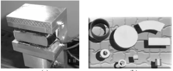
The magnetic field is typically generated by electromagnets, shown in Fig. 1(a) or permanent magnets as shown in Fig. 1(b). The magnetic field in the air gap of an electromagnet depends on the electrical current in the coil, the turns of the coil and the ferromagnetic material used in the core. So called metallically hard materials have a high coercitivity. After the magnetizing process, they deliver a permanent magnetic field.
(a) (b)
Figure 1. (a) Electromagnet example, (b) Kinds of permanent magnets.
Magnetic Field Evaluation
A magnetic field can be represented by means of field lines, where the tangent to the line, at any point, gives the direction of the field at that point, while the distance among lines gives the measure of the field magnitude. So, closer lines mean a more intensive magnetic field.
The Ampère Law establishes relation between current distribution and magnetic field. Initially developed by André Marie Ampère (1775-1836), this theory enables to find the solution for magnetic fields with highest symmetric degree, maintaining certain simplicity of solution and an academic severity at the same time (Eq. (1)):
¦ ³
¦
³HU.dlU i o Hcos(T)dl i (1)
o ³Hcos(
T
)dl ¦i o¦ ³Hcos(
T
)dl iThe Ampere Law is applied on a closed round or amperian curve. The magnetic field intensity is given by H, dl is the differential line segment and i is the liquid current involved by the curve.
The magnetic field intensity H creates a magnetic field B in any circumstance and condition. Such magnetic fields are related by a characteristic factor known as permeability coefficientP. The air permeability coefficient value is close to 4S x 10-7 (H/meter).
H
B P (2)
Solenoid
A filament rolled up as a helicoidal coil and crossed by an electric current defines a solenoid, which enables the application of Ampère Law, when considered ideal, to evaluate the magnitude of the resultant magnetic field. Figure 2 shows the solenoid center region where the magnetic field is the vectorial sum of the fields generated in each filament rolled up the coil.
Figure 2. Magnetic field lines in the vertical cross-section of the solenoid axis center.
tends to cancel for adjacent coils. In the center region, the field lines are practically parallel.
Considering an ideal solenoid, the magnetic field outside of the solenoid is practically zero, which allows the application of the Ampère Law for a square amperian curve (Halliday, Resnick, and Walker, 1996): Ni Hl i l d
H ¦ o
³ U. U (3)
Where l is the length of the square side, N is the number of coils in the amperian curve and i is the current crossing the coils. It is important to point out that during the integration along the curve, the external region of the solenoid presents H = 0 and consequently, the calculus Hcos(ș)l, to ș = 0 and 90 º is also zero. The quantity Ni is called the magneto motive force (F), and its unit is ampere-turns.
Equations (2) and (3) give the magnetic field generated by a solenoid:
l Ni
B P (4)
Where l is the length of the solenoid. The magnetic flux I (Wb) is defined as:
³BdA
I (5)
Considering a mean magnetic flux B perpendicular passing through the cross-section area A, the following expression is given:
BA
I (6)
So, from Eq. (6) and (4):
4
P
P
I
Ni A l Ni A l Ni / (7) where: P A l 1 P
(8)According to the previous definition, Ĭ is the magneto motive force. Consequently, represents the magnetic reluctivity and P, the magnetic permeance.
Magnetic Circuit and Air Gap
To conserve the magnetic field (B) in a magnetic circuit with an air gap the magneto motive force (Ĭ ) has to be rised to overcome the additional reluctivity. Figure 3 illustrates a magnetic circuit equivalent to a structure with air gap.
Figure 3. Magnetic nucleus with air gap (a) and an equivalent magnetic circuit (b).
For the design, special attention has to be paid to the magnetic flux density in the iron to avoid a saturation of the material which will lead to a change of its properties. The air gap instead, remains unsaturable, because of the linear magnetization curve of this material (µ constant).
According to Fig. 3 (b) the reluctivity concerning magnetic material and air gap can be evaluated from Eq. (8):
c c c c A l P g g g A l 0 P
(9)
Equation (7) gives:
g c Ni
I (10)
Ampère Law, Eq. (3), leads to Eq. (11):
g g c
cl H l
H
Ni (11)
Where c refers to the magnetic material and g refers to air gap.
µ0 is the air permeability coefficient.
The magnetic field can be estimated from Eq (6):
c c c A B I g g g A
B I (12)
The boundary effect present in this region of the magnetic field can be neglected to low values of air gap. In this way, the area Ac
can be approximated to the area Ag, and therefore:
c c g
A B
B I (13)
Magnetic Force
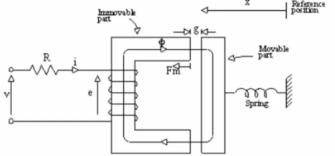
Considering the system in Fig. 4 composed by a fixed part, involved by N spiral coils, and a moving part connected to a spring. Applying a voltage in both ends of the coils, an electric current pass through the coils, generating an intensity of magnetic field H around each coil. The concept of equivalent magnetic circuit and the application of the Ampère Law gives Eq. (14):
Figure 4. Example of an electromecanical system.
g g c cl H l H
Ni (14)
NAB NI
O (15)
B the magnetic field, assumed the same for both regions. To a linear system: ¸¸ ¹ · ¨¨ © § 0 P Pcc g l l B
Ni (16)
Neglecting the magnetic reluctivity of the iron for Pc >> P0
and with lg = 2g. Eq. (16) simplifies to:
0
2 P
Bg
Ni (17)
When the number of coils N and the current i are known, the magnetic field B can be evaluated in the expression:
g Ni B
2
0
P (18)
In this case, the energy stored in the magnetic field is given by the Eq. (19):
Ag B B Wf 2 2 gap air of volume 2 0 2 0 2 u u P
P (19)
Taken into account that mechanical energy Wme is equal to the
energy stored in the magnetic field Wf, an infinitesimal displacement
dx results in a variation of dWme in mechanical energy. So, when Ȝ is
constant: dx x dW F dW dW dx F f m f me m ) ( (20)
The negative value of the force means the action of diminishing the air gap.
Equations (19) and (20) give:
0 2 0 2 2 2 P P AB F g A B dg d F m
m ¸¸
¹ · ¨ ¨ © § u u (21)
Equation (21) enables the evaluation of the magnetic force fm
through the magnetic field B (Sen, 1997). With Eq. (18) and Eq. (21) the magnetic force can be calculated by the current i and the air gapg.
2 2 2 0 4 g i AN
Fm P (22)
As Eq. (22) shows the electromagnet can only generate attracting forces. To generate a sinusoidal force that it is needed for modal analysis, either a push-pull configuration with two actuators on opposing sides of the shaft or a bias force is necessary. If the air gap is considered to be constant, for both cases the current i will then have to be the square root of the desired force signal, while for the case of negative forces the current has to be directed to the opposite actuator.
Frequency Behaviour of the Actuator
The current in the coil will follow the equation in the time domain: ) ( ) ( )
( R it
dt t di L t
U (23)
Where U is the applied Voltage; L is the inductance and R is the resistance of the coil. In the frequency domain this is:
) ( 1 1 ) ( or , ) ( ) ( Z Z Z Z Z Z j U j R L R j i j i R Lj j U (24)
It is important to highlight that Eq. (24) is valid only when the air gap remains constant. Hence, it is used for the explanation of the actuator dynamic behavior, when the frequency is varying. Experimental results and simulation of the dynamic behavior of the actuator is treated in the dynamic results section, using the Magnetic Force expression (Eq. 21 and 22) in the equation of motion (Eq 26).
For a constant RL-combination the current in the coils and thus the actuator force will decrease with the frequency rising of the voltage signal applied to the coil. The cut-off frequency fc is at:
L R
fc 2S (25)
A power Amplifier that delivers high voltages in combination with a current or a flux density controller is a useful approach to raise the cut-off frequency.
Experimental Assembly
Focusing on the validation of the forces generated by the magnetic actuator, a test rig as shown in Fig. 5 was assembled to analyse the achieved magnetic forces.
The reference measurement is achieved by force transducers on which a test shaft is mounted. The intention for the future operation is to estimate the actuator force on the basis of parameters of the actuator that can be achieved in an economical way to keep the actuator costs as low as possible.
In this sense, some variations were accomplished in the design parameters of the actuator, such as current, air gap and the operation frequency. The main objective is the evaluation of the influence of these parameters on the forces generated by the actuator.
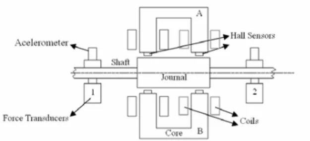
Figure 5. Assembly with two actuators.
Figure 6. Dimensions of the actuator-journal system.
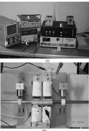
Figure 7(a) shows the experimental test rig with the signal generation system, the acquisition system and signal analyzer dedicated to the magnetic actuator monitoring. The magnetic actuator can be visualized in detail in Fig. 7(b).
(a)
(b)
Figura.7. (a) Experimental Assembly (A) signal generator, (B) oscilloscope, (C) power amplifier, (D) transducer circuit and (E) hall sensor circuit; (b) Magnetic Actuator.
Obtained Results
With the purpose of highlighting the influence of the mean input parameters of the magnetic actuator (current, air gap and frequency), experimental tests were carried out at several feasible levels of these parameters, leading to the estimation of the generated forces as well as the evaluation of the magnetic field in each case.
Static Tests
In the static tests a current was applied to the coils and the resultant magnetic force was evaluated. The main purpose of these
tests is to relate the actuator parameters as surface shape, input current and air gap to the magnetic force generated in the actuator.
In these tests an assembly at one side of the shaft was used as sketched in Fig. 6.
Surface Shape Effect: Regarding the surface of the actuator poles, there is the option of a flat and curved type. A curved surface like the one shown in Fig. 8 has the advantage that the air gap is constant in the cross section, which is easier to handle for the force evaluation. However it will be valid just for one shaft diameter.
Figure 8. Simulation of magnetic field for round surface.
A flat pole surface (Fig. 9) is more flexible in regards to various shaft diameters, but leads to difficulties in the force evaluation. While the flux density distribution across the air gap the curved pole is almost constant. Figure 9 shows, that for the flat pole it is not. Due to the varying air gap across the pole the magnetic reluctivity is also not constant and thus the magnetic flux will distribute itself accordingly. To calculate the actuator force with an applied hall sensor using Eq. (21) will now demand for an approximation of the mean flux density across the air gap. Such a distribution will probably not be constant for various air gaps. For the actuator without hall sensors an approximation of the average reluctivity across the pole will be necessary, to use Eq. (9) in the stated form. For both types (with or without hall sensors) a solution could be, to build up characteristic diagrams by FEM or/and experimental research to store the relation between either air gap, current or the measured flux density and the achieved actuator force.
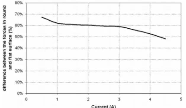
Further the actuator layout will have an influence on the effect. The difference between the obtained actuator force of a curved and a flat surface will decrease with greater magneto motive force as shown in Fig. 10, which was obtained experimentally, considering an air-gap of 2.5mm. When the material reaches its magnetic saturation, its reluctivity will rise. In the actuator pole this will lead to an equalization of the flux density distribution across the air gap (Fig. 11).
Figure 10. Percent difference between flat and round surfaces of the magnet ends.
Figure 11. Qualitative saturation curve for round and flat surface.
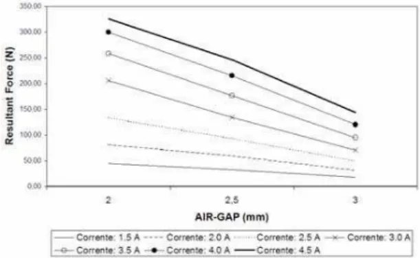
Further the difference between the forces of both surfaces will decrease with larger air gaps, because the variation of the reluctance in the air gap will sink (Fig. 12).
Figure 12. Influence of the air-gap in the force for round and flat surface.
The influence of the greater partial reluctivity will then decrease due to the greater overall reluctivity. A combination of partial saturation with a greater air gap then might show good results, but
will need a higher magneto motive force to overcome the larger reluctivity.
Current and air-gap influence: For the operation of the shown electromagnetic actuator, the most significant parameters are the current in the coils and the air gap between the actuator poles and the shaft. At a higher current, the magnetic field is stronger and for a constant air gap, the flux density and thus the actuator force will be higher (Fig 13).
When the magnetic saturation of the actuator material is reached, the magnetic reluctivity rises and thus the relation between the actuator force and the current decreases.
Figure 13. Simulated saturation curve.
Due to the lower reluctivity the flux density and thus the actuator force will rise with a decreasing air gap in quadratic relation. Figure 14 shows how the actuator force breaks in rapidly, if the air gap is raised from 0,5mm t o1,5mm for example to apply a hall sensor in that space.
Figure 14. Simulated force varying with the air-gap.
The experimental results show the same effects as the simulation predicts. Figures 15 and 16 shows experimental results of the actuator force for different air gaps and surface types (curved, flat).
Figure 15. Resultant force measured vs. variation of applied current.
Figure 16. Air-Gap influence in the resultant measured force.
The marked air gaps in Fig. 15 are thus to be understood as starting air gaps. The experiments however show one thing clearly, a force evaluation on the basis of Eq. (22) will lead to significant discrepancies in the results if a displacement of the shaft itself is neglected. An adequate sensor is essential to achieve accurate results with this method.
Force Evaluation: The force estimation is then done in two different ways:
1. The current is measured and the actuator force is calculated by using Eq. (22).
2. The magnetic flux density is directly measured with hall sensors in the air gaps and the force is evaluated with Eq. (21).
The flux density distribution in the air gap will be considered constant during each experiment. The following diagrams compare the estimated results for the flat and the curved pole surfaces to the measured forces by the force transducers.
Figures 17 to 19 show the results for the curved surface. The estimation by using the current method shows a significant deviation to the reference values. Compared at the maximum current of 4,5A the estimation error is about 60% for an air gap of 3mm, 45% for 2,5mm and ca. 35% for 2mm. At 2,5A the estimation error is 40% for 3mm, 55% for 2,5mm and 60% for 2mm air gap. For all cases, the estimation error is very large and not useful for a precise force measurement needed for modal analysis. The large error supposable comes due to the neglect of the shaft displated as proposed before. With large currents, a magnetic saturation of the material occurs (Fig. 17). This compensates the effect slightly, but the estimation error is still too big and the compensation effect depends on too many parameters as that it would promise to lead to robust force estimation on this way.
Figure 17. Force estimation to air-gap of 2 mm - ends round surfaces.
Figure 18. Force estimation to air-gap of 2.5 mm - ends round surfaces.
Figure 19. Force estimation to air-gap of 3 mm - ends round surfaces.
However literature shows that by using the current-air gap method, accuracies of 5-10% are achievable.
Much more promising are the results for the force estimation with applied hall sensors. The estimation error for high currents of 4.5. A reach values of about 10% for air gaps of 3mm and 2,5mm and about 20% for an air gap of 2mm. At lower currents of 2,5A the estimation error is about 20% at 3mm air gap and ca. 15% at 2,5mm and 2mm air gap. While the achieved quality seems to be rather insensitive to changes of the air gap at medium current levels, saturation effects occur at higher current levels and lead to higher estimation errors.
The experiments with the flat pole surface show, what the simulation predicted (Fig. 20 and Fig. 21). The actuator force that is estimated by the measured flux density is much higher than the achieved value. As only one hall sensor was applied in the center of the pole surface, it will sense the maximum value that occurs in the air gap (see Fig. 9). The flux density and thus the local force will decrease towards the edges, leading to a lower actuator force.
estimation quality can be completely different for another set of parameters.
Figure 20. Force estimation to air-gap of 2 mm - ends flat surfaces.
Figure 21. Force estimation to air-gap of 2.5 mm - ends flat surfaces.
Dynamic Tests
The objective of the dynamic test is the experimental evaluation of the dependency of magnetic force and magnetic field on frequency. In these tests both actuators were used, as shown in Fig. 6. These actuators are in opposite sides, that means normal forces in the shaft plane. Each actuator performs only attraction forces. Then, to excite the shaft in a plane both actuators should work in synchrony.
Considering the main objective is the evaluation of the parameters tendency and the design characteristics of a magnetic actuator, a parameter that certainly should be studied is the excitation frequency. This device development seeks the application of external excitation in rotating systems, allowing proceeding with a modal analysis without contact between exciter and journal.
The excitation by the actuator applies a harmonic force to the shaft. As an electromagnet will always apply attracting forces to the shaft, the direction of the field and, thus, the current in the coils, must be applied unidirectionally.
Also the mechanical behavior of the shaft will have an influence on the force, because the magnetic field in the electromagnet depends on the air gap (Eq. 21). A flexible shaft or bearing, which allows high oscillations of the shaft in the actuator region, leads to an oscillating air gap and thus there is an effect on the magnetic and electric behavior of the actuator.
The results of the following experiments demonstrate the interaction among electrical, magnetic as well as mechanical behavior and show how important it is to take into account magnetic actuator and shaft as a mechatronic system.
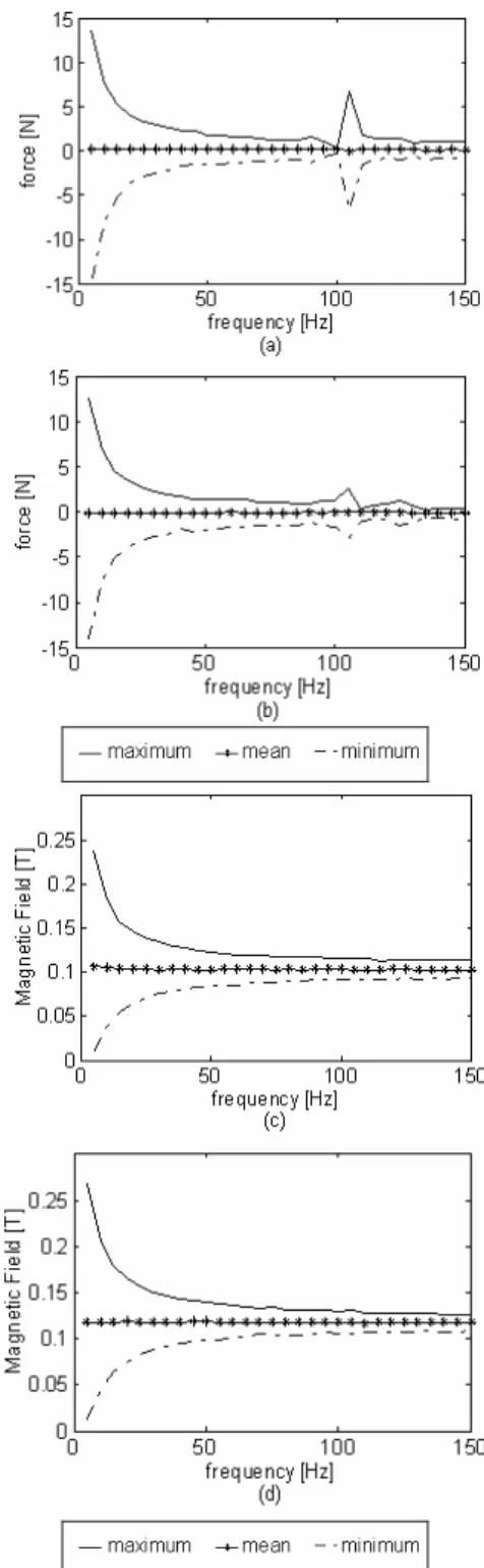
Figure 22 shows the influence of the excitation frequency increasing on the maximum, mean and minimum values of the magnetic forces (Fig. 22(a) and 22(b)), and the magnetic field (Fig. 22(c) and 22(d)), using an external voltage of 5V in each coil. The results are obtained using force transducers to obtain the magnetic
forces, and applying hall sensors to obtain the magnetic field. The mean values are not influenced by the frequency variation. However, the maximum and minimum values of force and magnetic field tend to approximate the mean value with the increasing of the frequency.
Moreover, a peak in the force transducers signal can be noticed close to 105 Hz, indicating the natural frequency of the mechanical system, due to the increasing of amplitude acquired by the transducers, which measure the force based on the imposed displacement.
This phenomenon can not be detected by hall sensors, because they are able to measure the magnetic flux density acting on the system and thus they are insensitive to estimation errors due to a varying air gap.
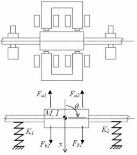
In order to verify the dynamic of the whole system, the mechanical model presented in Fig. 23 was taken into account. This system is modeled by Eq 26.
2 4
2
2 2 1 1 2
2 1
2 1 2 1 2 1
b F F F F b a K K I
F F F F x K K x M
b a b a
a a b b
T T
(26)
Where a and b are shown in Fig. 6, M is the mass of the system (M = 0.82 kg) and I is the mass moment of inertia (I =2.21.10-3 kg.m2). The stiffness of each transducer and of the shaft are represented by K1andK2 (K1=K2=178 kN/m). The magnetic forces
are represented by Fa1,Fa2,Fb1 and Fb2. The generated coordinates
are the displacement x and the angle ș.
Considering the Eq. (22) to estimate the forces, the system response was simulated for a sinusoidal excitation frequency of 20 Hz with a magnitude of 3 A, as shown in Fig. 24.
Figure 23. Mechanical dynamic system
Figure 24. System response for simulated force.
As the simulated magnetic force are equal in both arms of the actuator (Fa1 = Fa2andFb1= Fb2), it is noticed that angle ș is always
zero.
Afterwards, the experimental magnetic field obtained as shown in Fig. 22 (c) and (d) is used to estimate the forces by Eq. (21) and applied in Eq. (26), in order to obtain the displacement x and angle ș with experimental measurements.
Figure 25 shows the system response for a frequency of 20 Hz, using the measured magnetic field.
Figure 25. System response for experimental magnetic field.
The displacement in Fig. 24 and 25 are in a range between 20 and 30 µm, showing a similarity between the reponses.
Moreover, the response shows in Fig. 25 that the angles are always very small. Because of that, it is possible to neglect this degree of freedom and consider only the displacement to model the system.
Conclusion
The main focus of the paper is to investigate the design of a low-cost contact free force actuator to excite a rotordynamic system fir the purpose of a modal analysis. The following steps were accomplished:
With respect to the design of the actuator, surfaces round and flat actuator poles were investigated. A previous advantage of the flat pole surface is the fact that it can be applied to different shaft diameters, but the accuracy depends on actuator end/shaft diameter dimension ratio.
Air-gap as well as current influence on the actuator force has been investigated by simulations and experiments. The air gap variation due to the flexible rotor motion leads to an interaction between both parameters.
A simulation with the current air-gap method was done. The comparison to the measured results shows that the air-gap has to be monitored to achieve accurate results. A neglect showed about 50% estimation error. Much better results were achieved by the application of hall sensors to measure the magnetic field density inside the poles of the actuator. Without calibration, accuracies of about 10% could be achieved.
Experiments with sinusoidal signal were accomplished between 5 and 150 Hz. The value of achievable force dramatically reduces due to the inductivity of the coil in the electrical circuit, limiting the feasible frequency range of operation in the actual test rig. The application of stronger power amplifiers can solve the problem.
displacement of the geometric center of the system journal-actuator and the journal tilting angle.
These results show very clear how important it is to consider a magnetic force and the rotor dynamic as a mechatronic system, where interactions between electrical, magnetic and mechanic systems occur.
Although the applied force will be known in every operation state by the measurement of the actual flux density via the hall sensors, a control circuit for the flux density should be developed to assure that the actuator force is independent of the interaction with the mechanical system. This will be an advantage for the modal analysis.
Acknowledgments
The authors would like to thank CAPES/DAAD Probral program to support this research, and also CNPq and FAPESP. This work would not be accomplished without the technical and logistic support of TUD Darmstadt and UNICAMP Campinas.
References
Aenis, M., 2002, “Einsatz aktiver Magnetlager zur modellbasierten Fehlerdiagnose in einer Kreiselpumpe“ – Dissertation, Technische Universität Darmstadt, Shaker Verlag, Aachen.
Aenis, M., Nordmann, R., 1999, “A precise force measurement in magnetic bearing for diagnostic purpose” – 5th International Symposium on Magnetic Suspension Technology, Santa Barbara, USA.
Christensen, R. H., Santos, I.F., 2005, “Control of rotor-blade coupled vibrations using shaft-based actuation”, Proceedings of the XI DINAME, Ouro Petro, Brasil, pp. 1-9.
Demierre, M., Pesenti, S., Frounchi, J., Besse, P.A.,Popoviü, 2002, “Reference magnetic actuator for self-calibration of a very small sensor array”, Sensor and Actuator A, Vol. 97-98, pp. 39-46.
Garnier, A., Bououina, T., Fujita, H., Hiramoto, T., Orsier, E., Peuzin, J.-C., 2000, “Magnetic actuation of bending and torsional vibrations for 2D optical-scannner application”, Sensors and Actuator A, Vol. 84, pp. 156-160. Halliday, D., Resnick, R., Walker J., 1996. “Fundamentos de Física 3”. 4ª ed. Rio de Janeiro: LTC-Livros Técnicos e Científicos Editora S.A., 350p.
Howe, D., 2000, “Magnetic actuators”, Sensor and Actuators A., Vol. 81, pp. 268-274.
Hsiao, F.-Z., Lee, A.-C., 1994, “An investigation of the characteristics of eletromagnetic bearing using the finite element method.”, Transaction of the ASME, Vol. 116.
Jang, M. J., Chen, C.L., Tsao, Y. M., 2005, “Sliding mode control for active magnetic bearing system with flexible rotor”, Journal of Franklin Institute, Vol. 342, pp. 401-419.
Ji, J. C., 2003, “Dynamics of a Jeffcott rotor-magnetic bearing system with time delays”, Non-linear Mechanics, Vol 38, pp. 1387-1401.
Klessen, C., Nordmann, R., Schönhoff, U., 1999, “Design of a minimum current magnetic bearing” – 5th International Symposium on Magnetic Suspension Technology, Santa Barbara, USA.
Klessen, C., Nordmann, R., 1999, “Entwicklung kostengünstiger Magnetlager.“ – Antriebstechnik, Zeitschrift für Konstruktion, Entwicklung und Anwendung von Antrieben und Steuerungen.
Lovera, M., Astolfi, A., 2004, “Spacecraft attitude control using magnetc actuators”, Automatica, Vol. 40, pp. 1405-1414.
Pasquale, M., 2003, “Mechanical sensors and actuators”, Sensors and Actuators A, Vol 106, pp. 142-148.
Sen, P. C., 1997, “Principles of Electric Machines and Power Electronics.” 2nd ed.John Wiley & Sons, 615 p.
Siegwart, R., Traxler, A., 1997, “Active Magnetic Bearings. Basics and Applications.” Update 5.97 special. – Winterthur: MECOS Traxler AG.