Article
Printed in Brazil - ©2017 Sociedade Brasileira de Química0103 - 5053 $6.00+0.00*e-mail: [email protected]
Development of Three-Dimensional Electrodes of PbO
2Electrodeposited on
Reticulated Vitreous Carbon for Organic Eletrooxidation
Rosimeire M. Farinos, Rafael L. Zornitta and Luís A. M. Ruotolo*
Departamento de Engenharia Química, Universidade Federal de São Carlos, P.O. Box 676, 13565-905 São Carlos-SP, Brazil
The application of electrochemical technology for the degradation of organic pollutants often faces two main problems, related to the anode material and mass transport limitations. Although PbO2 electrode is inexpensive and provides satisfactory electrooxidation kinetics, in the form of
plane electrodes it is unable to resolve the mass transfer problem that arises at low concentrations of organics. In this work, an electrochemical flow reactor was developed for the preparation of three-dimensional electrodes consisting of PbO2 films electrodeposited onto reticulated vitreous
carbon. The electrodes were characterized in terms of the substrate coating, morphology, structure, and electrocatalytic activity in the decoloration reaction of Reactive Blue 19 dye. The results showed that it was possible to deposit a uniform film of PbO2 on the surface of the substrate after
optimization of the current density and deposition time (0.7 mA cm-2 for 30 min). Comparison of
the plane and three-dimensional electrodes revealed that the turbulence generated by the porous matrix significantly accelerated the dye decoloration kinetics, increasing 3.3-fold the first order kinetic constant (from 0.010 min-1 for VC/PbO
2 to 0.033 min-1 for RVC/PbO2).
Keywords: three-dimensional anodes, lead dioxide, organic electrooxidation, mass transfer
Introduction
Human activities now generate a broad range of organic pollutants. Many of these compounds are not biodegradable and therefore require physical-chemical treatments for
complete degradation to CO2 and H2O, or for conversion
to organic compounds that are biodegradable. Furthermore, the presence of organic pollutants in water bodies can have
significant environmental and human health impacts,1,2 as
well as economic implications (because noncompliance with environmental laws can result in heavy fines).
The processes used for the treatment of recalcitrant organic pollutants include advanced oxidation processes (AOPs), which involve the generation of hydroxyl radicals
(HO).3,4 Although these processes can often be effective,
they have drawbacks related to their storage and the consumption of chemicals, and in the case of techniques such as photocatalysis, there are difficulties in scaling-up. The search for new processes for treating effluents containing organic compounds has intensified, often driven by the need to reuse water within the process itself, or to comply with the emission standards set in environmental legislation.
The electrochemical oxidation of organic pollutants offers a versatile alternative for the treatment of aqueous effluents, since, in most cases, it does not involve the use of chemical products, it is easy to implement and maintain, and enables simple scale-up. Furthermore, electrochemical technology is environmentally friendly,
because the main reagent used is the electron.5,6 However,
in order to make it viable for use in industrial oxidation of organic pollutants, it needs to aim at reducing capital and energy costs by optimizing the efficiency of degradation, while at the same time minimizing energy consumption.
The use of electrochemical reactors that employ stable anodes enables the generation of weakly adsorbed
hydroxyl radicals able to oxidize organic matter.7 Among
the anodes that provide excellent results in terms of electrooxidation of organic molecules are those that have a high overpotential for the oxygen evolution reaction
(OER). Boron-doped diamond (BDD), SnO2-Sb, and PbO2
anodes are suitable for this purpose.8 However, although
the BDD is chemically stable and shows excellent results in
the degradation of organic compounds,9-11 it is expensive,
while the SnO2-Sb electrode becomes deactivated after a
period of use.12 On the other hand, the PbO
be easily prepared by electrodeposition, is inexpensive to manufacture, and shows good electrochemical activity. It is stable at high potentials as well as in media with
different pH values.8,13,14
Despite the advantages of electrochemical technology, its main disadvantage concerns the high consumption of
energy resulting from low current efficiencies,7,15 which in
turn are a direct consequence of mass transport restrictions caused by the low concentrations of organic compounds in
effluents.16-18 In applications involving the electrochemical
removal of metal ions present in dilute aqueous solutions, this problem can be circumvented by the use of
three-dimensional cathodes.19,20 In addition to high specific
surface area, these cathodes also provide high interstitial velocities that generate turbulence and significantly increase the mass transfer coefficient. However, in the case of electrochemical systems for the treatment of organic compounds, the use of three-dimensional electrodes is often limited by the choice of porous substrate material to be used, which should be resistant to anodic corrosion and be easily coated by the deposition of electroactive material onto its surface.
Recio et al.21 reported the preparation of reticulated
vitreous carbon (RVC) electrodes coated with PbO2
films, opening new perspectives for the application of three-dimensional anodes in effluent treatment. Here, the percolation of the electrolyte through a porous electrode allows the reaction to occur with high mass transfer rates on a large specific surface area. Reticulated vitreous carbon is a highly suitable material for use in three-dimensional electrodes, and can serve as an excellent substrate for the
electrodeposition of electroactive films (such as PbO2),
because its surface area can be as high as 6600 m2 m-3 and
it provides negligible pressure drop (since it consists of approximately 97% of empty space). It also offers excellent
levels of chemical inertness and electrical conductivity.22,23
Although the good results reported by Recio et al.,21 there
still remains the need to optimize the operational variables and the electrochemical reactor used for the electrochemical
synthesis of PbO2 on RVC.
This work concerns the preparation of a
three-dimensional PbO2 electrode deposited on a 45 ppi
(pores per inch) RVC substrate using a flow reactor. The
effects of current density and electrodeposition time were studied in order to obtain a uniform coating. The electrodes were characterized in terms of their structure,
morphology, and uniformity of the PbO2 electrodeposit. The
electrochemical characteristics were analyzed by means of the electrochemically active area, and the electrocatalytic activity was evaluated indirectly using the kinetics of decoloration of Reactive Blue 19 dye.
Experimental
The PbO2 film on the RVC substrate was produced using
an electrolyte (pH 1.4) containing 0.1 mol L-1 Pb(NO
3)2
(Sigma-Aldrich), 0.1 mol L-1 HNO
3 (Synth), and 0.5 mg L-1
SLS surfactant.24 The temperature used was 65 °C. All
solutions were prepared with deionized water.
The decoloration procedure employed a solution
(pH 4.7) containing 30 mg L-1 Reactive Blue 19 dye (RB 19)
(Sigma-Aldrich) and 0.5 mol L-1 Na
2SO4 (Qhemis) as
supporting electrolyte.
The three-dimensional substrate used for deposition
of the PbO2 film was RVC with porosity of 45 ppi and
dimensions of 0.5 cm (thickness) × 2.5 cm (width) × 2.5 cm (length) (Figure S1). The specific surface area
value (28.5 m2 m-3) was provided by the manufacturer
(Electrosynthesis Company). For both the production
of the PbO2 films and for the experiments involving the
decoloration of RB 19, a dimensionally stable Ti/Ti0.7Ru0.3O2
anode (De Nora do Brasil) was used as the current collector and an AISI 316 stainless steel plate was used as the counter electrode. Both electrodes had dimensions of 2.5 × 2.5 cm.
Experimental setup
The electrodeposition of the PbO2 film on RVC
was performed using the experimental system shown in Figure S2. The electrolyte circulated through the electrochemical reactor in a closed system, driven by a peristaltic pump (BP 200D, Tecnopon). A current source (3003D, Minipa) was used to supply a constant electric current to the reactor. A multimeter was connected to the reactor to read the cell potential during the process, and an ultra-thermostatic bath (SL-152, Solab) maintained a constant electrolyte temperature. A magnetic stirrer was used to ensure that the electrolyte solution remained homogeneous during the experiment.
The same electrochemical reactor was used in the study of decoloration of the RB 19 dye, but in this case, the
RVC/PbO2 electrode had dimensions of 2.5 × 1.0 × 0.5 cm.
The experimental device was composed of the components shown in Figure S3. The solution containing the dye circulated through a flow cuvette coupled to a UV-Vis spectrophotometer (Ultrospec 2100 Pro, Amersham Pharmacia), and absorbance measurements were recorded in real time.
Electrochemical reactors
Figure 1 shows a detailed view of the flow reactor used
photograph of the reactor, which consisted of juxtaposed rectangular acrylic plates, sealed with coatings of silicone and assembled using nuts and bolts. The current collector was built into the left-hand plate shown in Figure 1. The counter electrode was covered with a polyethylene mesh coated with polyamide fabric (5) to avoid short circuit of the system. The counter electrode was built into the right-hand plate (6). The contact between RVC and current collector was made by pressing when the rector was assembled. The electrolyte flow was perpendicular to the electric field, in a flow-by configuration. The electrochemical reactor used for decoloration of the RB 19 dye had the same characteristics as the reactor used in the electrochemical synthesis, but the central plate had a smaller volume to accommodate an electrode with dimensions of 2.5 × 1.0 × 0.5 cm.
The RVC substrates were first immersed for 10 min in a 3:1 (v/v) solution of sulfuric acid and hydrogen peroxide. This pretreatment was used to increase the hydrophilicity of
the RVC surface.25 After the pretreatment, the electrodes were
washed with deionized water and dried at room temperature.
Experimental procedures
The PbO2 films were produced under different
experimental conditions of current density (j) and electrolysis time. The values of j were calculated based on the specific surface area and chosen based on previous experiments. The electrodeposition was performed using the flow reactor and system shown in Figures 1 and S2, respectively. The experimental procedure involved the
galvanostatic electrodeposition of PbO2, according to the
experimental conditions of the 22 + central points factorial
design shown in Table 1. The central points, RVC/PbO2-3
and RVC/PbO2-4, were used to estimate the pure error.
The temperature and flow rate of the electrolyte
were kept constant at values of 65 °C and 25 mL min-1,
respectively. The volume of electrolyte used was 80 mL. The electrolyte was pumped by the peristaltic pump into the base of the reactor and then returned to the reservoir. After the pre-established electrodeposition time, the position of the RVC in the reactor was inverted in order to try to ensure that both sides of the electrode were covered.
The electrocatalytic activities of the electrodes were evaluated in the decoloration of RB 19, whose molecular structure is shown in Figure S5, together with the function of each part of its structure. Evaluation was made of the effect of applied current density i, which is calculated considering
the projetcted electrode area (6.25 cm2), on the decoloration
kinetics, using the flow reactor shown in Figure 1. The flow
rate and temperature were kept constant at 25 mL min-1 and
30 °C, respectively. The experimental procedure consisted of circulating the electrolyte containing the dye through the electrochemical reactor and applying the desired current density. The electrolyte exited the reactor and then passed through a flow cuvette, where the absorbance of the solution (at 600 nm) was measured every 30 s.
The plots of the normalized absorbance (A/A0) as a
function of time t were fitted using a pseudo-first order kinetic model (equation 1), and the values of the kinetic
constants (kd) were determined by means of exponential
regression using the Levenberg-Marquardt method.
(1)
The decoloration efficiency (εD) was defined as the ratio
between the color change (A0 − A) observed at a given time
and the electric charge supplied (Q) (equation 2).
(2)
Characterization of the RVC/PbO2 electrode
Analysis of the coating of the RVC substrates achieved
by electrodeposition of PbO2 was performed using a
Figure 1. Schematic representation of the electrochemical reactor.
Table 1. Experimental conditions for PbO2 electrodeposition onto the
RVC substrate
Electrode j / (mA cm-2); I / mA t / min
RVC/PbO2-1 0.7; 62 20
RVC/PbO2-2 0.7; 62 30
RVC/PbO2-3 0.9; 80 25
RVC/PbO2-4 0.9; 80 25
RVC/PbO2-5 1.1; 98 20
RVC/PbO2-6 1.1; 98 30
scanning electron microscope (XL30 FEG, Philips). A schematic illustration of the surface of the electrode used in the microscopy analyses is shown in Figure S6.
Characterization of the structures of the films produced
was performed by triturating the RVC/PbO2 electrodes
followed by analysis using a Siemens D5005 X-ray
diffractometer. The scan rate was 2º min-1 in the range
20º ≤ 2θ≤ 80º. The diffractograms obtained were compared
to JCPDS card standards.
The electrochemically active area was determined using Cottrell’s equation (equation 3), which describes the behavior of the electric current when a potential step is applied to the electrode in the region where the reaction
is controlled by mass transport.26
(3)
In equation 3, It is the current (in A) at a given
time t, n is the number of electrons exchanged in the oxidation or reduction reaction, F is the Faraday constant
(96485 A s mol-1), EAA is the electrochemically active
area of the electrode (in cm²), C* is the concentration
of the electroactive species ([Fe3(CN)6]-3 was used at a
concentration of 1.0 × 10⁻⁶ mol cm-3), and D
0 is the diffusion
coefficient of the oxidized species (3.93 × 10⁻⁵ cm2 s-1).
The EAA values of the 45 ppi RVC and the RVC-PbO2-2,
RVC-PbO2-3, and RVC-PbO2-5 electrodes were measured by
immersing a 0.5 cm3 (1.0 × 1.0 × 0.5 cm) of the electrode in
a solution containing 0.1 mol L-1 of potassium ferricyanide
and potassium chloride, adjusted to pH 3. A platinum
plate (2.5 cm2) was used as the counter electrode. For each
electrode, chronoamperometry was performed for 50 s. During the first 15 s of this analysis, application of a potential
of 0 V vs. Ag/AgCl allowed formation of the electrical double
layer. Subsequently, a potential of 1.0 V vs. Ag/AgCl was
applied, which was monitored until the end of the established period. This procedure was repeated five times.
The results showed an exponential decay of the current as a function of time. These results were then linearized based on equation 3. The EAA values were then determined
from the angular coefficients (B) of the plots of It as a
function of t1/2.
Results and Discussion
PbO2 electrodeposition
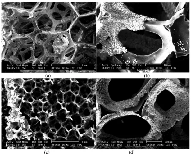
SEM images of the electrodes produced by applying
current densities of 0.7 and 0.9 mA cm-2 are shown in
Figure 2.
The morphologies of the deposits obtained by applying
current densities of 0.7 and 0.9 mA cm-2 were typical of
β-PbO2, although the degree of coverage of the substrate
was strongly dependent on the current density and the electrodeposition time. Figure 3 shows a schematic illustration of the coating of the electrodes under the conditions shown in Figure 2. The thinner lines indicate the substrate, while increasing thickness of the lines indicates
deposition of the PbO2 film, with the thickness of the line
being proportional to the thickness of the film.
The RVC/PbO2-1 electrode showed preferential coating
in a narrow region at the end of the electrode near the counter
electrode, while there was no formation of PbO2 film in
the central region. However, when the current density was maintained constant and the deposition time was increased,
a complete coating of the RVC/PbO2-2 electrode was
observed, with an estimated increase of film thickness at the ends of the substrate from ca. 3.8 to ca. 7.5 µm. When
a current density of 0.9 mA cm-2 was applied (RVC/PbO
2-3
and RVC/PbO2-4), there was a further increase in thickness
(to ca. 8.8 µm), but the deposition time was not sufficient to ensure complete covering of the substrates.
Figure 4 shows the micrographs obtained for the electrodes prepared by applying a current density of
1.1 mA cm-2. Application of a higher current density
(RVC/PbO2-5) resulted in the formation of a PbO2 layer with
thickness of ca. 7.7 µm at the ends of the RVC substrate, although a large part of the substrate still remained uncoated, which could be attributed to the short deposition time. However, even when the electrodeposition time was
increased from 20 to 30 min, greater deposition of PbO2 was
observed on the ends of the substrate (Figures 4c and 4d), with a film thickness of ca. 24 µm, while the RVC surface remained uncoated in the central region. It is important to note that the thickness values are approximate and were obtained for a reference position located around 0.5 mm from the outer edge of the electrode. In summary, a higher current density intensified the phenomenon of increased film thickness at the extremities of the substrate, but did not ensure complete and uniform coating of the substrate.
These results can be explained by the uneven distributions
of potential and current on porous electrodes.27-33 A similar
effect was also observed on the cathodic electrodeposition of polyaniline films on RVC substrates. Similar to
the polyaniline film, the current density for PbO2 film
electrode, so that the thickness of the coating in these regions is also greater.
Based on the SEM images and considering the experimental measurements of potential inside the RVC
electrode performed by Ruotolo and Gubulin.31,32 Figure 5
shows a schematic illustration of the effect of current on the expected potential profile inside a porous electrode.
Increasing the applied current caused a disproportionate increase in electrode potential in the regions close to
current collector (CC) and counter electrode (CE). The potential became more positive in the region close to CE, resulting in a thicker film in this region, while the coating became thinner and more irregular close to CC, in agreement with the experimental observations. An increase in electrodeposition time led to an improved coating in the region close to CC, but the effect of the intense field close to CE resulted in the deposition of
very thick films of PbO2 in this region, which could
Figure 2. SEM micrographs of PbO2 films obtained by electrodeposition onto 45 ppi RVC. (a) and (b) RVC/PbO2-1: j = 0.7 mA cm-2 and t = 20 min;
cause detachment of the film. Therefore, the use of lower currents seemed to be more appropriate, because this avoided the occurrence of highly anodic potentials close to CE, hence preventing the formation of very thick films in this region. To ensure complete coating of the electrode, a longer electrodeposition time should be used when lower current densities are applied.
The influence of the substrate coverage and the
morphology of the PbO2 film on the electrocatalytic
properties of the electrode were indirectly evaluated using the decoloration reaction of Reactive Blue 19 dye.
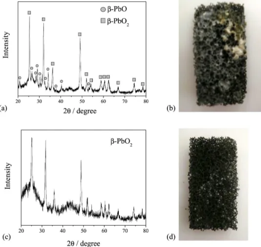
When a current density of 1.1 mA cm-2 was applied,
the formation of a yellow deposit was observed on the outer surface of the electrode (Figure 6b), different to the
typical dark gray color of the PbO2 film (Figure 6d). The
X-ray diffraction (XRD) pattern for this electrode, shown in Figure 6a, revealed the formation of a small amount
of β-PbO, although the predominant oxide phase was the
desired β-PbO2, which is the most electrochemically active
phase for use in the oxidation of organic compounds. The
XRD analysis of the RVC/PbO2-2 electrode revealed the
presence of the β-PbO2 phase alone (Figure 6c).
Decoloration of RB 19 dye
Figure S7a shows typical absorbance spectra obtained for the solution containing the RB 19 dye before and after
the process of decoloration using the RVC/PbO2-2 electrode,
which was the electrode that showed the best coverage of the substrate. The spectrum for the initial solution showed three absorbance bands, one at 600 nm, attributed to the anthroquinone chromophore group responsible for the color Figure 3. Schematic representation of the RVC electrodes covered with
PbO2 film, shown in Figure 2. CC = current collector; S = separator; and
CE = counter electrode.
Figure 4. SEM micrographs of PbO2 films obtained by electrodeposition on 45 ppi RVC. (a) and (b) RVC/PbO2-5: j = 1.1 mA cm-2 and t = 20 min;
of the dye, and the others at approximately 230 and 300 nm,
related to π→π* transitions of the aromatic rings.24
The final solution spectra obtained at a wavelength of 600 nm, corresponding to the blue color of the RB 19 dye, revealed that the color decreased with increase of the
current density (Figure S7b). Bands in the 230 < λ < 300 nm
region decreased to a lesser extent, indicating that a small fraction of the molecules could have been degraded to aliphatic acids, or even mineralized, as also observed by
Andrade et al.24
Figures 7a and 8a show typical plots of decoloration
(expressed in terms of the normalized absorbance, A/A0) as
a function of time and the charge consumed, respectively, for different current densities. In all cases, the decoloration kinetics followed pseudo-first order exponential decay of the absorbance. This behavior is typical of processes controlled by mass transport, where increased current density results in a loss of efficiency of the process, as confirmed in Figure 8, in which, with the same charge, more decoloration was achieved by applying low current densities. In order to compare the decoloration kinetics of all the electrodes produced under the different current density conditions, the plots of decoloration against time were fitted according to equation 1 in order to determine
the decoloration kinetic constant, kd. The results are shown
in Figure 7b.
The kd values were analyzed statistically considering
a significance level of 5%. The results indicated that the only variable that had a statistically significant effect on the decoloration was the applied current density. As expected,
an increase of i caused an increase of kd, since a higher
charge was supplied to the process. However, as shown Figure 5. Schematic representation of the potential distribution for an
anodically polarized porous electrode.
Figure 6. (a) X-ray diffraction pattern of the RVC/PbO2-6; (b) photograph of the RVC/PbO2-6; (c) X-ray diffraction pattern of the RVC/PbO2-2; (d)
in Figures 7 and 8, faster decoloration kinetics was not accompanied by an increase in decoloration efficiency, indicating that the process became less efficient when the current density was increased and that a large fraction of the supplied charge was used in parallel reactions, leading to greater energy consumption. However, the most surprising observation was the absence of any effect of the synthesis variables (j and t) on the decoloration process, indicating that for the same value of i, the electrodes exhibited decoloration kinetics that were statistically the same, with the small differences attributed to experimental variability. Two important conclusions can be drawn
from these findings: (i) the electrochemical reaction only
occurred on the external surface of the electrode, in the
region close to CE, and (ii) the thickness of the PbO2 film
did not have any influence on the electrooxidation process. The first conclusion can be easily confirmed by analyzing,
for example, the RVC/PbO2-1 and RVC/PbO2-2 electrodes
(Figure 2), because while the former only had a coating of
PbO2 film on the extremities of the substrate, the latter was
completely covered, suggesting that it should provide better performance in the decoloration. However, this was not observed experimentally, which can once again be explained
by the uneven distribution of potential and current on the porous electrode (Figure 5). Hence, the same mechanism
that caused the PbO2 film to grow preferentially on the ends
of the electrode close to CE also caused the decoloration reaction to occur with greater intensity in this region, so that a large part of the electrode remained less active (or virtually inactive) for the electrochemical reaction. The fact that the electrode was not fully covered was therefore not a determining factor in the reaction kinetics.
The EAA results (Table 2) also supported the notion that the electrodes possessed similar electrocatalytic activities.
The presence of the PbO2 film resulted in increases in EAA
of approximately 7 to 8-fold, compared to the plain RVC substrate. However, no significant difference was observed between the completely or partially coated electrodes, considering the standard deviation of the samples. The
substantial variability observed for the RVC/PbO2-5
electrode could be attributed to the greater morphological complexity of the film on this electrode, as well as to the presence of other oxides on its surface. Once again, it could be concluded from these results that only one region of the electrode was electroactive (the region near the counter electrode).
Figure 7. (a) Normalized absorbance as a function of time and (b) decoloration kinetic constant values for RVC/PbO2 electrodes prepared
using different conditions of j and t.
Regarding the second conclusion, and comparing, for
example, the RVC/PbO2-3 and RVC/PbO2-6 electrodes
(Figures 2 and 4), it is apparent that neither electrode was
fully coated and that the thicknesses of the PbO2 films
in the regions near the extremities of the substrates were
very different (8.8 and 24 µm for the RVC/PbO2-3 and
RVC/PbO2-6 electrodes, respectively). However, the
decoloration kinetics values were almost the same, showing
that the film thickness had no effect on kd and indicating
that the electrochemical reaction only occurred on the outer
surface of the PbO2 film. Analysis of the morphologies of
the PbO2 films revealed that the films were very compact,
preventing permeation of the solution through the film, so that the only electroactive area was the external surface in direct contact with the electrolyte.
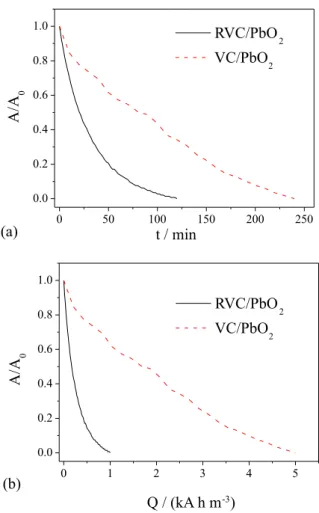
Despite the fact that the three-dimensional RVC/PbO2
electrode presented a small electroactive area, relative to the total area of the substrate, the decoloration obtained with the
porous RVC/PbO2 electrode occurred much more rapidly
(in approximately half the time), compared to the use of
a plane PbO2 electrode (VC/PbO2), as shown in Figure 9.
This indicated that the effect of the area and the generation of turbulence by the three-dimensional matrix resulted in substantial enhancement of the process. The advantages of using the three-dimensional electrode become even more evident when the efficiency with which the supplied charge was used is taken into consideration, Figure 9b. In this case, the use of the three-dimensional provides a huge increase of current efficiency.
With regard to the presence of lead in the solution, analyses of the final solutions after the electrolyses under different conditions of i revealed average concentrations
of 1.88 ± 0.07 mg L-1 and 1.35 ± 0.33 mg L-1 for the
RVC/PbO2-1 and RVC/PbO2-2 electrodes, respectively.
When the value of j used in the electrode preparation step was increased, the concentrations of lead in solution
increased to 2.55 ± 0.40 mg L-1 and 2.43 ± 0.36 mg L-1 for
the RVC/PbO2-2 and RVC/PbO2-3 electrodes, respectively.
The highest lead concentrations were observed for the
RVC/PbO2-5 and RVC/PbO2-6 electrodes, with values of
6.05 ± 3.38 mg L-1 and 6.53 ± 3.55 mg L-1, respectively. It
can be concluded that the use of higher values of j during
electrodeposition of the PbO2 film resulted in a higher
final concentration of lead in the solution, which could be explained by the greater film thicknesses observed at the extremities of the electrodes, leading to lower chemical
stability. In the case of the RVC/PbO2-5 and RVC/PbO2-6
electrodes, the presence of β-PbO could also have been
responsible for the higher values of Pb2+ in solution.
Despite these results, the RVC/PbO2-2 electrode showed no
loss of electrochemical activity when it was used in other electrolyses. This indicated that the small quantities of lead detected in the solution were probably not derived from the
PbO2 film, but rather from the release of lead ions that had
not been removed during the electrode washing procedure and had been retained in the structure of the film.
Conclusions
Three-dimensional electrodes were produced by
electrochemical coating PbO2 onto RVC in a flow reactor.
The quality of the deposition and the substrate coating showed strong dependence on the current density and
electrolysis time. The best PbO2 films deposited onto
Table 2. EAA values for the RVC and the 45 ppi RVC/PbO2 electrodes
Electrode EAA / cm2
RVC 1.03 ± 0.21
RVC/PbO2-2 7.91 ± 0.41
RVC/PbO2-3 6.59 ± 1.03
RVC/PbO2-5 7.33 ± 4.97
Figure 9. Normalized absorbance as a function of (a) time and (b) applied charge, for the RVC/PbO2-2 porous electrode and the VC/PbO2 plane
45 ppi RVC were obtained by applying 0.7 mA cm-2 for
30 min. Under these conditions, the only oxide present
was β-PbO2 and complete coating of the substrate was
achieved. Electrochemically active area measurements and the results of RB19 decoloration experiments showed that the electrochemical reaction preferentially occurred in a small region of the substrate close to the counter electrode. Nonetheless, the increased mass transport due to the turbulence created by the porous matrix resulted in a substantial improvement in the decoloration kinetics,
especially when compared with a plane PbO2 electrode.
In this case, the first order kinetic constant increased from
0.010 min-1 for VC/PbO
2 to 0.033 min-1 for RVC/PbO2.
Supplementary Information
Supplementary data are available free of charge at http://jbcs.sbq.org.br as PDF file.
Acknowledgments
The authors are grateful to Fundação de Amparo à Pesquisa do Estado de São Paulo (FAPESP, grant No. 2012/04168-8) for financial support. R. M. F. thanks Conselho Nacional de Desenvolvimento Científico e Tecnológico (CNPq) for a PhD scholarship.
References
1. World Health Organization; Health Risks of Persistent Organic Pollutants from Long-Range Transboundary Air Pollution, WHO, 2003.
2. Appenzeller, B. M. R.; Tsatsakis, A. M.; Toxicol. Lett. 2012, 210, 119.
3. Maldonado, M. I.; Passarinho, P. C.; Oller, I.; Gernjak, W.; Fernandez, P.; Blanco, J.; Malato, S.; J. Photochem. Photobiol., A 2007, 185, 354.
4. Wojnárovits, L.; Takács, E.; Radiat. Phys. Chem. 2014, 96, 120. 5. Jüttner, K.; Galla, U.; Schmieder, H.; Electrochim. Acta 2000,
45, 25754.
6. Sirés, I.; Brillas, E.; Oturan, M.; Rodrigo, M. A.; Panizza, M.; Environ. Sci. Pollut. Res. 2014, 21, 8336.
7. Kapałka, A.; Fóti, G.; Comninellis, C.; J. Appl. Electrochem.
2007, 38, 7.
8. Panizza, M.; Cerisola, G.; Chem. Rev. 2009, 109, 6541. 9. Iniesta, J.; Michaud, P. A.; Panizza, M.; Cerisola, G.; Aldaz,
A.; Comninellis, C.; Electrochim. Acta 2001, 46, 3573. 10. Scialdone, O.; Galia, A.; Guarisco, C.; Randazzo, S.; Filardo,
G.; Electrochim. Acta 2008, 53, 2095.
11. Aquino, J. M.; Rodrigo, M. A.; Rocha-Filho, R. C.; Sáez, C.; Cañizares, P.; Chem. Eng. J. 2012, 184, 221.
12. Montilla, F.; Morallo, E.; De Battisti, A.; Benedetti, A.; Yamashita, H.; Vázques, J. L.; J. Phys. Chem. B 2004, 108, 5044.
13. Li, X.; Pletcher, D.; Walsh, F. C.; Chem. Soc. Rev. 2011, 40, 3879.
14. Costa, F. R.; Da Silva, L. M.; Electrochim. Acta 2012, 70, 365. 15. Rajkumar, D.; Guk Kim, J.; Palanivelu, K.; Chem. Eng. Technol.
2005, 28, 98.
16. Polcaro, A. M.; Vacca, A.; Mascia, M.; Palmas, S.; Pompei, R.; Laconi, S.; Electrochim. Acta 2007, 52, 2595.
17. Santos, J. L. C.; Geraldes, V.; Velizarov, S.; Crespo, J. G.; Chem. Eng. J. 2010, 157, 379.
18. Aquino, J. M.; Rocha-Filho, R. C.; Ruotolo, L. A. M.; Bocchi, N.; Biaggio, S. R.; Chem. Eng. J. 2014, 251, 138.
19. Pletcher, D.; Whyte, I.; Walsh, F. C.; Millington, J. P.; J. Appl. Electrochem. 1991, 21, 667.
20. Britto-Costa, P. H.; Ruotolo, L. A. M.; Environ. Technol. 2013, 34, 437.
21. Recio, F. J.; Herrasti, P.; Sirés, I.; Kulak, A. N.; Bavykin, D. V.; Ponce-de-León, C.; Walsh, F. C.; Electrochim. Acta 2011, 56, 5158.
22. Wang, J.; J. Electrochem. Soc. 1983, 130, 1814.
23. Friedrich, J. M.; Ponce-de-León, C.; Reade, G. W.; Walsh, F. C.; J. Electroanal. Chem. 2004, 561, 203.
24. Andrade, L. S.; Ruotolo, L. A. M.; Rocha-Filho, R. C.; Bocchi, N.; Biaggio, S. R.; Iniesta, J.; García-García, V.; Montiel, V.; Chemosphere 2007, 66, 2035.
25. Dalmolin, C.; Biaggio, S. R.; Rocha-Filho, R. C.; Bocchi, N.; Electrochim. Acta 2009, 55, 227.
26. Bard, A. J.; Faulkner, L. R.; Electrochemical Methods: Fundamentals and Applications; Chichester: New York, USA, 1980.
27. Gaunand, A.; Coeuret, F.; Electrochim. Acta 1978, 23, 1197. 28. Volkman, Y.; Electrochim. Acta1978, 24, 1145.
29. Doherty, T.; Sunderland, J. G.; Roberts, E. P. L.; Pickett, D. J.; Electrochim. Acta 1996, 41, 519.
30. Newman, J. S.; Electrochemical Systems; Prentice Hall: Englewood Cliffs, USA, 1991.
31. Ruotolo, L. A. M.; Gubulin, J. C.; Chem. Eng. J. 2005, 110, 113.
32. Ruotolo, L. A. M.; Gubulin, J. C.; Chem. Eng. J. 2011, 171, 1170.
33. Martins, R.; Britto-Costa, P. H.; Ruotolo, L. A. M.; Environ. Technol. 2011, 33, 1123.
Submitted: March 8, 2016
Published online: May 24, 2016