Matemathical Description of
Solidification Cooling Curves of Pure Metals
Arno Müller
Porto Alegre - RS, Brazil;
e-mail: [email protected]
Received: March 11, 1998; Revised: May 16, 1998
The introduction of an ‘‘incubation time’’ to the Schwarz classical mathematical description of metals solidification, resulted in a new model called Modified Schwarz Model.
By doing so it was possible to identify and quantify the ‘‘delay time’’ that separates the two heat waves traveling independently in a casting during the solidification: the Supercooled / Superheated Liquid and the Solid / Liquid. The thermal shock produced in the initial stage of the undercooling generation process, can be used as an important parameter in the forecasting of the solidification’s behavior of pure metals and alloys, when changing mold’s materials, pouring and ambient tempera-tures. The hypercooling proneness degree of metals and alloys, can also be calculated.
Keywords: solidification, thermal analysis, mathematical modeling, thermal shock, cool-ing curves
1. Introduction
Schwarz1, presented an exact mathematical solution for the Stefan’s problem applied to the solidification of metals in semi-infinite systems, having a perfect thermal contact at the metal /mold interface and without convection.
His model that was mostly applied to the solution of problems of the heavy steel industry of the 30’s, can easily be used to calculate thermal gradients, solidification veloci-ties, cooling rates, etc., at any point of a metal-mold system. However, cooling curves calculated with his Model, cannot reproduce the recalescence and, or, the arrest tem-perature, two very important parameters that are used to monitorate many foundry procedures.
2. The Solidification Process described by
the Modified Schwarz Model (MSM)
The reason why the Schwarz model cannot be used to describe cooling curves lies in his basic assumption that undercooling generation and nucleation mechanisms, as a unique process.
To solve that problem, the MS Model2,3, proposes that the solidification process will proceed in two separated stages:
2.1. First stage: generation of the undercooling
In pure metals the Undercooling is generated exclu-sively by heat diffusion, when by effect of thermal heat
extraction, the liquid temperature falls bellow its solidifi-cation temperature.
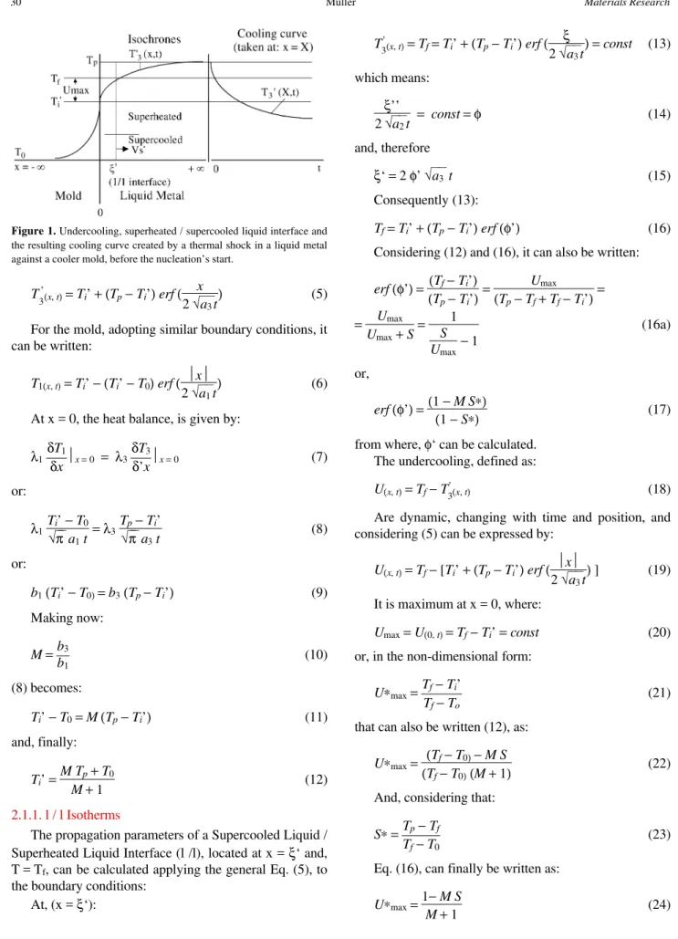
The temperature distribution in the liquid metal and in the mold in a semi-infinite metal-mold system, with an unidirectional heat extraction, without thermal resistance at the metal-mold interface can be calculated through the general solution presented by Schwarz to the problem (Fig. 1):
Tn(,t)=An+Bnerf( x
2 √a3t
) (1)
The constants An and Bn , can be calculated from the boundary conditions:
At, x = 0:
T’ 3(0, t)=A
’
3=Ti’ =const. (2)
At, x = + ∞:
T’
3(+α, t)=Tp=Ti’ +B ’
3 (3)
or:
B’
3=Tp−Ti’ =const. (4)
T’
3(x, t)=Ti’ +(Tp−Ti’)erf(
x
2 √a3t
) (5)
For the mold, adopting similar boundary conditions, it can be written:
T1(x, t)=Ti’ −(Ti’ −T0)erf( x 2 √a1t
) (6)
At x = 0, the heat balance, is given by:
λ1 δT1
δxx= 0 = λ3
δT3
δ’xx= 0 (7)
or:
λ1 Ti’ −T0
√πa1 t =λ3 Tp−Ti’
√πa3 t (8)
or:
b1 (Ti’ −T0)=b3 (Tp−Ti’) (9) Making now:
M=b3
b1 (10)
(8) becomes:
Ti’ −T0 =M(Tp−Ti’) (11)
and, finally:
Ti’ =MTp+T0
M+ 1 (12)
2.1.1. l / l Isotherms
The propagation parameters of a Supercooled Liquid / Superheated Liquid Interface (l /l), located at x = ξ‘ and, T = Tf, can be calculated applying the general Eq. (5), to the boundary conditions:
At, (x = ξ‘):
T’
3(x, t)=Tf=Ti’ +(Tp−Ti’)erf( ξ2 √a 3t
)=const (13)
which means:
ξ’’ 2 √a2t
= const=φ (14)
and, therefore
ξ‘ = 2 φ’ √a3 t (15) Consequently (13):
Tf=Ti’ +(Tp−Ti’)erf(φ’) (16)
Considering (12) and (16), it can also be written:
erf(φ’)= (Tf−Ti’)
(Tp−Ti’)=
Umax
(Tp−Tf+Tf−Ti’)=
= Umax
Umax +S=
1
S Umax− 1
(16a)
or,
erf(φ’)=(1 −MS∗)
(1 −S∗) (17)
from where, φ‘ can be calculated. The undercooling, defined as:
U(x, t)=Tf−T3’(x, t) (18)
Are dynamic, changing with time and position, and considering (5) can be expressed by:
U(x, t)=Tf− [Ti’ +(Tp−Ti’)erf( x
2 √a3t
) ] (19)
It is maximum at x = 0, where:
Umax =U(0, t)=Tf−Ti’ =const (20)
or, in the non-dimensional form:
U∗max =Tf−Ti’
Tf−To (21)
that can also be written (12), as:
U∗max = (Tf−T0)−MS
(Tf−T0)(M+ 1)
(22)
And, considering that:
S∗=Tp−Tf Tf−T0
(23)
Eq. (16), can finally be written as:
U∗max =1−MS
M+ 1 (24)
This development, shows that the Supercooling gener-ated by the collision of two semi-infinite thermal systems without phase transformations, depends exclusively on: the metal’s Superheating Degree (S*), the Initial Mold Tem-perature (T0) and the Heat Extraction Capacity of the metal-mold system (M).
2.2. Second stage: nucleation and growth of the solid
After an incubation time t0 , the nucleation will begin in the undercooled liquid at the places where the supercool-ing is higher.
The liberated latent heat of solidification propagates as a heat wave and will be dissipated in two ways:
1. to the mold, through the undercooled metal that lies between the metal-mold interface and the solidification front;
2. to the undercooled liquid lying in the front of the s / l interface, through the negative gradient that will be cre-ated.
The Solidification parameters have been quantified by the Schwarz , for positive, zero and negative gradients of the liquid, so that one can use his equations1:
The solid phase thickness, varies with time, as:
ξ= 2 φ√a2 t (25)
The temperature distribution in the solid can be ex-pressed by:
T2(X, t)=Ti+Tf−Ti erf(φ)erf(
x
2 √a2t
) (26)
A new metal-mold interface temperature will be estab-lished and expressed by:
Ti=MTf+T0 erf(φ)
M+erf(φ) =const (27)
where, φ, can be obtained solving the following heat balance at the S / L interface:
( S∗ erfc(φ)−
1
M+erf(φ)) exp −(φ
2)+φ√π Lf∗= 0 (28)
where, for this particular case:
S∗=Ti’ −Tf Tf−T0
(29)
The thermal profile of the liquid in front of the S / L interface is given by:
T3(X, t)=Tp− Tp−Tf erfc(φ)erf(
x
2 √a3t
) (30)
2.2.1. Delay and incubation times
Considering that solidification is a two step process, it follows that a cooling curve is the result of the
displace-ment, of the l / l and s / l interfaces, measured by a thermocouple placed in the ingot at a fixed distance X from the metal - mold interface.
The interfaces travel speeds inside the ingot, change with the value of φ‘, φ, which are influenced differently by S*, as can be seen in Figs. 2 and 4.
The l / l interface is the first to reach the thermocouple and it will do it after a time t1 displacing itself, according to:
X= 2 φ’ √a3 t1 (31)
Due to the incubation time (Fig. 3), the s / l interface will come later on, after a time t2, derived from an equation of the type:
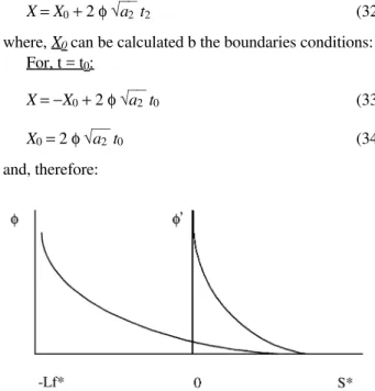
X=X0 + 2 φ√a2 t2 (32)
where, X0 can be calculated b the boundaries conditions: For, t = t0:
X=−X0 + 2 φ√a2t0 (33)
X0 = 2 φ√a2 t0 (34)
and, therefore:
Figure 2. Schematic representation of the variation of φ and φ‘, as a function of S*, for a given metal-mold system. Their behavior is different because they are described by different mathematical expressions.
Figure 3. Influence of the incubation time t0 on the Delay time (t2 - t1)
X= 2 φ√a2 t0 + 2 φ√a2 t2 (35) And if the thermal properties of the liquid and the solid are the same (a2 = a3), and considering that (31) and (35) must be equal, it can be written:
2 φ√a2 √t2 +t0 = 2 φ’ √a3 √t1 (36)
φ√t2 +t0 =φ’ √t1 (37)
φ2(t2 +t
0)=φ’2t1 (38)
t0 =φ
2t2 −φ’2
t1
φ2 (39)
The time difference between the two moments that those interfaces cross the temperature at, T = Tf, and, x =
X, (t1 - t2) can be called delay time and as it has been shown, includes the incubation time t 0 , plus a correction factor proportional to the propagation constants.
2.2.2. Cooling curves
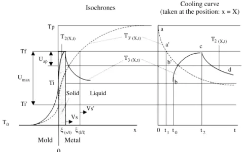
A Cooling Curve of a pure metal can be divided in three segments ab’, b’c and cd that correspond to the Isochrones T’3 (x, t) , T3 (x, t) and T2 (x, t), respectively , that are interrelated together with Ti’, Ti and t 0 , to create the Maximum and the Apparent Undercoolings and the Recalescence (Fig. 4).
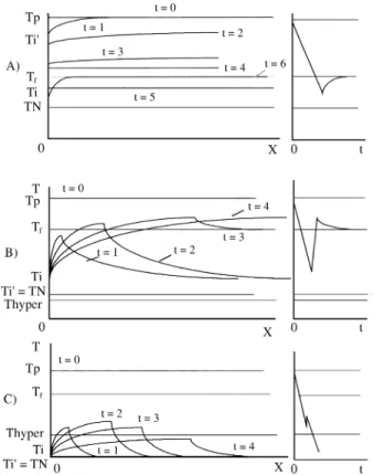
2.2.3. Nucleation Scenarios
Depending on the intensity of the thermal shock (M), the resulting interface temperature (Ti’), can be higher or lower than the melting point (Tf).
i) Ti’ > Tf
In this case there is no thermal shock (U < 0) and the metal will remain liquid after the first contact with the mold. This happens when ingots are produced by a
combi-nation of low heat extraction capacity molds (M > 10: sand molds) and high pouring temperatures.
Semi-infinite ingots, like the Schwarz ones, would not solidify in this condition, but the real ones solidify because the heat flux is not unidirectional.
They loose temperature evenly, introducing all the liq-uid smoothly into the undercooled stage, until the local Nucleation temperature is attained (TN). Because the gra-dients in the liquid are so low, the nucleation chances are quite the same for all points in the casting, and will produce a random Nucleation pattern and an arrest temperature will appear in the cooling curve (Fig. 5a).
The number and size of the crystals so formed will depend on the degree of the local Undercooling, which is normally very low in those cases, because of the nucleation power of the nucleants.
After the nucleation, the temperature will increase from TN to Tf and the growth will proceed in a nearly adiabatic environment, against negative gradients created at every nucleation site, with a velocity given by:
Vad=φad [ a3
t ] 1⁄
2 = 2φ2
ad a3
ξ (41)
where φad can be obtained by making M = infinite, in (21):
φaderf(φad) exp(φad2)=√π Lf∗
U (42)
ii) Ti’ < Tf
In this case, there are two alternatives: Tf > Ti’ > T hyper (Hypocooling):
This condition called Hypocooling in the Literature4, is a consequence of a moderate thermal shock produced by Figure 4. Maximum and apparent undercoolings, superheated / supercooled liquid (l /l), solid / liquid (s / l) interfaces, incubation time (t0) and the resulting
normal metallic molds (M ~ 1), in contact with almost all metals.
The amount of heat extracted at the metal - mold inter-face is not sufficient to produce the critical supercooling (U*hyper), making that the liberated solidification heat will push the temperature to its maximum value4 (Fig. 5b).
The nucleation sites will necessarily be located at the metal-mold interface and growth will proceed over the chilled substrate toward the center of the casting.
Ti’ < T hyper (Hypercooling):
For very high heat extraction power (water cooled molds: M= 0) and with excellent thermal contact, many metals can attain or even surpass the condition, in which amorphous structures can be formed in very thin foils or even in castings (hypercooling4 (see Table 1).
If U*max > U*hyper (Eq. 44), it means that the amount of heat extracted from the liquid by the thermal shock before the beginning of the nucleation, is bigger than the Latent Heat of Solidification that will be released during nuclea-tion, making it impossible to the system to bring the tem-perature back to Tf, during recalescence)4 (Fig. 5c).
This high heat extraction rate, will normally act during very short times at the initial stages of the solidification. With the deterioration of the thermal contact due to cast-ing’s contraction, the heat flux, falls abruptly, giving
Figure 5. Isochrones and resulting cooling curves from three different nucleation scenarios: A) Ti’ > Tf ; B) Tf > Ti’ > Thyper; C) Ti’ < Thyper.
Table 1. Thermal properties and solidification parameters, calculated from Eq. (12) and (20) and (46), for the most common metals (T0 = 293 K).
Metal Tf, (K) Tp, (K) Mold / M Ti’, (K) Umax (K) U hyper(K) Umax / U hyper Remarks
Al 933 993 sand / 25 976 -35 378 - Ti’ > Tf
metal/ 2 759 173 378 0.45 Hypo
w.c. / 0 293 640 378 1.7 Hyper
Au 1336 1373 sand / 25 1331 5 536 0.09
-metal / 2 1013 323 536 0.6 Hypo
w.c. / 0 293 1043 536 1.94 Hyper
Ag 1233 1333 sand / 30 1299 -66 500 - Ti’ > Tf
metal / 2,5 1025 207 500 0.4 Hypo
w.c. / 0 293 940 500 1.88 Hyper
Be 1573 1673 sand / 24 1618 -45 500 - Ti‘ > Tf
metal / 2 1213 360 500 0.72 Hypo
w.c. / 0 293 1280 500 2.56 Hyper
Cr 2103 2273 sand / 12 2120 -17 687 - Ti‘ > Tf
metal / 1 1273 830 687 1.2 Hyper
w.c. / 0 293 1810 687 2.63 Hyper
Co 1768 1923 sand / 15 1821 -53 584 - Ti’ > Tf
metal / 1 1108 650 584 1.1 Hiper
Cu 1356 1493 sand /38 1462 -106 506 - Ti‘ > Tf
metal / 3 1188 168 506 0.33 Hypo
w.c. / 0 293 1063 506 2.1 Hyper
Mg 923 973 sand /16 933 -10 356 - Ti‘ > Tf
metal /1,3 677 245 356 0.7 Hypo
w.c. / 0 293 610 356 1.71 Hyper
Fe 1813 1913 sand / 12 1788 24 590 0.04
-metal/ 1 1103 710 590 1.4 Hyper
w. c. / 0 293 1520 590 2.6 Hyper
Mo 2873 3073 sand /19 2934 -61 1166 - Ti’ > Tf
metal /1,5 1961 912 1166 0.78 hypo
w.c. / 0 293 2580 1166 2.21 Hyper
Ni 1728 1923 sand /18 1837 -109 740 - Ti’ > Tf
metal/ 1,4 1243 484 740 0.65 Hypo
w.c. / 0 293 1435 740 1.94 Hyper
Pb 600 653 sand / 7 607 -7 210 - Ti’ > Tf
metal /0,5 413 187 210 0.9 Hypo
w.c. / 0 293 307 210 1.46 Hyper
Pd 1827 2023 sand /12 1889 -63 570 - Ti’ > Tf
metal / 1 1158 669 570 1.17 Hyper
w.c. / 0 293 1534 570 2.7 Hyper
Pt 2046 2273 sand /12 2120 -74 900 0.18 Ti’ > Tf
metal / 1273 773 900 0.86 Hypo
w.c. / 0 293 1753 900 1.94 Hyper
Sb 1439 1523 sand /20 1463 -25 766 - Ti’ > Tf
metal /1,8 1083 355 766 0.46 Hypo
w.c. / 0 293 1146 766 1.5 Hyper
Sn 505 550 sand / 12 530 20 290 0.07
-metal /0.8 407 143 290 0.5 Hypo
w.c. / 0 293 277 290 0.95 Hypo
Si 1603 1803 sand /11 1677 26 2106 0.012
-metal / 1 1048 655 2106 0.32 Hypo
w.c. / 0 293 1410 2106 0.67 Hypo
W 3683 3973 sand /22 3813 -130 1466 - Ti’ > Tf
metal /1,8 2658 1024 1466 0.7 Hypo
w.c. / 0 293 2390 1466 2.0 Hyper
Zn 692 773 sand /17 746 -54 266 - Ti’ > Tf
metal /1,4 573 119 266 0.44 Hypo
w.c. / 0 293 399 266 1.5 Hyper
chance for a new structure to grow over the amorphous / chilled substrate.
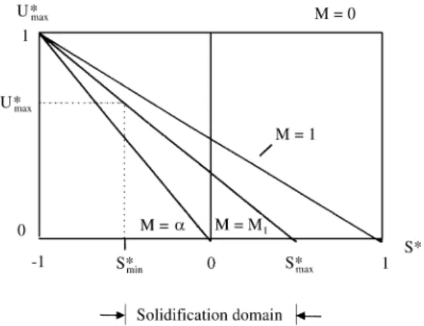
2.2.4. Solidification domain
In Fig. 6, there is a representation of Eq. (24), showing that U*max decreases with the increase in the Superheating Degree (S*), for various Heat Extraction Capacities of the Metal-Mold System (M).
For a perfectly adiabatic mold (M = infinite), there is no thermal shock and (U*max > 0), only if the metal is poured in a undercooled state (S* < 0).
In the case where the metal and the mold are of the same material (M = 1), those values change, making, U*max = 0, when S* = 1 and U*max = 1, for S* = -1.
In the particular case of a water-cooled mold (M= 0), the supercooling generated by a thermal shock will always be U*max = 1, independently of the S* values.
One can now consider that those two limit values of S*
(S*max and S*min), create a ‘‘Solidification Domain’’, whose limits can be determined by:
S*max, that is the maximum superheating degree that will produce a positive undercooling, by simply contacting with a Mold (thermal shock), and, S*min, that corresponds to the minimum value of superheating that will produce a crystalline structure, avoiding an amorphous solidification, that happens when U* = U*hyper (from hypercooling).
If the metal is poured with S*max > 1, in a metallic mold (M = 1), the resulting Supercooling at the metal-mold interface will be negative (U*max < 0), or in other words no undercooling, but a residual superheating will exist (Ti’ > Tf).
On the other hand, the U*hyper value that can be achieved with different combinations of S* and M.
The Solidification Domain Limits can be calculated through the following expressions:
First, to have nucleation, it is necessary that:
U > 0
than, considering that the most probable place to occur is at the metal/mold interface, it can be written, taking in account (24):
U∗max =1−MS
M+ 1 > 0 (43)
from which:
S∗max ≤ 1
M (44)
or, the maximum pouring temperature, is (18) (20):
Tpmax =Tf+Tf−T0
M (45)
The lower limit, is established considering the maxi-mum Undercooling value that will produce a crystalline structure, which is:
Umax =Uhyper=Tf−Tphyper= Lf
Cp (46)
or,
Tphyper ≤ Tf− Lf
Cp (47)
3. Results and Discussion
In Table 1, the solidification parameters calculated for 18 pure metals solidifying in three different molds (sand / refractory material, iron mold and water-cooled copper mold), at T0 = 293 K, poured with superheating degrees similar to the normal practice, are presented.
The results show that it is possible to obtain negative and positive values of U*max, for most of them, depending on the superheating degree and mold type.
Negative U*max values, were associated with sand molds, while moderately positive to metallic molds and very positive, to water-cooled ones.
From those data, the following ranking of metals prone to solidify extensively in sand molds under thermal shock, can be established:
W, Ni, Cu, Pt, Ag, Pd, Mo, Co, Zn, Be, Al, Sb, Cr, Mg, Pb.
In opposition, Si, Fe and Au, have the tendency to solidify progressively, in the same conditions.
The tendency to hypercooling solidification has been estimated by the relation U*max / U*hyper, giving the follow-ing sequence:
Pd; Fe and Cr; Co and Be; Mo; W, Cu and Ni; Pt and Ag; Mg, Al and Au; Zn and Sb; Pb; Si.
melting point, change with the position of the thermocou-ples. Close to the metal/mold interface, those parameters practically ‘‘vanish’’, confirming the previsions made in the MSModel, for pure metals.
Bäckerud and Chalmers8, working with Al-4Cu alloy found the following evidences that are in good agreement with the presented Model:
- ‘‘the arrest temperatures decreased with the increase of the heat extraction;
- the total melt was undercooled before the initial nu-cleation occurred at the inner mold surface;
- a thin layer of solid formed near the mold walls and the latent heat rises the temperature of this region above that of the melt in the interior;
- latent heat was conducted from the surface layer toward the center of the casting;
- after a certain time (around 11 s), the temperature gradient, was zero throughout the entire sample and from that moment the heat extracted through the mold wall, completely determined the growth rate and the temperature gradients inside the casting;
- the temperature constancy at the center, indicated that the pool of liquid was during this time, surrounded by an isothermal surface that remained at a temperature that did not change, unless the heat extraction rate was changed’’.
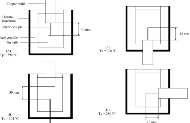
To test some of the ideas of this model, some prelimi-nary experiments were conducted with commercially pure Tin (Tp ~ 300 °C), based in the ‘‘cold-finger’’ type metal-mold system that can be seen in Fig. 79.
A copper mold (250 mm long x 25,4mm diameter, pure copper rod), was placed in three different positions and the liquid metal was held in a steel crucible, (T0 = 20 °C), (60
φ x 50 φ x 150 mm), covered inside with a thermal insulat-ing white paintinsulat-ing and wrapped with 3 layers of ceramic wool.
The cooling curves were taken by Chromel-Alumel thermocouples at different distances from the metal-mold interface, and recorded by a computerized system.
Figure 8, shows the cooling curves corresponding to thermocouples placed at 30 and 40 mm, from the metal / mold interface. Both present, a ‘‘recalescence’’ in which the temperature reaches values bigger than the melting point, before reaching the arrest temperature, as predicted by Herlach4.
In Fig. 9, with thermocouples placed at 15 mm from the metal-mold interface, it can be seen a similar effect, but without ‘‘arrest temperature’’, probably because the system was still semi-infinite during the time of measurements.
Those experiments that are preliminary, should be fur-ther enlarged, because they show simultaneously the natu-ral convection effect on the resulting cooling curves.
4. Conclusions
The utilization of the MS Model to the description of the solidification process of pure metals, brought some new ideas and concepts, that can be put as conclusions:
1. The solidification process generates two heat fronts inside the castings : the Supercooled / Superheated Liquid (l / l) and the Solid / Liquid (s / l) Interfaces, separated by a nucleation time and moving with different velocities;
2. The thermal shock, is a very important parameter to make predictions of the solidification modes of metals and alloys;
3. Theoretically, taking in account only thermal aspects, Hypercooling can easily be attained in almost all metals, when they solidify with a perfect metal / mold contact, against copper cooled molds at room temperature;
4. It was possible to evaluate the hypercooling prone-ness of pure metals;
5. In many practical cases, the solidification of finite ingots in sand molds, will begin with Tí > Tliq, followed by a nucleation in a liquid under near zero gradient;
6. It is possible, using a same mold, to change the solidification mode of metals, by adjusting its pouring temperature, or, for a same pouring temperature, by chang-ing the material and or temperature of the mold;
7. The incubation time, can be theoretically estimated from measurements taken in normal cooling curves.
References
1. Schwarz, C. Arch. Für Eisenhüttwesen, H. 3, p. 139-148, Sept 1931.
2. Müller, A. Proc. 49th. Congress of the Brazilian Met-allurgical and Materials Society (ABM), São Paulo, p., 343-352, 1994.
3. Müller, A. Proc. 61st World Foundry Congress, Bei-jing, p. 51-61, 1995.
4. Herlach, D.M. Mat. Sci. Eng., R. 12, n. 4-5, p. 177-272, Aug. 1994.
Figure 9. Idem, for molds and thermocouples placed as in Fig. 8 C, D. The recalescences appeared again, without clear arrest temperatures, which can happen when the systems are truly semi-infinte9.
5. Biloni, H. Aluminum Transformation Technology and Applications, ASM, Metals Park, OH, pg. 1, 1979. 6. Kisukurek, S.E. Journal of Mat. Sc. n. 19, p.
2289-2305, 1984.
7. Gandin, Ch.-A.; Rappaz, M. Acta Metall. Mater., v. 42, n. 7, p. 2233-2246, 1994.
8. Bäckerud, L. and Chalmers, B., Trans. of the Metall. Soc. of AIME, v. 345, feb. 1969, p 309-318.
9. Müller, A. To be published.
List of Symbols
a = thermal diffusivity b = heat diffusivity Cp = specific heat erf = error function
erfc = complementary error function = (1 -- erf) l = liquid
l / l = superheated liquid / supercooled liquid interface Lf = latent heat of solidification
M = metal / mold constant = b2 / b1 ,or , b3 / b1 s = solid
s / l = solid / liquid S = Superheating degree T = Temperature U = Undercooling t = time
x = distance from the metal / mold interface
X = thermocouple distance from the metal/mold inter-face
λ = thermal conductivity coefficient
φ = Schwarz constant
ξ = coordinate of the s / l interface
ξ’ = coordinate of the supercooled / superheated inter-face
List of Indexes
0 = initial 1 = mould 2 = solid metal 3 = liquid metal ad = adiabatic f = fusion
hyper = hypercooling hypo = hypocooling i = metal / mold interface Liq = Liquidus