THE ROLE OF HYBRID NANOFLUIDS
IN IMPROVING THE THERMAL CHARACTERISTICS
OF SCREEN MESH CYLINDRICAL HEAT PIPES
by
Raghavan Nair RAMACHANDRANa*, Kalliappan GANESANb,
and Lazarus Godson ASIRVATHAMc
a
Anna University, Chennai, India
b
Department of Mechanical Engineering, PSG College of Technology, Coimbatore, India
c
Department of Mechanical Engineering, Karunya University, Coimbatore, India
Original scientific paper DOI: 10.2298/TSCI150710006R
Experiments were conducted to study the thermal performance of meshed wick heat pipe by varying the working fluid and heat input. In this work four screen mesh wicked heat pipes were fabricated and tested. All the heat pipes were tested for heat input from 50 W to 250 W each with an increment of 50 W in each step. The heat input range selected in this study is commonly encountered in most of the electronic application devices. The thermal resistance of all the heat pipes charged with different working fluids such as de-ionised water, Al2O3/de-ionised water nanofluid of volume concentration 0.1%, and hybrid nanofluid volume concentration 0.1%, with two different combinations of (Al2O3 50%-CuO 50%)/de-ionised water and (Al2O3 25%-CuO 75%)/de-ionised water, was deter-mined. The maximum percentage reduction was found to be 58.87% for the hy-brid nanofluid of (Al2O3 25%-CuO 75%)/de-ionised water compared to base flu-id. An important observation from the study is that, use of hybrid nanofluid can raise the operating range of the heat pipe beyond 250 W which makes hybrid nanofluid as a potential substitute for the conventional working fluid.
Key words: screen mesh heat pipe, hybrid nanofluid, thermal resistance, effective thermal conductivity
Introduction
Over the last decade, due to advancement in electronic industry, it is possible to pro-duce high performance integrated electronic devices. These devices are subjected to high heat flux and therefore their thermal management has become very serious concern for many re-searchers. Among the different cooling methods, the role of heat pipe as an effective cooling device has recently become very interesting area of research because of their high thermal con-ductivity, reliability, and low weight penalty, etc. These features make them useful in many electronic and computer systems [1-5]. Even though there are many factors [6-13] which affect the performance of heat pipe, role of working fluid is very important, since the heat pipe utilise the phase change phenomena of the working fluid for the transport of heat. Different working fluids has been tried by many researchers, however, recently application of nanofluids as work-ing fluid in heat pipes has been a subject of interest due to the unprecedented thermal
character-––––––––––––––
Ag-H2O and Al2O3-H2O. It was proved that the present hybrid working system, pure nanoparti-cle fluid system was better than hybrid nanofluids system. Even though there is literature per-taining to this area, more research needs to be done because the combinations and volume con-centration of different nanoparticles can affect the performance characteristics of many heat transfer equipment, especially heat pipes. In the present study, experiments have been conduct-ed to evaluate the feasibility of using two different combinations of Al2O3-CuO hybrid nanoflu-ids in cylindrical mesh wicked heat pipes and compare its thermal performance with DI water and Al2O3/DI water nanofluid.
Experimentation
Preparation of nanofluid
The first key step in the experimental work is the preparation of nanofluid. In the pre-sent investigation, two types of nanoparticles, such as Al2O3 and hybrid nanoparticle (a combi-nation of Al2O3-CuO) are used with DI water as the base fluid. The Al2O3/DI water nanofluid contains commercial nanoparticles manufactured by Alfa Aesar USA (Product number 44931 of 40-50 nm). The density of Al2O3 nanoparticle is approximately 3950 kg/m
3
. The crystalline phase of Al2O3 nanoparticles was determined by X-ray diffraction, (XRD) using Shimazdu Labx-6000. The XRD image depicted in fig. 1
shows the crystalline nature of the Al2O3 particle. The average crystalline size of nano-particle was calculated using the Scherrer for-mula [23] stated in eq. (1):
cos K
D λ
β θ
= (1)
where D is the crystalline size, K – the shape factor with a value of 0.9-1.2, λ – the wave-length of X-ray, (1.54056 Ao), θ – the Braggs angle, and β– the value of full width at half maximum (at radian). The full width half maximum corresponding to peak values of in-tensity at different 2θ is obtained from the XRD pattern. Based on the calculation, the average size of Al2O3 was found to be 14.38 nm. The hybrid nanofluid Al2O3-CuO/DI wa-ter contains Al2O3 and CuO nanoparticles. The CuO nanoparticles are manufactured by Sky-spring Nanomaterials Inc., Houston, Tex., USA (Product No. 2810-071814). The XRD pattern depicted in fig. 2 shows the crystalline nature of CuO nanoparticle. The average par-ticle size of CuO nanoparpar-ticles was found out from the results of the XRD test based on the same procedure described for Al2O3 and the average particle size was found to be 17.36 nm.
Figure 1. The XRD pattern of Al2O3 nanoparticles
The hybrid nanofluid was prepared by a combination of Al2O3 and CuO of volume concentration 0.1% mixed with DI water and sonicated for one hour in an ultrasonic cell dis-ruptor (Model KS500F). Two different combinations of hybrid nanofluid such as, Al2O3 50%-CuO 50%, and Al2O3 25%-CuO 75%was used for the study.
Experimental set-up
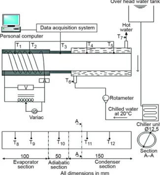
Figure 3 shows the schematic of the experimental set-up. The heat pipes were fabricat-ed with commercially available straight Cu tubes with outer diameter of 12.5 mm, inner diameter
11.5 mm, with a length 300 mm. The evaporator, adiabatic, and condenser sections were maintained at a length of 100 mm, 50 mm, and 150 mm, respec-tively. Screen mesh made of Cu was used for the construction of the heat pipe wick. Three layers of 100 mesh screen Cu wick are scrolled into the inner surface of the tube and tightly af-fixed by a spring mechanism. The wick is completely saturated by filling the heat pipe with 5.12 ml of different working fluids at 13.46 KPa. Both ends of the Cu tube were closed by end caps. A constant heat input is giv-en to the evaporator by a 300 W Ni-chrome wire heater wound circumfer-entially on the outer surface of the evaporator.
The power supply to the electric heater is controlled by an auto trans-former and the power input is meas-ured by a digital multimeter. A 220 W, 50 Hz AC supply is given as input to the circuit. The condenser section was covered by an acrylic tube with 35 mm diameter and is cooled by water. The inlet coolant temperature is maintained at a specified value of 20°C by constant temperature bath (chiller unit) with a flow rate of 12 liter per hour (LPH). The evaporator region and the adiabatic regions are perfectly insulated with glass wool to minimize the heat loss between the heat pipe and the surroundings. Ten T-types thermo-couples employed at different locations of the heat pipe were used for measuring the temperature. Among these ten thermo-couples five were placed at the surface of the heat pipe and remaining five inside the heat pipe (vapour core) at different locations i. e. two at evaporator, one at adiabatic, and two at condenser region to measure the surface and vapour temperature. The thermo-couples located at the surface of the heat pipe are welded to measuring points and fixed using highly conducting thermo-bond. Additional two thermo-couples were also placed at the inlet and outlet of the cooling water jacket in the condenser region. The lead wires of all the thermo-couples are con-nected to computer based data acquisition system (Agilent India Ltd.).
The whole assembly is fabricated as shown in fig. 4. Since experiments were conduct-ed for DI water, Al2O3/DI water nanofluid and two hybrid nanoparticle/DI water, four different
heat pipes were fabricated for this purpose. The orientation for all the heat pipes was kept hori-zontal throughout the experiment. The heat pipe was kept in operation for sufficient period of time till the temperature recorded by the thermo-couples showed a steady value.
Data reduction
An important performance parameter which defines its performance under the given
heat load conditions is its thermal resistance [24], defined in eq. (3).
Q=V I (2)
,wall ,wall E C HP T T R Q − = (3) eff c HP L k A R = (4)
The experimental uncertainty
In this work the dependent parameter are heat flux, thermal resistance and effective thermal conductivity. These parameters are dependent upon voltage, V, current, I, length of the evaporator, L, diameter of evaporator, d, and the temperature difference between the evaporator and condenser. The
uncertainty in the dependent pa-rameter is estimated by using eq. (5), wherein, σR is the
uncer-tainty in the estimation of the dependent parameter R, and σXi
is the uncertainty associated
with independent parameter X. The detailed procedure for estimating the uncertainty is out-lined in [25]. The uncertainty in the independent parameter can be obtained either from the calibration of the instrument or it will be specified by the manufacturer. The uncertainty in the independent (measured) parameter and the dependent parameters is reported in tab. 1.
2 2 1 n R Xi i i R X σ σ = ∂ = ± ∂
∑
(5)Results and discussions
Four different heat pipes with different heat inputs (50-250 W in steps of 50 W) were used for the present experimental study. Various working fluids namely, DI water, Al2O3/DI water of 0.1 % volume concentration, and (Al2O3 + CuO)/DI water hybrid nanofluid of 0.1% volume concentrations were used for the experimental study. Two combinations of hybrid nanofluids Al2O3 50%-CuO 50% and Al2O3 25%-CuO 75% with total volume concen-tration of 0.1 vol.% were used for the experiments.
Figure 4. Photograph of experimental set-up
Table 1. Uncertainty of the measured and estimated parameters
Parameters L [mm] V [V] I [A] T [°C] Q [%] RHP [%] keff [%]
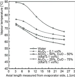
Distribution of vapour temperature along the axial length of the heat pipe plotted in fig. 5, which reveals that by using nanofluids, the vapour temperature in the heat pipe de-creases due to high thermal conductivity of nanoparticles. It is observed that the average va-pour temperature in the evaporator of the heat pipe drops by 16.89 °C for Al2O3 25%-CuO 75% hybrid nanofluid, compared with DI water. A significant drop in temperature is also ob-served in the condenser which is circulated with cooling water maintained at constant temper-ature. This significant drop in temperature in the evaporator for a constant heat input indicates the ability of the heat pipe to operate under higher heat loads when compared to that of the base fluid heat pipe.
An important parameter which affects the performance of the heat pipe is the adia-batic vapour temperature which is otherwise known as the operating temperature of the heat pipe. It can be inferred from fig. 6 that the operating temperature increases with increase in heat load and decreases as the total weight of nanoparticle in the base fluid increases. It is worth mentioning here that while using hybrid nanofluid the total quantity of nanoparticle in-creases which in turn inin-creases the total weight of the nanofluid as depicted in tab. 2. The re-duction in temperature due to the increased weight of the nanoparticle indicates ability of the heat pipe to have high heat transfer capability. An 21.39% reduction is observed in case of heat pipe operating with Al2O3 25%-CuO 75% at the heat load of 250 W.
Figure 5. Distribution of vapour temperature along the axial length (Q = 200 W)
Figure 6. Variation of adiabatic vapour temperature as a function of heat load
It is important to note from fig. 6 the presence of hybrid nanofluid increases the op-erating temperature range of the heat pipe beyond 250 W which is the maximum heat load in the case of the present DI water based heat pipe.
Table. 2 Mass of nanoparticle required to prepare 50 ml nanofluid (total vol 0.1%)
Working fluid Al2O3 [mg] CuO [mg] Total [mg]
Al2O3/DI water 198 – 198
(Al2O3 50%-CuO 50%)/ DI water 99 153 252
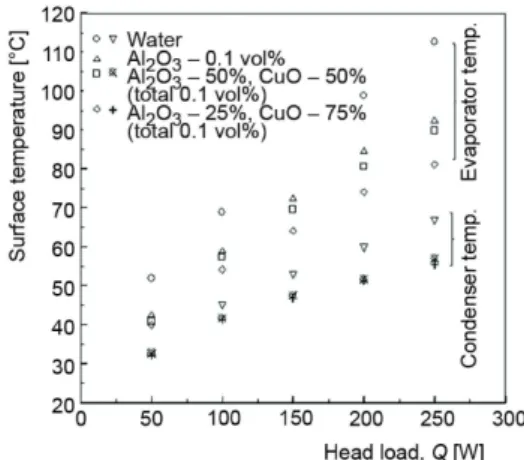
Figure 7 shows the variation in surface tem-perature in evaporator and condenser with various heat loads. The evaporator surface temperature in-creases with heat load and dein-creases with increase in the total weight of nanoparticle in the base fluid increases. This reduction in surface temperature enhances and aids the faster cooling rate of the heat pipe. It is seen that for the hybrid nanofluid of Al2O3 25%-CuO 75% the decrease in the evap-orator surface temperature is about 31.49 °C for a heat input of 250 W. Similarly the evaporator sur-face temperature of heat pipe with hybrid nanoflu-id of Al2O3 50%-CuO 50%, Al2O3/DI water is re-duced by 22.85 °C, 20.3 °C when compared with heat pipe using DI water. The lowering of evapo-rator surface temperature with increase in the total weight of nanoparticle permits the heat pipes to withstand higher heat loads before reaching dry-out condition.
Figure 8 shows the vapour temperature dif-ference between the evaporator and condenser as a function of heat load. For a given heat load the temperature difference between the evaporator and condenser gradually decreases with increase in the total weight of the nanoparticles. This clear-ly shows that it is possible to operate the heat pipe under larger heat loads by using hybrid nanofluids with more nanoparticles. It can also be inferred that the temperature difference reduces by 51.33%, 47.2%, 35.82%, respectively, for Al2O3 25%-CuO 75% hybrid nanofluid, Al2O3 50%-CuO 50% hybrid nanofluid, and Al2O3 nanofluid when compared to the heat pipe operating with DI water at a heat load of 250 W. This conveys that the heat transport capability of the heat pipe working with
Al2O3 25%-CuO 75% hybrid nanofluid is better. The reason for reduction in temperature differ-ence is due to the deposition of nanoparticles in the screen mesh wick of the evaporator, which forms a porous coating. This porous coating, allows the liquid molecules to get strongly attract-ed to the solid nanoparticles depositattract-ed in the evaporator section, eventually rattract-educing the contact angle at the liquid solid interface. This reduction in contact angle leads to increase in surface wettability and surface roughness. Apart from this the porous coating has a capillary effect, due which more liquid will be drawn from the condenser to the evaporator. All these factors along with increased evaporator surface area leads to greater reduction in temperature differences. Stated differently, larger reduction in temperature difference causes higher heat transfer rate.
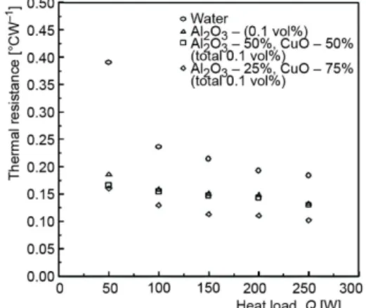
As seen in fig. 9, the thermal resistance of the heat pipe using the base fluid, nanofluid, and hybrid nanofluids is higher at low heat loads, because of the formation of a thin liquid film in the evaporator section. However, as the heat load increases the thermal
Figure 7. Evaporator and condenser surface temperature as a function of heat load
resistance decreases. The reduction in thermal resistance is found to be more while using a hy-brid nanofluid compared to heat pipe operating with pure nanofluid and DI water. An 52.36% reduction in thermal resistance is observed for Al2O3 nanofluid compared to that of DI water. Furthermore, it is also seen that a maximum re-duction in thermal resistance of about 58.87% is observed in the case of hybrid nanofluid with Al2O3 25%-CuO 75% compared to that of DI water. As the total weight of nanoparticle in-creases, the thickness of the porous layer coat-ing also increases which in turn significantly re-duces the thermal resistance of the heat pipe.
As stated earlier a heat pipe employing nanofluid as the working substance has the abil-ity to transfer more heat. This point is further es-tablished from the plot of the effective thermal conductivity vs. heat load depicted in fig. 10. It can be inferred from the figure that the effective thermal conductivity of the heat pipe increases by 38.34% for Al2O3/DI water, 41.47% for (Al2O3 50%-CuO 50%)/DI water, and 79.35% for (Al2O3 25%-CuO 75%)/DI water compared to the base fluid (DI water) for the maximum heat load considered in this study.
Conclusion
Experiments have been conducted to inves-tigate the performance of heat pipes using vari-ous working fluids such as, DI water, Al2O3/DI water nanofluid, and (Al2O3 50%-CuO 50%)/DI water hybrid nanofluid and (Al2O3 25%-CuO 75%)/DI water hybrid nanofluid. It can be seen from the study that the operating temperature of the heat pipe is inversely proportional to the total weight of hybrid nanoparticle in the base fluid and therefore hybrid nanofluid can increase the operating range of heat pipe above 250 W. Experimental results also showed that the thermal resistance of the heat pipe decreases with the use of hybrid nanofluid which in turn increases its effective thermal conductivity by 38.34% for Al2O3/DI water, 41.47% for (Al2O3 50%-CuO 50%)/DI water, and 79.35% for (Al2O3 25%-CuO 75%)/DI water compared base fluid (DI water) for the maximum heat load considered in this study.
Nomenclature
Ac – area of cross section, [mm2]
D – crystalline size, [nm] d – diameter, [mm] I – current, [A] K – shape factor
keff – effective thermal conductivity, [Wm–1K–1]
L – length of the heat pipe, [mm] Q – heat load, [W]
RHP – thermal resistance, [°CW–1] C
T – average condenser surface temperature, [°C]
E
T – average evaporator surface temperature, [°C] V – voltage [V]
Figure 9. Thermal resistance as a function of heat load
Greek symbols
β – full width at half maximum [radians]
θ – Braggs angle
λ – wave length of X-ray [Ao]
Reference
[1] Oomi, M., et al., A Heat Pipe System for Cooling a Desktop Computer, Adv. Electron. Packaging, 2 (1999), pp. 1951-1955
[2] Lin, L., et al., High Performance Miniature Heat Pipe, Int. J. Heat Mass Tran.,45 (2002) 15, pp. 3131-3142 [3] Vasiliev, L. L., Micro and Miniature Heat Pipes-Electronic Component Cooler, Appl. Therm. Eng., 28
(2008), 4, pp. 266-273
[4] Sonan, R., et al., Transient Thermal and Hydrodynamic Model of Flat Heat Pipe for the Cooling of Elec-tronic Components. Int. J. Heat Mass Transfer 51 (2008), 25, pp. 6006-6017
[5] Brautsch, A., Kew, P. A., Examination and Visualisation of Heat Transfer Processes during Evaporation in Capillary Porous Structures. Appl . Therm. Eng., 22 (2002), 7, pp. 815-824
[6] Ma, H. B., et al., Effect of Nanofluid on the Heat Transport Capacity in an Oscillating Heat Pipe. Ap-plied Physics Letters, 88 (2006), 14, ID 143116
[7] Xu, J., et al., Effect of Pore Parameters on Thermal Conductivity of Sintered LHP Wicks. Int. J. Heat Mass Transfer, 55 (2012), 9, pp. 2703-2706
[8] Semena, M. G., Zaripov, V. K., Influence of the Diameter and Length of Fibres on Material Heat Trans-fer of Metal Fibre Wicks of Heat Pipes, Therm. Eng., 24 (1977), 4, pp. 69-72
[9] Lee.,Y., Bedrossian, A., The Characteristics of Heat Exchangers using Heat Pipes or Thermosyphon, Int. J. of Heat and Mass Transfer, 21 (1978), 2, pp. 221-229
[10]Tsai, C. Y., et al., Effect of Structural Character of Gold Nanoparticles in Nanofluid on Heat Pipe Ther-mal Performance, Material Letters, 58 (2004), 9, pp. 1461-1465
[11]Thuchayapong, N., et al., Effect of Capillary Pressure on Performance of a Heat Pipe: Numerical ap-proach with FEM, Appl. Therm. Eng., 32 (2012), Jan., pp. 93-99
[12]Lips, S., Lefevre, F., A General Analytical Model for the Design of Conventional Heat Pipes Int. J. of Heat and Mass Transfer,72 (2014), May, pp. 288-298
[13]Suman, B., Kumar, P., An Analytical Model for Fluid Flow and Heat Transfer in a Micro Heat Pipe of Polygonal Shape, Int. J. Heat Mass Transfer,48 (2005), 21-22, pp. 4498-4509
[14]Do, H., et al., Thermal Resistance of Screen Mesh Heat Pipes using the Water Based Al2O3 Nanofluids,
Int. J. of Heat and Mass Transfer,53 (2010), 25-26, pp. 5888-5894
[15]Shafahi, M., et al., An Investigation of the Thermal Performance of Cylindrical Heat Pipes Using Nanofluids, Int. J. of Heat and Mass Transfer,53 (2010), 1-3, pp. 376-383
[16]Putra, N., et al., Thermal Performance of Screen Mesh Wick Heat Pipes with Nanofluids, Experimental Thermal and Fluid Sciences, 40 (2012), July, pp. 10-17
[17]Hung, Y. H., et al., Evaluation of the Thermal Performance of a Heat Pipe Using Alumina Nanofluids, Experimental Thermal and Fluid Sciences,44 (2013), Jan., pp. 504-511
[18]Kumaresan, G., et al., Experimental Investigation on Enhancement in Thermal Characteristics of Sintered Wick Heat Pipe Using CuO Nanofluids. Int. J. of Heat and Mass Tran.,72 (2014), May, pp. 507-516 [19]Kole, M., Dey, T. K., Thermal Performance of Screen Mesh Wick Heat Pipes Using Water-Based
Cop-per Nanofluids, Appl . Therm. Eng., 50 (2013), 1, pp. 763-770
[20]Suresh, S., et al., Effect of Al2O3-Cu/Water Hybrid Nanofluid in Heat Transfer, Experimental Thermal
and Fluid Science, 38 (2012), Apr., pp. 54-60
[21]Han, W. S., Rhi, S. H., Thermal Characteristics of Grooved Heat Pipe with Hybrid Nanofluids, Thermal Science, 15 (2011), 1, pp. 195-206
[22]Jena, P. K., et al., Identification of a Third Phase in Cu-Al2O3 Nanoscale Composites Prepared by
Chem-ical Routes, Material Science and Engineering: A, 371 (2004), 1-2, pp. 72-78
[23]Kwon, Y. J., et al., Characterization of ZnO Nanopowders Synthesized by the Polymerized Complex Method via an Organochemical Route, Journal of Ceramic Processing Research, 3 (2002), 3, pp. 146-149 [24]Reay, D. A., et al., Heat Pipes, Theory, Design and Applications, Elsevier, New York, USA, 2014 [25]Kline, S. J., Mcklintock, F. A., Describing the Uncertainties in Simple Sample Experiments, Mech. Eng.,
75 (1953), 1, pp. 3-8