Microstructural behavior of SAF 2205 Duplex Stainless Steel Welded by Friction Hydro
Pillar Processing
Cleber Rodrigo de Lima Lessaa*, Douglas Martinazzib, Arlan Pacheco Figueiredoa, Rodrigo Batista
Machadob, Claudia Fanezib, Telmo Strohaeckerb
aInstituto Federal do Rio Grande do Sul – IFRS, Caxias do Sul, 95043-700, Rio Grande do Sul – RS,
Brazil
bDepartamento de Metalurgia – DEMET, Universidade Federal do Rio Grande do Sul –UFRGS,
90035-190, Porto Alegre, RS, Brazil
Received: January, 14, 2016; Revised: May, 07, 2016; Accepted: June, 24, 2016
The Friction Hydro-Pillar Process (FHPP) is an innovative process that has been recently studied regarding its possible in situ repair applications. There is still no literature about usage of the FHPP on duplex stainless steel (DSS) base materials to smaller forces than 25 kN. The investigation on DSS processing is crucial due his wide variety of critical uses in pipes and storage structures applied in chemical industry plants, where usual welding processes may lead to safety concerns. The aim of this study is to qualify the processing of SAF 2205 (UNS 31803) duplex stainless steel welded joints using FHPP as feasible repair procedure. For this, the studied samples were welded applying a range of axial forces. The welded joints were characterized by, α/γ phase ratio, intermetallic quantiication, austenite spacing measurement, microhardness proile and microstructural qualitative studies. The results showed the eiciency in repair of the FHPP process on the production of DSS joints according with the material recommendations from the standard DNV-RP-F112.
Keywords: Friction Hydro Pillar Processing; Duplex stainless steel; Repair; Microstructure
1. Introduction
The duplex stainless steels (DSSs), characterized by ferrite-austenite dual phase microstructures, are widely used in petrochemical, oil, chemical, nuclear and marine industries because of their combination of high mechanical strength and good corrosion resistance in aggressive environments1.
The SAF 2205 may be referred as the most extensively DSS used nowadays, constituting approximately 80% of its total amount consumed2. However, due to high chromium (~22%Cr)
and molybdenum (~3%Mo) contents and their high difusion rate in ferrite, DSSs present a tendency to form unwanted secondary phases during exposure to temperatures between 400 and 1000 ºC3,4. Besides, thermal processes that involve
long exposition periods of DSS to high temperature, may aggravate the appearance of Mo-enriched χ phase3,5. The
high degree of χ phase precipitation is also associated to negative efects on corrosion and mechanical properties6,7.
In industrial plants it is common to have the requirement of maintenance intervention due to safety regulation. Normally, conventional arc welding processes are employed in cases where structure repairs are needed. The concept of illing weld repair of localized damage process which allow fast, eicient and cost-efective led to the design of Friction Hydro Pillar Processing (FHPP)6,8–10macrostructure and
mechanical properties in AISI 4140 steel. It also presents 3D residual stress data for a typical friction taper stud weld. Applied downwards force, rotational speed and plunge depth (equivalent to consumable length. The FHPP was initially developed by specialists at TWI (The Welding Institute)
aiming to create a safer and more eicient technique weld joints production and localized damage repairing in metallic structures11. The process involves irstly the machining a
hole in order to remove the region containing a previous detrimental discontinuity followed by co-axial rotation a consumable plug under controlled load generating frictional heat which continuously produces a plasticized layer responsible for the complete hole illing8,12 (Figure 1 and
Figure 2). This process occur in the materials in solid state, promoting then less microstructural alteration and lower residual stress levels than conventional arc welding, which depends upon the materials fusion and solidiication. Hence, the result of having minor microestructural modiications in base materials is the possibility of using this welding process in situ, i.e., without the necessity of any requirement of plant shutdown in order to repair a single or group of components. Consequently, FHPP welds may ofer considerable time, energy and cost savings over fusion welding in repairs applications10 macrostructure and mechanical properties in
AISI 4140 steel. It also presents 3D residual stress data for a typical friction taper stud weld. Applied downwards force, rotational speed and plunge depth (equivalent to consumable length. Further research on the FHPP technique extended its potential applications to crack repair11,13, hole illing9,14,
cladding and material processing8. Due to this processing
adaptable quality, further works showed its applicability in diferent materials such as low carbon steels with diferent axial forces, 50, 200, 250, 300, 350 and 400 kN8,9,15,16.
Pinheiro joined diferent magnesium (Mg) materials using FHPP17. This process was used on the repair of undersea
structures, including oil pipelines18–20. It was already studied
Figure 1: Schematic illustration showing FHPP process. a) Rotating consumable plug co-axially, b) processing and pressed against structure.
Figure 2: FHPP Processing. a) Rotating consumable plug co-axially, b) processing and pressed against structure.
kN which resulted joint with good toughness21. The FHPP
can be automated6 and distance operated ensuring greater
reproducibility19. This process may presents few disadvantages
as lack of bond, incompletely illed groove and a complex mechanical and metallurgical characterization9.
The aim of this study is to qualify the processing of SAF 2205 (UNS 31803) duplex stainless steel welded joints using FHPP as feasible repair procedure utilizing lower force than those used in last works. The motivation to this study is to generate knowledge about the FHPP process applied in SAF 2205 to be one more weld process capable to repairing localized damage in structures that use this type of material. The way to approach will be through metallurgical characterization and mechanical test.
2. Experimental procedure
As the base metal (BM) and the plug, the material selected was SAF 2205 (UNS 31803) duplex stainless steel. The chemical composition of those materials is shown in Table 1. Before welding, DSS 2205 base metal were machined into four specimens in the dimensions of 40 mm x 40 mm x 12 mm (length x width x thickness). For each specimen, a blind hole of 8.6 mm depth and 20º taper angle were drilled at the center of the samples. Furthermore, four DSS 2205 studs were lathed into consumable plugs of 15º tapered head. The hole and the plug design are shown in Figure 3.
An appropriate friction hydro pillar process system was used for carrying out the welding experiment. The welding system is composed by a hydraulic power system to applying force (kN), a high rotational speed welding head (rpm), an automatic control system, a data monitor and an acquisition data system. The welding system can reach 8000 rpm and 25 kN axially pressure force from a hydro-cylinder. In this welding process, the main settings are rotational speed, axial force, burn-of, and forging force.
To determine the welding parameters, studies cited previously were taken in consideration. The samples were divided according the welding and same forging force applied, which varied between 5 and 25 kN. For the process of the samples, the welding parameters were tested and determined according Table 2.
Figure 3: Dimensions of tapered consumable plugs and tapered hole.
Table 1: Chemical composition of base material (BM) and Plug (wt%).
Material C Si Mn P S Cr Mo Ni Co Cu Nb Ti V W N Balance
BM 0,02 0,52 1,65 0,02 0,003 22,9 3,16 4,74 0,05 0,19 0,03 0,004 0,08 0,09 0,19 Fe Plug 0,03 0,57 1,45 0,02 0,003 23 2,72 5,09 0,04 0,08 0,03 0,004 0,07 0,09 0,2 Fe
Table 2: Welding parameters.
Sample Rotational speed [rpm] Welding force [kN] Forging force [kN] Burn-of [mm] Forging time [s]
5 kN 5000 5 5 6 10
10 kN 5000 10 10 6 10
18 kN 7000 18 18 9 10
25 kN 7000 25 25 9 10
of 10 s and the measurements were carried out at regular intervals of 0.25 mm in three diferent intervals of 2 mm from the upper surface of the welded joint.
3. Results and Discussion
In the FHPP process, the axial force is linked to the heat input during the welding to ensure an appropriate bond. The rotational speed is important to mixture the material of base metal with the plug in the mixing zone to ensure a joint without defects. These factors associated with the burn of determine the welding time. The acquisition data in diferent welding conditions were then organized and compared (Figure 4). The recorded parameters were rotational speed, time, axial force, and axial displacement.
The deformation and the heat shortage occur frequently in earlier stages of the overall FHPP process, especially in the axial force increasing phase when the stable weld process has not yet been established. As the low heat input as the short thermoplastic low and the plug plastic deformation during welding lead to defects. The irst tests showed that smaller forces lead to soldering defects known as incomplete illing and lack of bond9. Considering the characteristic of FHPP, in
a proper joint geometry design, the main reason for forming weld defects might be the insuicient frictional speed22.
Welded joint micrographs of the plug lower curvature radius region of 5, 10, 18 and 25 kN cross-sections specimens are shown in Figure 5. Both the 5 kN (Figure 5-a) and the 10 kN (Figure 5-b) show incomplete illing while the 18 kN (Figure 5-c and Figure 6) shows adhesion but insuicient mixing. Lack of bond and incomplete illing are found in welds fabricated with relatively low rotational speed or low axial force. Lack of bond of the plug lower curvature radius region may appear due to inclusions and thermal contraction9.
3.1. 25 kN microstructures
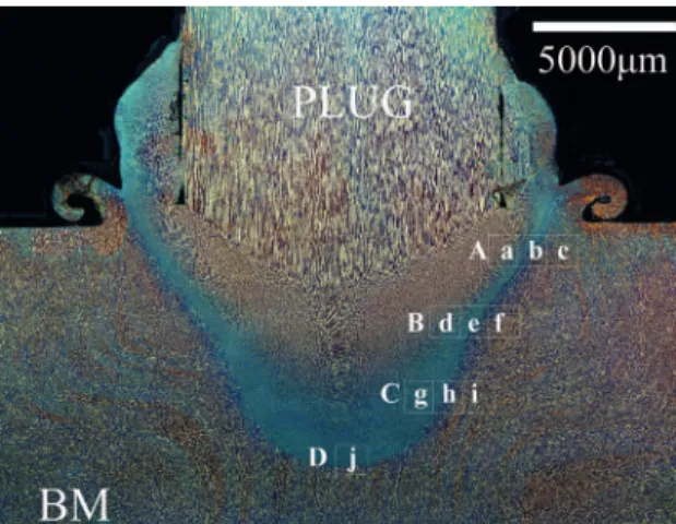
The micrograph in Figure 5-d show that 25 kN welded joint with a complete bonding and therefore will be the only used in the following tests. To the 25 kN welded joint sample, the microstructural analysis showed diferent zones. These zones are normally called the Heat Afect Zone of Plug (HAZ-Plug), Thermo-Mechanically Afected Zone of Plug (TMAZ-Plug), Mixing Zone (MZ), Thermo-Mechanically Afected Zone of Base Material (TMAZ-BM) and heat Afected Zone of Base Material (HAZ-BM) respectively (Figure 7).
Those DSS welded joint common microstructure zones are shown in Figure 8. In same Figure, to the next analysis, the microstructures were divided in regions called region A, region B, region C and region D. In the Mixing Zone, all three forms of austenite phase were observed (Figure 9), i.e. grain boundary allotriomorphs (GBA), Widmanstätten (WA) structure of austenite and transgranular austenite particles (IGA)23. However WA was predominant and it occurs
when higher heat input are provided24. With coarsening of
WA improving the low temperature toughness, afecting corrosion state25.
The Figure 10–b-e-h show that the precipitation of secondary austenite in form of Widmanstätten needles from ferrite grain boundaries enhanced when deeper in the MZ. Yang et al25 shown that both GBA and WA had
higher chromium contents and PREN (Pitting Resistance Equivalent Number) values than IGA, indicating a better pitting resistance. Gunn26 and Karlsson et al.27 already
had reached these results in their DSS studies. It was observed small amount of particles of transgranular austenite (IGA), because IGA requires more driving force to nucleate inside the grains28. During cooling
Figure 4: Acquisition data in diferent welding conditions. a) Speed 5000 RPM, of 6 mm, Force 5 kN. b) Speed 5000 RPM, Burn-of 6 mm, Force 10 kN. c) Speed 7000 RPM, Burn-Burn-of 9 mm, Force 18 kN. d) Speed 7000 RPM, Burn-Burn-of 9 mm, Force 25 kN.
Figure 6: Micrographs of 18 kN showing insuicient mixing and
lack of bond.
Figure 7: Schematic illustration showing the diferent zones observed.
Figure 8: Microstructure 25 kN zones divided into regions.
Figure 9: Mixing zone (MZ) shows Widmanstätten (WA), grain
boundary allotriomorphs (GBA) and transgranular austenite particles (IGA).
in MZ to satisfy the duplex criteria due to rapid cooling achieved which ensures mechanical properties. MZ gave ferrite levels of 55 to 68% that are according with the recommendations from the standard DNV-RP-F112. (Table
3), being important to mention that in diferent heights of MZ-Regions a gradual α-decrease was observed: A-MZ-68%, B-MZ-65%, C-MZ-61%, D-MZ-56%.
In the MZ, at the tip of the processed plug (Figure 10-l), is possible to see the formation of a microduplex structure. This microstructure results when a second phase
precipitation precedes or occurs during recrystallization29.
This microduplex structure was classiied with a super-plastic behavior (elongation of several 100% before failure)26.
According Gunn26, this phenomenon requires slow strain
rates (a few mm/min), temperature of at least 0.6 Tm (where Tm is the absolute melting temperature) and very ine structure. Some authors4,26 describe ways to obtains
Figure 10: According to Figure 8 in diferent Heights, the a), d) and g) are TMAZ-Plug, the b), e) and h) are MZ, the c), f) and i) are TMAZ-BM. The j) k) and l) shows the detail of bonding tip plug.
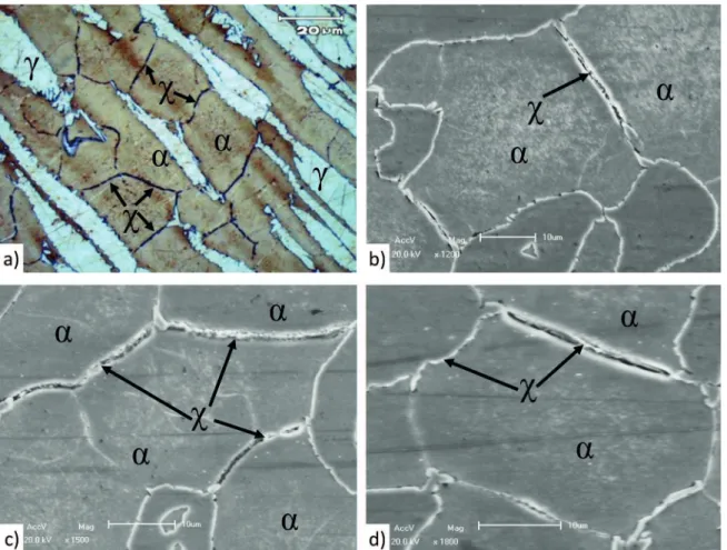
Table 3: Ratio α/γ and γ spacing.
Region Zone α % %RA α γ% %RA γ γ spacing (µm) %RA γ spacing
A
TMAZ-Plug 57,63 9,32 42,37 7,94 10,39 4,47
MZ 67,69 12,51 32,31 4,34 22,78 6,96
TMAZ-BM 61,17 5,75 38,83 5,96 14,76 3,34
B
TMAZ-Plug 67,55 8,71 32,45 4,74 11,12 5,36
MZ 65,17 13,61 34,83 4,97 21,75 7,49
TMAZ-BM 65,61 9,83 34,39 4,83 16,95 4,31
C
TMAZ-Plug 64,70 7,25 35,3 5,12 18,83 5,82
MZ 61,09 11,54 38,91 6,07 19,26 7,38
TMAZ-BM 66,43 9,89 33,57 4,64 17,70 6,49
D
TMAZ-Plug 61,09 8,21 38,91 6,08 23,43 4,83
MZ 55,83 14,03 44,17 8,25 9,03 9,16
TMAZ-BM 59,98 7,18 40,02 7,76 22,43 8,65
Non process material
Plug lengthwise 49,63 4,80 50,37 4,93 31,54 6,73 Plug transverse 55,01 5,28 44,99 4,46 24,43 6,80
3.2. 25 kN phase ratio α/γ, γ spacing and χ-phase
EDS analysis
Normally, all fabrication process that tends to decrease austenite spacing are favorable because decrease the free ferrite path which generally propagates Hydrogen Induced Stress Cracking (HISC). Ofshore Standard DNV-RP-F11230
conirm that materials with ine phase γ spacing have greater resistance to HISC than materials with coarse phase spacing. The austenite spacing is considered ine if it is less than 30 micrometers. In the next Table 3 is possible to see that the results as-welded of γ spacing and phase ratio α/γ are showing containing the %RA (relative accuracy) which proved satisfactory. Furthermore the Table 3 shows that the Austenite spacing in the MZ is approximately in the range of 4 to 24 µm with a gradual decreases when going from region A to D: A-MZ-23,88 µm, B-MZ-21,77 µm, C-MZ-16,74 µm, D-MZ-4,39 µm.
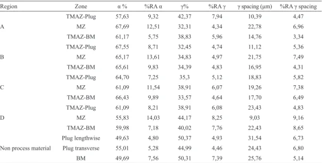
The weld metal and the HAZ in root area of the clad pipe seam welds, any pipe end clad welds and the seal welds of lined pipe shall be essentially free from grain boundary carbides, nitrides and intermetallic phases. Essentially free from intermetallic phases after processing implies that occasional strings of detrimental phases along the centerline of the base material is acceptable given that the phase content within one ield of vision (at 400X magniication) is < 1.0% (max. 0.5% intermetallic phases)31. In the BM and MZ region, the
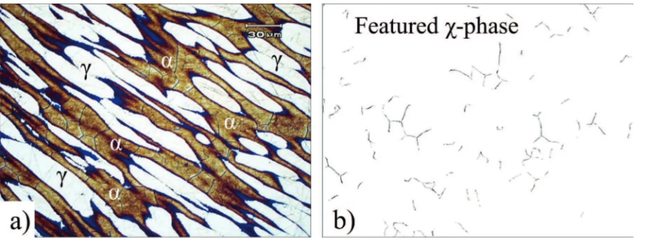
intermetallic phases were not found. The analysis was taken in worst detected Region which was between the HAZ-plug and TMAZ-plug. The results at 400X magniication were < 0.42% intermetallic phases. In Figure 11 the microstructure of referred result. In that case, the intermetallic phase is the χ-phase according other researchers7,32,33.
The intermetallic χ-phase (Figure 12) can be identiied on the basis of BSE (back scattered electrons) contrast in SEM because chi phase is rich in the element molybdenum7,34.
Andrews32 and another researchers33, showed that χ-phase
appears only in the Fe–Cr–Mo ternary and in the Fe–Cr– Ni–Mo and Fe–Cr–Ni–Ti quaternary systems. The Energy-dispersive X-ray spectroscopy (EDS) showed that the large amount molybdenum in intermetallic phase Table 4.
Figure 11: Microstructure of referred result used for measure % intermetallic phases according DNV-RP-F11230.
3.3. 25 kN hardness analysis
During the processing, FHPP is produced by friction and pressure. In the inal process has only the action of forging pressure which the consumable plug is pressed against base material causing a severe plastic deformation. It was proposed that three main strengthening mechanisms of weld zones for friction welding: strain hardening, decreasing grain size and microstructural transformation, and probably, are those strengthening mechanisms of FHPP welds. The hardness distribution proiles of 25 kN sample (Figure 13) which is evaluated according to the three lines testing. The results indicates that hardness values ranging from 250 HV0.5 to 290 HV0.5 are commonly found between MZ and TMAZ-Plug regions. Both in the zone HAZ-Plug as in zone HAZ-BM exhibit lower value in the range of 245–280 HV0.5, practically the same as BM. Besides, results along the four testing lines within MZ reveal that the hardness distribution is heterogeneous because has some singular points with higher hardness values. The increase of hardness between MZ and TMAZ-Plug indicates that materials in both regions are strengthened after welding. In previous works for FHPP6,35 shows that hardness distribution diference
around the zones is common. As shown in Figure 9 and Figure 10, the microstructure of MZ is mainly secondary austenite in the form of Widmanstätten needles from the ferrite grain boundaries.
4 Conclusions
For the irst time this DSS material was investigated in FHPP welds with forces variation from 5 to 25 kN. The results showed the eiciency in DSS structure repair using FHPP with the 25 kN force. It was possible the production of DSS joints according with the recommendations from the standard DNV-RP-F112. The following conclusions could be drawn:
Figure 12: Scanning electron microscopy micrographs of α, γ and χ phases of the duplex stainless steel Processed by FHPP. Etching: Behara modiied.
Table 4: Contents of principal metallic elements in γ, α and χ-phases as determined by EDS after FHPP in DSS (wt.%).
Si Cr Mn Mo Ni Fe
γ 0.691 21.22 2.93 2.51 6.14 66.51
α 0.919 23.72 2.64 3.21 4.21 65.55
χ 0.716 23.74 1.44 11.84 2.26 55.26
Figure 13: Hardness distribution in 25 kN sample.
standard requirements as welded joint because was the only with a complete mixing and bonding without defects.
In Mixing zone (MZ) at the tip of the processed plug was possible to see a microduplex structure formed. It was
the irst time in which the microduplex structure was cited with the FHPP process and the DSS material.
In this investigation, microstructure of FHPP process in DSS reveals three distinct forms of austenite phases i.e. grain boundary allotriomorphs (GBA), Widmanstätten structure (WA) and transgranular austenite particles (IGA). The microstructure of the weldment shows excessive formation of secondary austenite phases in the form of Widmanstätten structure in the Mix zone (MZ) of the weld. The precipitation of Widmanstätten needles from the ferrite grain boundaries increases the strenght in this region.
The results as-welded γ spacing and α levels was approved according the Ofshore Standard DNV-RP-F112 requirements.
Occurred a low variation of the microhardness. The increase of hardness between MZ and TMAZ-Plug indicates that materials in both regions are strengthened after FHPP process.
5. Acknowledgments
The authors acknowledge the inancial support of LAMEF and especially Diogo Busati, Francisco Bandeira, Facundo Lopez and Rafael Eugênio for supporting the experiment and positive suggestions.
6. References
1. Antony PJ, Singh Raman RK, Mohanram R, Kumar P, Raman R.
Inluence of thermal aging on sulfate-reducing bacteria (SRB)-inluenced corrosion behaviour of 2205 duplex stainless steel.
Corrosion Science. 2008;50(7):1858-1864.
2. Alvarez-Armas I, Degallaix-Moreuil S. Duplex Stainless Steels. New Jersey: Wiley-ISTE; 2009. 464p.
3. Lippold JC, Kotecki DJ. Welding Metallurgy and Weldability of Stainless Steels. New Jersey: Wiley-Interscience; 2005. 376p.
4. Lo KH, Shek CH, Lai JKL. Recent developments in stainless steels.
Materials Science and Engineering: R: Reports. 2009;65(4-6):39-104.
5. Michalska J, Sozańska M. Qualitative and quantitative analysis of σ and χ phases in 2205 duplex stainless steel. Materials Characterization. 2006;56(4-5):355-362.
6. Ambroziak A, Gul B. Investigations of underwater FHPP for welding steel overlap joints. Archives of Civil and Mechanical Engineering. 2007;7(2):67-76.
7. Escriba DM, Materna-Morris E, Plaut RL, Padilha AF. Chi-phase precipitation in a duplex stainless steel. Materials Characterization. 2009;60(11):1214-1219.
8. Meyer A. Friction Hydro Pillar Processing - Bonding Mechanism and Properties. Geesthacht: GKSS; 2003. 123p.
9. Yeh FWT, Pereira da Cunha PHC, Lessa CRdeL, Clarke T, Strohaecker, T. Evaluation of Discontinuities in A36 Steel Repairs with Friction
Hydro Pillar Processing Using Diferent Axial Forces. ISIJ International. 2013;53(12):2269-2271.
10. Hattingh DG, Bulbring DLH, Els-Botes A, James MN. Process
parameter inluence on performance of friction taper stud welds
in AISI 4140 steel. Materials & Design. 2011;32(6):3421-3430. 11. Nicholas ED. Friction Processing Technologies. Welding in the
World. 2003;47(11):2-9.
12. Thomas WM, Nicholas ED, Dolby RE, Jones CJ, Lilly RH, inventors.
Friction plug extrusion. International patent, PCT/GB92/01540.
1992 Aug 21.
13. Yin Y, Yang X, Cui L, Cao J, Xu W. Investigation on welding parameters and bonding characteristics of underwater wet friction taper plug welding for pipeline steel. The International Journal of Advanced Manufacturing Technology. 2015;81(5):851-861. http://
dx.doi.org/10.1007/s00170-015-7281-1.
14. Baosheng Z, Xiangdong J, Jiaqing C, ZongYi Q. Numerical simulation
onto the preliminary period of Friction Hydro Pillar Processing in Friction Stitch Welding. In: Proceedings of 2010 International Conference on Mechanic Automation and Control Engineering; 2010 Jun 26-28; Wuhan, China. p.5617.
15. Lessa CRde L, Caregnato MF, Cunha PHCP, Chludzinski M, Strohaecker TM, Macedo MLK, et al. Microstructural evaluation of a C-Mn steel welded by the friction hidro-pillar process. Soldagem & Inspeção. 2011;16(1):2-11.
16. Lessa CRdeL. Soldagem FHPP - processo e metalurgia nas transformações das fases de um aço C-Mn. [Dissertation]. Porto Alegre: Universidade Federal do Rio Grande do Sul; 2011. 17 Pinheiro GA. Local Reinforcement of Magnesium Components by
Friction Processing: Determination of Bonding Mechanisms and Assessment of Joint Properties. Geesthacht: GKSS-Forschungszentrum
Geesthacht GmbH/Universität Hamburg; 2008.
18. Cui L, Yang X, Wang D, Hou X, Cao J, Xu W. Friction taper plug welding for S355 steel in underwater wet conditions: Welding performance, microstructures and mechanical properties. Materials Science and Engineering: A. 2014;611:15-28.
19. Gibson BT, Lammlein DH, Prater TJ, Longhurst WR, Cox CD, Ballun MC, et al. Friction stir welding: Process, automation, and control.
Journal of Manufacturing Process. 2014;16(1):56-73. http://dx.doi.
org/10.1016/j.jmapro.2013.04.002
20. Blakemore G. Friction Welding - Technology for the New Millennium. In: Ofshore Technology Conference; 1999 May 3-6; Houston, Texas,
USA. http://dx.doi.org/10.4043/11063-MS
21. Chludzinski M. Avaliação da tenacidade à fratura em juntas soldadas por fricção com pino consumível [PhD Thesis]. Porto Alegre: Universidade Federal do Rio Grande do Sul; 2013.
22. Hattingh DG, van Zyl C. Temperature Distribution for a Friction Taper
Stud Weld in Thick Walled 10CrMo910 Steel. R & D Journal of the South African Institution of Mechanical Engineering. 2012;28:37-45. 23. Badji R, Bouabdallah M, Bacroix B, Kahloun C, Belkessa B, Maza
H. Phase transformation and mechanical behavior in annealed 2205 duplex stainless steel welds. Materials Characterization. 2008;59(4):447-453.
24. Ureña A, Otero E, Utrilla MV, Múnez CJ. Weldability of a 2205 duplex stainless steel using plasma arc welding. Journal of Materials Processing Technology. 2007;182(1-3):624-631.
25. Yang Y, Yan B, Li J, Wang J. The efect of large heat input on
the microstructure and corrosion behaviour of simulated heat
afected zone in 2205 duplex stainless steel. Corrosion Science. 2011;53(11):3756-3763.
26. Gunn R, ed. Duplex stainless steels: microstructure, properties and applications. Cambridge: Abington Publishing; 2003.
27. Karlsson L, Ryen L, Pak S. Precipitation of intermetallic phases in 22% Cr duplex stainless weld metals. Weldelding Research Supplement. 1995;74:28s-40s.
28. Vinoth Jebaraj A, Ajaykumar L. Inluence of Microstructural Changes
on Impact Toughness of Weldment and Base Metal of Duplex Stainless Steel AISI 2205 for Low Temperature Applications.
Procedia Engineering. 2013;64:456-466.
29. Davis JR, ed. Stainless Steels. Materials Park: ASM International; 1994. 30. Det Norske Veritas. Design of duplex stainless steel subsea equipment exposed to cathodic protection. Høvik: Det Norske Veritas; 2008. 31. Det Norske Veritas. Submarine Pipeline Systems. Høvik: Det Norske
Veritas; 2013.
32. Andrews KW. A New Intermetallic Phase in Alloy Steels. Nature. 1949;164:1015.
33. Kasper JS. The ordering of atoms in the chi-phase of the iron-chromium-molybdenum system. Acta Metallurgica. 1954;2(3):456-461.
34. Chen TH, Weng KL, Yang J. The efect of high-temperature exposure
on the microstructural stability and toughness property in a 2205 duplex stainless steel. Materials Science and Engineering: A. 2002;338(1-2):259-270.