This paper presents a comparative analysis of the results obtained in static modulus of elasticity tests of plain concrete cylindrical specimens. The purpose of this study is to identify and evaluate the inluence of several factors involved in modulus of elasticity tests such as the strain measurement device used (dial indicators, electrical surface bonded strain gages, externally ixed strain gages and linear variation displacement transducer - LVDT), the type of concrete (Class C30 and Class C60) and cylindrical specimen size (100 mm x 200 mm and 150 mm x 300 mm). The modulus tests were done in two different laboratories in the Goiânia, GO region and were performed according to code ABNT NBR 8522:2008, which describes the initial tangent modulus test, characterized by strains measured at tension values of 0.5 MPa and 30% of the ultimate load. One hundred and sixty specimens were tested with statistically satisfactory results. It was concluded that the type of strain measurement device greatly inluenced the modulus of elasticity results. Tests in specimens 100 mm x 200 mm showed highest statistical variation.
Keywords: concrete; specimen size; measurement; modulus of elasticity.
Este trabalho apresenta uma análise comparativa dos resultados obtidos em ensaios do módulo estático de elasticidade realizados em corpos de prova cilíndricos de concreto simples. O objetivo é identiicar e avaliar a inluência de alguns fatores intervenientes nos resultados do ensaio módulo de elasti -cidade como o tipo de equipamento utilizado para medição de deformações (compressômetro mecânico, extensômetro elétrico de colagem supericial, extensômetro elétrico de ixação externa e transdutor diferencial de variação linear, também conhecido pela sigla em inglês – LVDT), diferentes classes do concreto (Classe C30 e Classe C60) e tamanho do corpo de prova (100 mm x 200 mm e 150 mm x 300 mm). Este ensaio foi executado em dois laboratórios da região de Goiânia, GO, conforme a ABNT NBR 8522:2008 que descreve o ensaio de módulo de elasticidade tangente inicial, caracterizando a deforma -bilidade do concreto submetido às tensões entre 0,5 MPa e 30% da tensão de ruptura. Foram realizados ensaios em 160 corpos de prova considerando os resultados com desempenho estatisticamente satisfatório. Concluiu-se que o tipo de medidor de deformação inluenciou signiicativamente os resultados de módulo de elasticidade. Os corpos de prova de dimensão 100 mm x 200 mm apresentaram resultados com as maiores dispersões.
Palavras-chave: concreto; dimensão; medidor; módulo de elasticidade.
Inluence of the type of measuring device in determining
the static modulus of elasticity of concrete
Inluência do tipo de medição na determinação
do módulo estático de elasticidade do concreto
S. S. ArAújo a
G. N. GuImArãeS b
A. L. B. Geyer c
a Masters Degree in Civil Engineering from the Federal University of Goiás, Brazil (2011), School of Civil Engineering, Research Assistanship from CNPq - National Council of Scientiic and Technological Development. E-mail: [email protected]. Address: Universidade Federal de Goiás. Rua Maria Senhorinha de Jesus, Quadra 14-A, Lote 10, Setor Oriente Ville, CEP: 74.355-666 – Goiânia, GO – Brasil.
b PhD., University of Texas at Austin, USA (1988). Full Professor at the Federal University of Goiás, Brazil. E-mail: [email protected] Address: Universidade Federal de Goiás, Escola de Engenharia Civil, Laboratório de Estruturas. Av. Universitária, Pça. Universitária, s/n, Setor Universitário, CEP 74640-220, Goiânia, GO – Brasil.
c Doctorate in Civil Engineering from the Federal University of Rio Grande do Sul, Brazil (2001). Associate Professor II at the Federal University of Goiás. E-mail: [email protected]. Address: Universidade Federal de Goiás, Escola de Engenharia Civil, Laboratório de Materiais de Construção. Av. Universitária, Pça. Universitária, s/n, Setor Universitário, CEP 74640-220, Goiânia, GO – Brasil.
Received: 23 Jan 2012 • Accepted: 02 May 2012 • Available Online: 02 Oct 2012
Abstract
1. Introduction
The use of the modulus of elasticity is frequently related to dis-placement and delection calculations in the design phase of a reinforced concrete structure. The structural engineer speciies a value for the modulus of elasticity of the concrete which he uses in his calculations to satisfy serviceability limit states. This value for the modulus of elasticity will be later veriied during the construc -tion phase by the construc-tion engineer or the concrete contractor. An incorrect veriication of the modulus of elasticity can have seri -ous consequences for the structural design, for example, exces-sive delections not foreseen during the design phase.
Several factors can inluence the value of the concrete’s modulus of elasticity [8,10,14] such as concrete compressive strength, concrete specimen casting process, loading and unloading speed of the test-ing apparatus, mortar content, type of strain measurement device, aggregate type and size, testing machine operator, concrete speci -men size. This research had the objective to study and evaluate the inluence of some of these variables on the static modulus of elastic -ity: inluence of measurement device (dial or digital indicator, surface mounted strain gages, externally ixed strain gages or clip gages, linear variable differential transformer – LVDT), concrete type (Class C30 and Class C60) and cylindrical specimen size (100 mm x 200 mm e 150 mm x 300 mm). Tests were conducted in two different concrete laboratories in the Goiânia, GO region.
The modulus of elasticity can be deined as a relation between the applied stress and the measured strain below yield stress. Accord -ing to code ABNT NBR8522:2008 [3], the static modulus of elastic -ity for a concrete loaded in axial compression is determined by the inclination of the stress-strain curve obtained in testing cylindrical concrete specimens. The specimen is subjected to incrementally increasing loads and the strain is measured at each load incre-ment. The types of modulus of elasticity are related to different loading stages and should be chosen based on the purpose of the test. Figure 1 shows the different types of static modulus of elastic -ity in concrete subjected to compression.
Briely, the moduli of elasticity are:
n Initial tangent modulus: is given by the inclination of a tangent line at the origin of the stress-strain diagram. It is used to char -acterize concrete delections at very low stresses.
n Tangent modulus at a given stress: is the inclination of a tan -gent line of the stress-strain diagram at any given stress. It is used to simulate the structure to loading or unloading at differ-ent loading stages. Loading and unloading can be applicable, for example, when a numerical structural analysis is needed due to large accidental loads.
n Secant modulus: is given by the inclination of a secant line obtained between any two points in the stress-strain dia-gram. Frequently the points chosen correspond to a stress of 0.5MPa and a stress at 50% of the ultimate stress. In this case, it simulates the structure during its initial loading stage when permanent loads prevail. The Brazilian Code for Design and Execution of Reinforced Concrete Constructions ABNT NBR 6118:2003 [4] proposes a value for the secant modulus as 85% of the initial tangent modulus. The secant modulus is frequently used by structural engineers in design.
In this work, the initial tangent modulus of elasticity was deter -mined. It was done according to code ABNT NBR 8522:2008 [3] which prescribes, in this case, concrete strains at stress levels of 0.5 MPa and 30% of ultimate stress. This code prescribes an initial stress of 0.5 MPa, and not a zero value, to minimize the effect of specimen imperfections, testing machine variability and the ac-commodation process of the top and bottom plates of the testing machine, since these factors can generate in initial disturbance in the stress-strain diagram near zero stress.
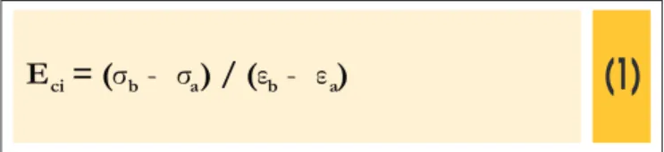
The value of the initial tangent modulus of elasticity, Eci, is given by the equation below:
(1)
E
ci= (
σ
b- σ
a) / (
ε
b- ε
a)
where:
σb is the higher stress and it is equal to 0.3 of the rupture stress;
σa is the basic stress and is equal to 0.5 MPa;
εb is the average strain of the specimen under the higher stress;
εa is the average strain of the specimen under the basic stress;
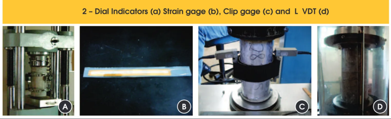
Contrary to strain measurements in steel rebars, strain measure -ments in concrete are much harder to obtain. In steel, strain measur -ing devices known as strain gages are widely used and give good quality and reliable results. But in concrete, the same does not hap -pen and several researchers [6,7,8,9] and laboratories in Brazil and worldwide have search for other alternatives to obtain reliable strain measures with less statistical variability. Among these alternatives for measuring strains in concrete, the present research work veriied the use of four different measuring devices [15,16]: dial indicator, surface bonded strain gages, externally ixed strain gages or clip gages, linear variable differential transformer – LVDT.
The digital or dial indicator is a mechanical measuring device where a small piston moves indicating the measurement. Both the strain gage and the clip gage work based on the same principle of changes in the electrical resistance of a coil during the deformation of the body to which they are attached. The difference is that the strain gage is bonded (glued) to the body surface and the clip gage
Figur
1 – Dif ferent types of modulus
e
Tests with the dial gages and strain gages were done at Carlos Campos Laboratories and tests with clip gages and LVDTs were done at Furnas Centrais Elétricas Laboratories. It was not possible to conduct all tests at the same laboratory due to physical and op-erational constraints (equipment, operating hours, operator avail-ability, storage) of the two laboratories involved and the quantity of specimens to be tested.
The loading stages known as Metodology A in code ABNT NBR 8522:2008 [3] was used for the modulus of elasticity tests. Cycles of loading and unloading were done. According to Figure 3, strain measurements were taken at stress levels of 0.50 MPa and 30% of the rupture stress (known as fc) and the initial tangent modulus
was calculated according to Equation 1.
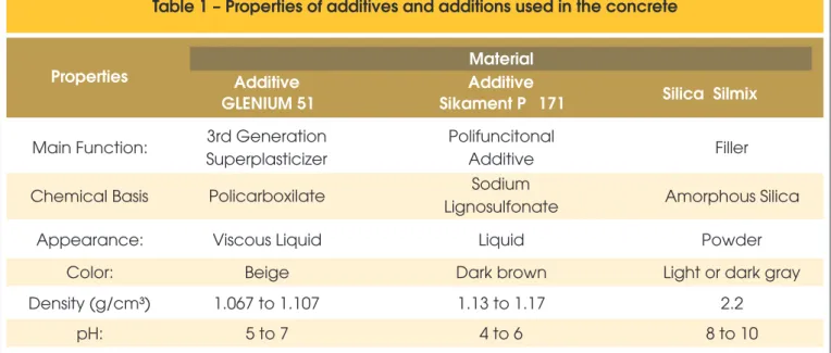
Conventional concrete Class C30 and Class C60 were used. These were cast in concrete mixers with a maximum capacity of 450 liters using Portland cement Type V ARI (high initial strength) fabricated by CIMPOR. Silica fume, superplasticizers and polyfunctional ad -ditives were also used in the concrete mix. The properties of the additives and admixtures used are presented in Table 1. The mix proportions are presented in Tables 2 and 3. All specimens were cast at Carlos Campos Laboratories.
Ten cylindrical specimens were cast for compressive strength tests for each type of concrete (class C30 and C60), for each specimen dimension (100 mm x 200 mm e 150 mm x 300 mm) and for each laboratory, for a total of 80 specimens. These tests were done in the two laboratories (40 specimens tested in each laboratory) at 28 days after casting. The compressive strength test is needed prior to the modulus tests so the value of 30% of rupture stress can be calculated for use in the modulus tests and in Equation 1. The rup-ture stress was calculated as the average of the ruprup-ture stresses of the 10 specimens.
Ten cylindrical specimens were cast for the modulus of elastic-ity tests for each measurement device (4 different devices), for each type of concrete (class C30 and C60), and for each speci -men di-mension (100 mm x 200 mm e 150 mm x 300 mm), for a total of 160 (10x4x2x2) specimens. Tests using the dial indicators and strain gages were done simultaneously on the same concrete specimen, so not all specimens cast were used. This was possible, since, during the test, the analogical readings from the dial indica-tors were obtained visually by the operator, and the strain gage readings were digital and obtained using a microcomputer. All tests were done 28 days after casting. The modulus test is non -destructive and the same specimen was then taken to rupture to is mechanically ixed to the surface through claws, permitting their
reuse. The strain gage is disposable after the test. The linear vari-able differential transformer is better known by its acronym LVDT and it is an electro-magnetic displacement transducer. Figure 2 shows photos of these 4 measuring devices.
As far as loading speed, code ABNT NBR 8522:2008 [3] speciies a loading speed for the modulus of elasticity test at (0.45±0.15) MPa/s. The laboratory where the test is undertaken chooses the loading speed. In the research, the loading speed used was 0.6 MPa/s at both labs.
2. experimental program
Considering the characteristics of the interlaboratory program, three variables were considered:
n Type of conventional concrete (class C30 and class C60); n Type of strain measurement device (dial gages, strain gages,
clip gages and linear variation displacement transducer - LVDT); n Cylindrical specimen dimensions: 100 mm x 200 mm and 150
mm x 300 mm.
F igur
2 – Dial Indicators (a) Strain gage (b), Clip gage (c) and L VDT (d)
e
A
B
C
D
Figur
3 – Loading history for determining
e
ABNT NBR 5738:2008 [1], following guidelines in code ABNT NBR 5739:2007 [2]. To reduce the inluence of specimen humidity, after 24 hours after casting, the specimens were identiied and stored in water tanks for 28 days. After this, the specimens were removed from the storage tanks and stored at room temperature and humid -ity. Sulfur capping was used in all specimens.
The specimens were grouped in packages of 10 specimens and obtain its compressive strength. The objective of testing the same
specimen for compressive strength after the modulus test is to verify the homogeneity of the concrete and to allow statistical con-trol. However, these compressive strength results were not used in Equation 1. The values used were obtained in the compressive strength tests mentioned earlier.
Specimens were cast and stored according to provisions in code
Table 1 – Properties of additives and additions used in the concrete
Properties
Additive
Material
GLENIUM 51
Additive
Sikament P
F
171
Silica
Fume
Silmix
Main Function:
3rd Generation
Superplasticizer
Polifuncitonal
Additive
Filler
Chemical Basis
Policarboxilate
Sodium
Lignosulfonate
Amorphous Silica
Appearance:
Viscous Liquid
Liquid
Powder
Color:
Beige
Dark brown
Light or dark gray
Density (g/cm³)
1.067 to 1.107
1.13 to 1.17
2.2
pH:
5 to 7
4 to 6
8 to 10
!"#$%&' '
()* ! +,-./01-2/3.4
W
/
C
*
5 6 #7" )5 '
Q
Cement CP V ARI
236 kg
Artificial sand
891 kg
Gravel size 1 (19 mm)
999 kg
Water
172 kg
Polyfuncitonal Additive
1.65 kg (0.7% of cement)
Superplasticizer
0.94 kg (0.4% of cement)
Silica Fume
18.9 kg (as replacement for 8% of
cement in weight)
Fresh
Concrete
Properties:
Consistency
130 mm
were randomized before the modulus of elasticity tests. Random -ization was done to allow minim-ization of certain variables effects that could not or were not considered in the experiment such as: casting process, aggregate distribution in the concrete, testing de-vice setup, among others. Also, if any dependency mechanism ex -ists between subsequent experimental results, the randomizations of the tests allow this dependency to be diluted among all studied situations, thus not favoring a certain situation over another. Statistical analysis of variance technique (ANOVA) was applied using software Statsoft Statistica 7®, for concrete Class C30 and
for concrete Class C60 specimens, separately and together. The test methodology consists in the application of Fisher’s Test. This analysis indicated that the results should be analyzed together to be statistically signiicant.
3. Presentations and discussion
of results
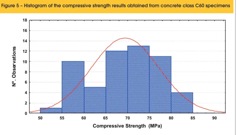
In order to verify the homogeneity of the concrete used, the com -pressive strength results of the specimens taken to rupture right after the modulus of elasticity tests were irst analyzed. These compressive strength results were analyzed by statistical methods in order to identify possible variances of the results and to verify the normal distribution (histogram) of the results. Figures 4 and 5 show the histograms of these compressive strength results for con-crete classes C30 and C60, respectively. Concon-crete C30 showed an average compressive strength of 36.5MPa with a coeficient of variation of 10% and concrete C60 showed an average compres -sive strength of 69.3 MPa with a coeficient of variation of 11%.
The comparison between the histograms and the normal distribu-tion curve was analyzed by the Kolmogorov-Smirnov e Qui-square methods. From a statistical point of view, a value of 10% is an ac -ceptable level for variability for a measuring process.
Table 4 presents the averages, standard deviations and coef -icients of variation of the results obtained in all of the situa -tions studied with a 95% conidence interval from the average for the modulus of elasticity property. A statistical analysis of variance (ANOVA) was done with the modulus of elasticity re -sults to determine the statistically signiicant factors with a 95% conidence level. Some values were removed, since they did not it the conidence interval and they were eliminated by the Chauvenet criteria.
Table 4 shows that the measuring devices that presented the smallest dispersions were the strain gages and the clip gages since the total coeficients of variation of these devices were 11.0% and 14.4%, respectively, and the total coeficients of variation of the dial indicators and the LVDTs were 16.1% and 18.2%, respectively.
Table 4 also shows that the specimens with 100 mm x 200 mm dimensions presented higher dispersion of results, because their total coeficient of variation was 24.4% and the total coeficient of variation of the specimens with 150 mm x 300 mm dimensions was 13.1%.
Since ANOVA revealed that the specimen size, type of measuring device and type of concrete were statistically signiicant, grouping homogeneous averages by the Duncan method was done to ob-serve the differences and similarities of the results obtained. This method demonstrated that the two specimen sizes inluenced the values of the modulus of elasticity of the concrete because the
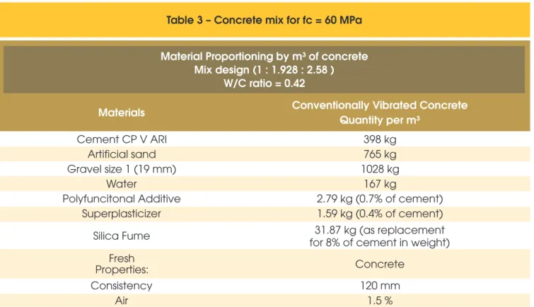
Table 3 – Concrete mix for fc = 60 MPa
Material Proportioning by m³ of concrete
Mix design (1 : 1.928 : 2.58 )
W/C ratio = 0.42
Materials
Conventionally Vibrated Concrete
Quantity per m³
Cement CP V ARI
398 kg
Artificial sand
765 kg
Gravel size 1 (19 mm)
1028 kg
Water
167 kg
Polyfuncitonal Additive
2.79 kg (0.7% of cement)
Superplasticizer
1.59 kg (0.4% of cement)
Silica Fume
for 8% of cement in weight)
31.87 kg (as replacement
Fresh
Concrete
Properties:
Consistency
120 mm
average of the modulus for specimens 100 mm x 200 mm and 150 mm x 300 mm were 24.4 GPa e 26.2 GPa, respectively. That is, the specimens 150mm x 300mm had an average 7% higher than
the average obtained for specimens 100mm x 200 mm.
The Duncan method also demonstrated that the strain gages pre-sented results similar to the dial indicators, since their averages for
Figure 4 – Histogram of the compressive strength results obtained from concrete class C30 specimens
18 20 22 24 26 28 30 32 34 36 38 40 42 44 46 48
Compressive Strength (MPa)
0 2 4 6 8 10 12 14 16 18
N
º.
O
bs
er
va
tio
ns
Figure 5 – Histogram of the compressive strength results obtained from concrete class C60 specimens
50 55 60 65 70 75 80 85 90
Compressive Strength (MPa)
0 2 4 6 8 10 12 14 16 18
N
º.
O
bs
er
va
tio
the modulus tests were 27.6 GPa e 27.5 GPa, respectively, and the averages for the clip gages and the LVDTs were 26.3 GPa e 19.8 GPa respectively.
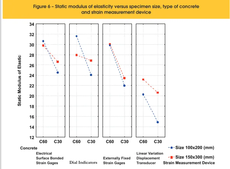
For 100mm x 200 mm specimens, modulus results (see Figure 6) obtained using strain gages had averages of 24.6 GPa and 30.6 GPa and their respective coeficients of variation were 13.2% and 1.9% for concrete classes C30 and C60. Results obtained with dial indicators had averages of 24.1 GPa and 31.6 GPa and their respective coeficients of variation were 16.1% and 17.7% for con -crete classes C30 and C60. Results obtained with clip gages had averages of 22.0 GPa and 29.8 GPa and their respective coef -icients of variation were 4.0% and 2.5% for concrete classes C30 and C60. Results obtained with LVDTs had averages of 14.9 GPa and 20.3 GPa and their respective coeficients of variation were
13.5% and 7.9% for concrete classes C30 and C60. For 100mm x 200 mm specimens, modulus results obtained from dial indicators and LVDTs presented larger variability.
For 150mm x 300 mm specimens, modulus results (see Figure 6) obtained using strain gages had averages of 26.6 GPa and 29.8 GPa and their respective coeficients of variation were 2.6% and 4.0% for concrete classes C30 and C60. Results obtained with dial indicators had averages of 26.9 GPa and 27.9 GPa and their re -spective coeficients of variation were 3.8% and 7.6% for concrete classes C30 and C60. Results obtained with clip gages had aver -ages of 23.5 GPa and 30.8 GPa and their respective coeficients of variation were 4.1% and 1.5% for concrete classes C30 and C60. Results obtained with LVDTs had averages of 20.6 GPa and 23.2 GPa and their respective coeficients of variation were 1.4%
8
able 4 – Statistical analysis of test results – static modulus of elasticity
–
Dial Indicators
–
37
27.5
4.4
16.1
–
Electrical Surface Bonded Strain Gages
–
35
27.6
3.05
11.0
–
Externally Fixed Strain Gages
–
39
26.3
3.8
14.4
–
Linear Variation Displacement Transducer - LVDT
–
37
19.8
3.6
18.2
100X200
–
–
73
24.4
5.96
24.4
150X300
–
–
75
26.2
3.4
13.1
Dial Indicators
C30
10
24.1
3.9
16.1
Dial Indicators
C60
9
31.6
5.6
17.7
Electrical Surface Bonded Strain Gages
C30
10
24.6
3.2
13.2
Electrical Surface Bonded Strain Gages
C60
6
30.6
0.58
1.9
Externally Fixed Strain Gages
C30
10
22.0
0.88
4.0
Externally Fixed Strain Gages
C60
9
29.8
0.74
2.5
Linear Variation Displacement Transducer - LVDT
C30
9
14.9
2.004
13.5
Linear Variation Displacement Transducer - LVDT
C60
10
20.3
1.6
7.9
Dial Indicators
C30
9
26.9
1.02
3.8
Dial Indicators
C60
9
27.9
2.1
7.6
Electrical Surface Bonded Strain Gages
C30
9
26.6
0.69
2.6
Electrical Surface Bonded Strain Gages
C60
10
29.8
1.2
4.0
Externally Fixed Strain Gages
C30
10
23.5
0.96
4.1
Externally Fixed Strain Gages
C60
10
30.1
0.46
1.5
Linear Variation Displacement Transducer - LVDT
C30
8
20.6
0.29
1.4
Linear Variation Displacement Transducer - LVDT
C60
10
23.2
2.9
12.6
(%)
Static Modulus of Elasticity (GPa)
OBS.: - Concrete types: concrete class C30 for dimensions100 mm x 200 mm and 150 mm x 300 mm and concrete class C60 for dimensions 100mm x 200mm and 150mm x 300mm.
– Twelve of the individual results were considered as spurious values.
Situation of Study
N° of
Specimen
Size
(mm)
Type of strain measurement device
Concrete
Type of
Average
(GPa)
Standard
Deviation
Coefficient
of Variation
(GPa)
100X200
and 12.6% for concrete classes C30 and C60. For 150mm x 500 mm specimens, modulus results obtained from dial indicators and LVDTs presented larger variability. Results obtained using LVDTs presented lowest modulus.
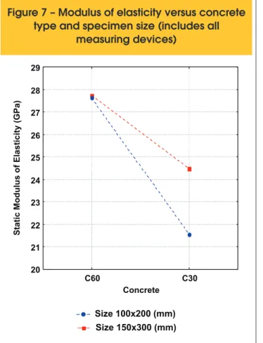
Since 100 mm x 200 mm specimens showed larger variability in the modulus results, the variable “specimen size” was investigated in further with more results shown in Figures 7 and 8. Figure 7 shows the effect of specimen size and the effect of concrete type with con -crete class C60 showing higher modulus results. Modulus results obtained with 100 mm x 200 mm specimens had averages of 21.6 GPa and 27.6 GPa and their respective coeficients of variation were 21.6% and 20.5% for concrete classes C30 and C60. Modulus re -sults obtained with 150 mm x 300 mm specimens had averages of 24.5 GPa and 27.7 GPa and their respective coeficients of variation were 10.8% and 12.2% for concrete classes C30 and C60.
Figure 8 show the effect of measuring device interacting with specimen size and the behavior explained earlier is the same. Again, highest variability is shown in results obtained with LVDTs. For 100mm x 200 mm specimens, modulus results (see Figure 8) obtained using strain gages had an average of 26.8 GPa and the coeficient of variation was 14.7%. Results obtained with dial indicators had an average of 27.7 GPa and the coeficient of varia
-tion was 21.9%. Results obtained with clip gages had an average of 25.7 GPa and the coeficient of variation was 15.9%. Results obtained with LVDTs had an average of 17.7 GPa and the coef -icient of variation were 18.5%. For 100mm x 200 mm specimens, modulus results obtained from dial indicators and LVDTs present-ed larger variability.
For 150mm x 300 mm specimens, modulus results (see Figure 8) obtained using strain gages had an average of 28.3 GPa and the coeficient of variation was 6.6%. Results obtained with dial indicators had an average of 27.4 GPa and the coeficient of varia -tion was 6.2%. Results obtained with clip gages had an average of 26.8 GPa and the coeficient of variation was 12.9%. Results obtained with LVDTs had an average of 22.0 GPa and the coef -icient of variation were 11.3%. For 150 mm x 300 mm specimens, modulus results obtained from clip gages and LVDTs presented larger variability.
4. Conclusion
The analysis of the results obtained before considered the inlu -ence of measuring device, concrete class and specimen size. The most important conclusions of this study were:
9:;<=>?@ABCB:DEFG<H<IFJ>HCIB:D:BKL>=I<IIM>D:E>NI:O>PBKM>FJDFND=>B>
and strain measurement device
Size 100x200 (mm)
Size 150x300 (mm)
Electrical Surface Bonded Strain Gages
C60
C30
12
14
16
18
20
22
24
26
28
30
32
34
Dial Indicators
C60
C30
Externally Fixed Strain Gages
C60
C30
Linear Variation Displacement Transducer
C60
C30
Concrete
vices), and harder to use due to its analog readings, need of constant maintenance, equipment fragility, calibration dificul -ties and manual control by the testing operator.
7. In general, the strain gages and clip gages had more consis -tent readings and lowest coeficients of variation and showed important advantages such as a smaller need of external in-tervention during testing and minimization of reading errors by the operator. In case of strain gages, the bonding of the gage to the concrete surface has various aspects that should be closely watched, making its use more dificult. Also, the strain gages have to be discharged after their use, and a second use is not allowed, which increases testing costs. The clip gages have the advantage of measuring both longitudinal and trans-verse strains, show digital readings and are less susceptible to calibration procedures. Clip gages are more practical, can be reused several times and setting them up on the specimen is easy and no great operator expertise is required.
Modulus of elasticity tests using different measuring devices showed that even when following the criteria speciied in code ABNT NBR 8522:2008 [3], variations in test results are relatively signiicant.
5. Acknowledgements
The authors wish to express special thanks to Laboratory Carlos Campos Consultoria e Construções Ltda., to Laboratório de Fur
-Figure 7 – Modulus of elasticity versus concrete
type and specimen size (includes all
measuring devices)
C60 C30
Concrete
Static Modulus of Elasticity (GPa)
20 21 22 23 24 25 26 27 28 29
Size 100x200 (mm) Size 150x300 (mm)
QRSTUVWXYZ[T\T]Z^V\_]`RaR`b
versus
strain measurement device and
specimen size (SG – strain gage, DI - dial
indicator, CG - clip gage and LVDT)
Static Modulus of Elasticity (GPa)
Size 100x200 (mm) Size 150x300 (mm)
SG DI CG LVDT
Strain Measurement Device 16
18 20 22 24 26 28 30
1. The two specimen sizes used in this study had an effect on the concrete static modulus of elasticity since the average modu-lus obtained from 100 mm x 200 mm and 150 mm x 300 mm specimens were 24.4 GPa and 26.2 GPa, respectively. The average modulus obtained from 150 mm x 300 mm specimens were 7% higher. However, code ABNT NBR 8522:2008 [3] sets tolerance limits in item 8.2 which allows variation in results of up to 10%.
2. Results using strain gages were similar to results using dial gages since their average modulus were 27.6 GPa and 27.5 GPa, respectively. The results for clip gages and LVDTs showed average modulus of 26.3 GPa and 19.8 GPa, respec -tively.
3. For specimen size 100 mm x 200 mm, results showed largest variability when dial gages and LVDTs were used. For 150mm x 300 mm specimens, modulus results obtained from clip gag -es and LVDTs pr-esented larger variability.
4. For the two concrete types, 100 mm x 200 mm specimen re -sults showed larger variability than 150 mm x 300 mm speci -men results. The 150 mm x 300 mm speci-mens had smaller coeficient of variability in the modulus tests.
5. Modulus values obtained using dial gages and strain gages were higher than results obtained with clip gages and much higher than those obtained with LVDTs.
-nas Centrais Elétricas, to Realmix Concreto S.A., to Conselho Na cional de Desenvolvimento Cientíico e Tecnológico – CNPq and to Procad/CAPES.
6. references
[01] ASSOCIAÇÃO BRASILEIRA DE NORMAS TÉCNICAS – ABNT. NBR 5738: Concreto – Procedimento para moldagem e cura de corpos de prova. Rio de Janeiro: ABNT, 2008.
[02] _______. NBR 5739: Concreto – Ensaio de compressão de corpos de prova cilíndricos. Rio de Janeiro: ABNT, 2007.
[03] _______. NBR 8522: Concreto – Determinação do módulo estático de elasticidade à compressão e Diagrama Tensão-Deformação – Método de Ensaio. Rio de Janeiro: ABNT, 2008.
[04] _______. NBR 6118: Projeto e Execução de Obras de Concreto Armado. Rio de Janeiro: ABNT, 2003. [05] CUPERTINO, M. A.; PEREIRA, A. C; INÁCIO, J.J.;
ANDRADE, M.A.S. Avaliação de Fatores de Ensaio que Interferem nos Resultados de Módulo de Elasticidade do Concreto. In: 49º CONGRESSO BRASILEIRO DO CONCRETO, 2007, Bento Gonçalves - RS. Anais 49º Congresso Brasileiro do Concreto. 2007. CD-ROM.
[06] MARTINS, D. G. Inluência do tamanho do corpo de prova nos resultados de ensaios de módulo de deformação e resistência à compressão e suas correlações para concretos produzidos em Goiânia- GO [manuscrito] / Danilo Gomes Martins. – 2008. Dissertação (Mestrado) – Universidade Federal de Goiás, Escola de Engenharia Civil, 2008.
[07] RODRIGUES, G. S. S. Módulo de deformação estático do concreto pelo método ultra-sônico: estudo da correlação e fatores inluentes. Dissertação de Mestrado. Escola de Engenharia Civil, Universidade Federal de Goiás. 2003. 234 p.
[08] ARAÚJO, SUÉLIO DA SILVA. Inluência do tipo de medição na determinação do módulo estático de elasticidade do concreto - 2011. 212 f.: il., igs, tabs. Orientador: Prof. PhD. Gilson Natal Guimarães; Co-orientador: Prof. Dr. André Luiz Bortolacci Geyer. Dissertação (Mestrado) – Universidade Federal de Goiás, Escola de Engenharia Civil, 2011.
[09] FIGUEIREDO, E. J. P.; SOUZA, F. L. S.; DE FIGUEIREDO, A. D. Medidas de deformação através de strain gages. Trabalho da disciplina de tecnologia avançada no estudo do comportamento do concreto. São Paulo, 1989. 57 p.
[10] METHA, P. K.; MONTEIRO, Paulo J. M.
“Concreto-Microestrutura, Propriedades e Materiais.” 1ª Ed. Português, IBRACON, São Paulo, 2008. [11] MONTIJA, Fernando Celloto. Aspectos da
Variabilidade Experimental do Ensaio de Módulo de Deformação do Concreto. 2007. Dissertação (Mestrado em Engenharia de Construção Civil e Urbana) – Escola Politécnica, Universidade de São Paulo, São Paulo, 2007.
[12] SHEHATA, L. D. Deformações Instantâneas do Concreto. In: IBRACON, Concreto: Ensino, Pesquisa e Realizações. Editor: ISAIA, G. S. IBRACON, São Paulo, 2005. cap. 21, p. 633-654. ISBN 85-98576-03-4. [13] ______. NBR 8953 – Concreto para ins estruturais
– Classiicação por grupos de resistência. Rio de Janeiro, 2009.
[14] BARBOSA, Isa Lorena Silva. Inluência dos
agregados graúdos da região de Goiânia no módulo de deformação tangente inicial do concreto - 2009. 133 f.: il., igs, tabs. Orientador: Prof. Dr. André Bortolacci Geyer. Dissertação (Mestrado) –
Universidade Federal de Goiás, Escola de Engenharia Civil, 2009.
[15] PORTNOI, M. Extensometria: história, usos e aparelhos. Disponível em:
http://locksmith.orcishweb.com/academic-iles/ extensometria.html#_Toc511736064. Acesso em 15
jun. 2009.