S. Seitl et alii, Frattura ed Integrità Strutturale, 39 (2017) 100-109; DOI: 10.3221/IGF-ESIS.39.11
100
Focussed on Modelling in Mechanics
Numerical study and pilot evaluation of
experimental data measured on specimen loaded
by bending and wedge splitting forces
S. Seitl
Academy of Sciences of the Czech Republic, v. v. i., Institute of Physics of Materials, Brno, Czech Republic
Brno University of Technology, Faculty of Civil Engineering, Institute of Structural Mechanics, Brno, Czech Republic [email protected], http://orcid.org/0000-0002-4953-4324
R. Diego Liedo
Academy of Sciences of the Czech Republic, v. v. i., Institute of Physics of Materials, Brno, Czech Republic
University of Oviedo, Department of Construction and Manufacturing Engineering, Campus de Viesques, Gijón, Spain [email protected]
ABSTRACT. The fracture mechanical properties of silicate based materials are determined from various fracture mechanicals tests, e.g. three- or four- point bending test, wedge splitting test, modified compact tension test etc. For evaluation of the parameters, knowledge about the calibration and compliance functions is required. Therefore, in this paper, the compliance and calibration curves for a novel test geometry based on combination of the wedge splitting test and three-point bending test are introduced. These selected variants exhibit significantly various stress state conditions at the crack tip, or, more generally, in the whole specimen ligament. The calibration and compliance curves are compared and used for evaluation of the data from pilot experimental measurement.
KEYWORDS. Numerical simulation; Stress intensity factor; T-stress; Concrete; Finite element method; Wedge splitting test; Three–point bending test.
Citation: Seitl, S., Liedo, R. D., Numerical study and pilot evaluation of experimental data measured on specimen loaded by bending and wedge splitting forces, Frattura ed Integrità Strutturale, 39 (2017) 100-109.
Received: 25.07.2016 Accepted: 22.09.2016 Published: 01.01.2017
Copyright: © 2017 This is an open access article under the terms of the CC-BY 4.0, which permits unrestricted use, distribution, and reproduction in any medium, provided the original author and source are credited.
INTRODUCTION
or evaluation of fracture mechanical properties of materials like concrete, standardized methodology is not published yet. There is only recommendation for measurement of properties by RILEM [18]. In the literature, researchers used various specimen geometries for experimental measurement of fracture properties of concrete,
S. Seitl et alii, Frattura ed Integrità Strutturale, 39 (2017) 100-109; DOI: 10.3221/IGF-ESIS.39.11
101
see e.g. wedge splitting test (WST) [4, 5, 7, 14, 15, 21, 23, 24, 31], three–point bend [10, 17], comparison between data from WST and three–point bend (3PB) tests are introduced in [12], modified compact tension (MCT) test [6] and another configurations can be found in handbooks e.g. [11, 27].
Note that from various geometry, the different values of fracture parameters can be obtained for the same material. Therefore the combined WST/3PBT geometry has been investigated, the variants are proposed in [29] Fig. 1 (Variant I represents the classical WST [7, 24] and is included in the study as a reference case), see in [29]. In all these cases the crack propagates from a notch provided on the top side of the specimen (in the groove for inserting of the WST loading fixtures. Finally, the variant IIIb differs from the variant III by the central notch provided also from the bottom surface.), provides a wide range of various stress distributions in the specimen ligament – from bending to tension – which is expected to result in the desired variety e.g. in the fracture process zone size and shape, fracture energy or fracture toughness, etc.
In the paper, the numerical support (calibration and compliance curves) for evaluation of the experimentally obtain data is shown/introduced. The pilot numerical study of the selected shape of specimens by using Williams expansion was introduced in [22, 25, 28, 30]. The values of stress intensity factor (SIF), T-stress and crack opening displacement (COD, see Fig. 2) at the load line for load Psp = 1000 N = 1 kN are introduced. The changes of properties are compared and discussed. These changes could be obtained modifying the specimen length to width and the span to length ratios (and/or simultaneously the wedge angle). At the end of the contribution, examples of the evaluation of experimental data measured by using the studied combination [29] have been presented.
variant I variant III
variant II variant IIIb
S. Seitl et alii, Frattura ed Integrità Strutturale, 39 (2017) 100-109; DOI: 10.3221/IGF-ESIS.39.11
102
Dimensions of specimens for all four geometry variants are summarized in Tab. 1 (dimensions common to all variants) and in Tab. 2, there are unique dimension of all studied variants (I, II, III and IIIb) with angles.
Width Breadth Height Load position Groove depth
W [mm] B [mm] H [mm] h [mm] dn [mm]
150 150 130 8 20
Effective width Groove width Load position Eccentricity
Weff [mm] f [mm] i [mm] e [mm]
142 40 10 20
Table 1: Nominal variant dimensions and test geometry parameters, taken from [29].
Geometry
variant Wedge angle Length Span
Depth of top notch Depth of bottom notch Initial crack length Relative crack length Specimen
set 2αw [º] L [mm] S [mm] c [mm] c1 [mm] a [mm]
α = a/Weff
[-]
I, α1 30 150 0 13 - 25 0.18
I, α2 30 150 0 30 - 42 0.30
II, α1 15 300 270 15 - 27 0.19
II, α2 15 300 270 31 - 43 0.30
II, α3 15 300 270 54 - 66 0.46
III, α1 15, 30 600 540 13 - 25 0.18
III, α2 15, 30 600 540 35 - 47 0.33
III, α3 15, 30 600 540 54 - 66 0.46
IIIb, α1 15, 30 600 540 8 53 53 0.37
IIIb, α2 15, 30 600 540 9 81 81 0.57
Table 2: Nominal variant dimensions and test geometry parameters, taken from [29].
THEORETICAL BACKGROUND
ccording to the two-parameter fracture mechanics approach which uses T-stress as a constraint parameter [1, 11, 13, 24, 34], the stress field around the crack tip of a two-dimensional crack embedded in an isotropic linear elastic body subjected to normal mode I loading conditions is given by the following expressions [33]:
S. Seitl et alii, Frattura ed Integrità Strutturale, 39 (2017) 100-109; DOI: 10.3221/IGF-ESIS.39.11
103
where r and θ are the polar coordinates and x and y are the Cartesian coordinates, both with their origins at the crack tip.
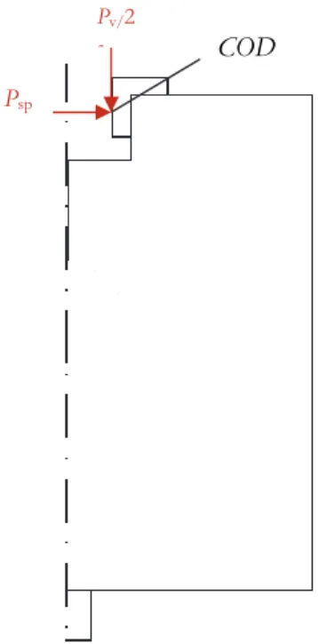
KI is the stress intensity factor for mode I and T is the T-stress. Thus, in two-parameter based fracture mechanics, the stress field is expressed by means of the two parameters, the stress intensity factor KI and the T-stress (see e.g. [1, 11, 24]). The values of crack opening displacement at load line is measured in the axes of roller bearings through which the load of specimens is applied (see e.g. in [4, 14] and sketch of forces in Fig. 2). The applied load ratio between forces is following, [4, 14, 19, 24]:
k P Ps v
2 1
(2)
where
c w
w
w c
ctg k
1 tan
tan
1 , (3)
where αw is the angle of the slope of the wedge and µc refers to friction in the roller bearings.
Figure 2: Detail of boundary conditions, see the half of specimen and the load application (Psp and Pv/2) with crack opening displacement (COD), position at load line.
MODELING IN ANSYS
he finite element software ANSYS [2] is used for numerical calculation of mentioned fracture parameters (K,
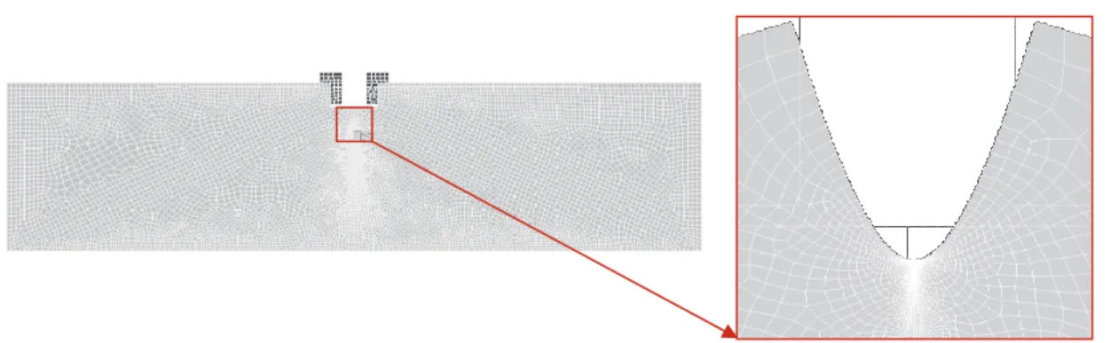
T-stress and COD). Plots of variants of the test geometry selected for the experimental study are shown in Fig. 1. Note that geometries are symmetric for all considered specimen shapes (including boundary conditions); therefore, only one half of the problem was modelled like in [21, 22, 26]. The size of the smallest element in the crack tip is 5 × 10⁻⁵ mm.
The specimen geometry IIIb could leads to crack closure, therefore the whole body of the specimen was modeled and the example of numerical model with applied boundary conditions is shown in Fig. 3. The crack length to depth ratio a/Weff
varies from 0.1 to 0.9. The thickness B is taken as unity in the computations, conditions of plane strain was applied.
T
Psp
COD
Pv/2
S. Seitl et alii, Frattura ed Integrità Strutturale, 39 (2017) 100-109; DOI: 10.3221/IGF-ESIS.39.11
104
Figure 3:Example of numerical model, where boundary conditions are shown, with detail in the vicinity of the crack tip.
The material input data for the concrete used in the numerical simulations were as follows: Ec = 33 000 MPa and νc = 0.2;
and for the steel: Es = 210 000 MPa and νs = 0.3. For good comparison of numerically obtain results for all cases, the load
was applied as splitting force Psp = 1 000 N = 1 kN.
NUMERICAL RESULTS
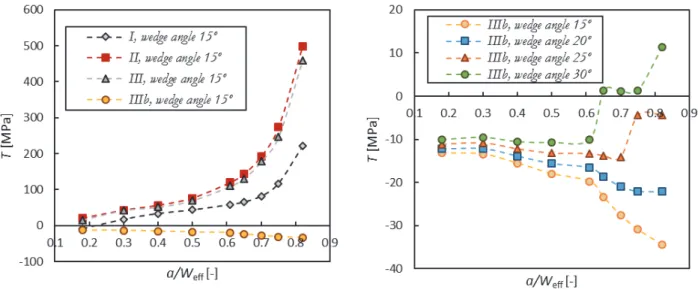
he numerically calculated values of KI and T-stress are given in Figs. 4 and 5, respectively. In the present paper, four cases of the specimens’ shapes/arrangements on the calibration curves were investigated, see Fig. 1 (I, II, III and IIIb) for wedge angle: 15, 20 25, 30.
On the left side of Fig. 4, the wedge splitting test configuration for αw =15º is compared with bending/splitting
combination as II and III and IIIb. All four studied cases show similar trend of the SIF results, when the configuration is changed the SIF value for the same load decrease.
On the right side of Fig. 4, the IIIb configuration with various wedge angles 15º, 20º, 25º and 30º are shown. Up to a/Weff
= 0.6 the values have a smooth character, however for the a/Weff reaches 0.6 till 0.9 the values change unpredictably, there is a dominant effect of the 3PB loading.
Figure 4: Stress intensity factor (KI) as a function of the relative crack length, α/Weff, for the combined bending/splitting variants defined in Fig. 1, loaded by Psp = 1000 N, on the left side for wedge angle =15° and on the right side for variant IIIb for various wedge angles.
On the left side of the Fig. 5, the values of the T-stress for the WST configuration are compared with combination of WST and 3PB as variants II, III and IIIb for angles 15º. As we suppose according to the reference [23] the function for WST vary from negative values for very short cracks to positive values for relative crack larger than 0.2. When the
S. Seitl et alii, Frattura ed Integrità Strutturale, 39 (2017) 100-109; DOI: 10.3221/IGF-ESIS.39.11
105
distance from the support is larger the values of the T-stress are always positive for II and III variants. For variants IIIb the values of T-stress are always negative. On the right side of the Fig. 5, the T-stress values for combinations of IIIb with various wedge angles 15º, 20º, 25º and 30º are shown.
Figure 5: T-stress as function of the relative crack length, , for the combined bending/splitting variants defined in Fig. 1, loaded by
Psp = 1000 N, on the left side for wedge angle =15° and on the right side for variant IIIb for various wedge angles.
Figure 6: COD as a function of the relative crack length, α, for WST and combined bending/splitting variants defined in Fig. 1 (as II, III and IIIb), loaded by Psp = 1000 N, on the left side for wedge angle =15° and on the right side for variant IIIb for various wedge angle.
S. Seitl et alii, Frattura ed Integrità Strutturale, 39 (2017) 100-109; DOI: 10.3221/IGF-ESIS.39.11
106
EVALUATION OF EXPERIMENTAL DATA AND DISCUSSION
t should be mentioned that quasi-brittle fracture of concrete is akin to elastic-plastic fracture of metals. The ASTM standard on fracture toughness KIC [3] has clearly specified the conditions to avoid elastic-plastic or in study case quasi-brittle fracture, i.e. crack 10 times of characteristic crack etc. The simple methodology presented in this example is consistent with the ASTM standard for linear-elastic fracture, but can also cover the first part of the quasi-brittle diagram.
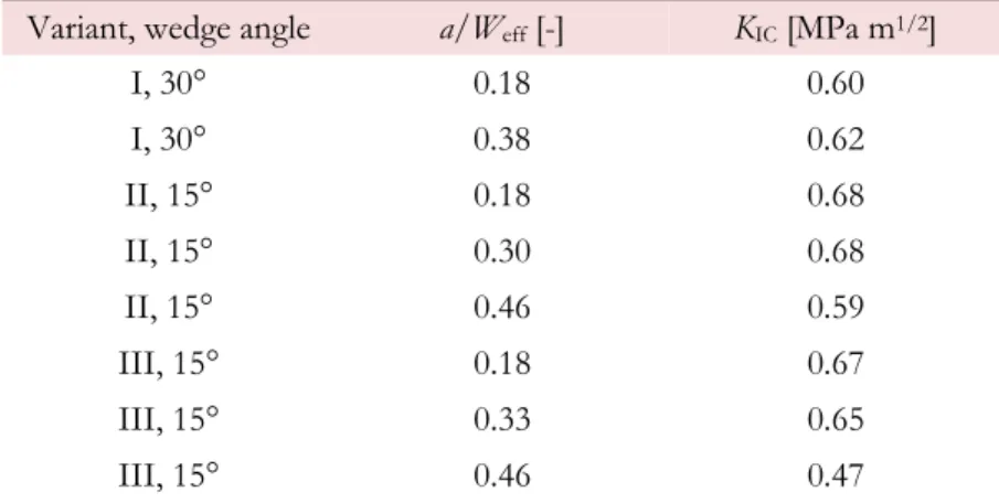
The material and experimental procedure are described in [29]. For evaluation of data in our paper, knowledge about selected input data are needed, therefore the relative initial notch length a/Weff and the maximal value of splitting force
Pspmax are shown in Tab. 3. Note that for I variants the values of SIF were evaluated according to [14] for wedge angle 30° and for all others the new calibration curves were used, see Fig. 4.
Using the classical linear elastic fracture mechanics, the fracture toughness KIC can be worked out on the basis of the initial relative notch length. The following expressions are used:
N I N sp sp
IC K
BP P
K ,1000
1000 ,
max ,
(4)
Using the results (calibration curves for 1000N) presented in Fig. 4, relation between the maximum splitting force Eq. (4) for relative notch length a/Weff, we obtain results of fracture toughness of concrete, the results are shown in Tab. 4. It can be seen, that the values of fracture toughness are within the interval 0.2÷1.4 MPam1/2, see in [1, 9]. The values of fracture
toughness have decreasing tendency when the relative notch length grow, this is in accordance with the results in [34], where for this effect explanation the changes of T-stress values is used.
Variant, wedge angle a/Weff [-] Pspmax [kN]
I, 30° 0.18 7.60
I, 30° 0.38 5.74
II, 15° 0.18 9.80
II, 15° 0.30 7.47
II, 15° 0.46 4.17
III, 15° 0.18 13.68
III, 15° 0.33 9.33
III, 15° 0.46 4.56
Table 3: Variants of evaluated experiments and corresponding wedge angle, and the relative notch length with maximal value of splitting force (both values are mean values from 3 up to 6 measurements, see detail in [29].
Variant, wedge angle a/Weff [-] KIC [MPa m1/2]
I, 30° 0.18 0.60
I, 30° 0.38 0.62
II, 15° 0.18 0.68
II, 15° 0.30 0.68
II, 15° 0.46 0.59
III, 15° 0.18 0.67
III, 15° 0.33 0.65
III, 15° 0.46 0.47
S. Seitl et alii, Frattura ed Integrità Strutturale, 39 (2017) 100-109; DOI: 10.3221/IGF-ESIS.39.11
107
CONCLUSIONS
n this paper, the combinations of wedge splitting and three-point bending load applied on beam-shaped notched specimens are numerically analyzed. The numerically obtain data could be used for evaluation of experimentally obtain data as is shown in example. Based on the numerical results presented here, the following conclusions can be drawn:
The values of the stress intensity factor (KI) have the same trend in the whole range of the relative crack length for specimen variants I, II and III, see Fig. 1.
The values of the T-stress increase with the distance of the two supports on the bottom side of the specimen, varies from negative to positive values with increasing relative crack length (a/Weff), for specimen variants I, II and III.
The values of COD increase in the whole range of the relative crack length (a/Weff) for all variants of the boundary conditions for specimen variants I, II and III.
The variant IIIb has a crack from the bottom part of the specimens, the crack growth is influenced by
combination of the wedge splitting force which in turn leads to crack closure during the load of specimen, see in Fig. 6.
The obtain calibration and compliance functions could be especially usefull for the published advanced model e.g. [8, 16, 20, 32].
ACKNOWLEDGMENTS
he authors acknowledge the support of Czech Sciences foundation project No. 15-07210S and Brno University of Technology Project No. FAST-S-16-3475. The research was conducted in the frame of IPMinfra supported through project No. LM2015069 of MEYS.
REFERENCES
[1] Anderson, T.L., Fracture mechanics fundamentals and applications, CRC Press, (1991). [2] ANSYS: Příručka ANSYS Workbench 2012, Česká technika – nakladatelství ČVUT, (2012).
[3] ASTM E399-90. Standard test method for plane-strain fracture toughness testing of high strength metallic materials. Philadelphia: Amer Soc for Testing and Mater; (1990).
[4] Brühwiller, E., Wittmann, F.H., The wedge splitting test, a new method of performing stable fracture mechanics test, Engineering fracture mechanics, 35 (1990) 117–125.
[5] Cifuentes, H., Karihaloo, D.L. Determination of size-independent specific fracture energy of normal and
high-strength self-compacting concrete from wedge splitting tests, Construction and Building Materials, 48 (2013) 548– 553. DOI: 10.1016/j.conbuildmat.2013.07.062.
[6] Cifuentes, H., Lozano, M., Holusova, T., Medina, F., Seitl, S., Canteli, A., Applicability of a modified compact tension specimen for measuring the fracture energy of concrete, Anales de Mecánica de la Fractura, 32 (2015) 208– 213.
[7] Guinea, G.V., Elices, M., Planas, J., Stress intensity factors for wedge–splitting geometry, Int J Fracture, 81 (1996) 113–124, DOI: 10.1007/BF00033177.
[8] Havlíková, I., Majtánová, R.V., Šimonová, H., Láník, J., Keršner, Z., Evaluation of three-point bending fracture tests of concrete specimens with polypropylene fibres via double-K model, Key Engineering Materials, 592-593 (2014)
185–188, DOI:10.4028/www.scientific.net/KEM.592-593.185.
[9] Karihaloo, L.B., Fracture Mechanics and Structural Concrete, Longman, (1995).
[10] Katzer, J., Domski, J., Optimization of fibre reinforcement for waste aggregate cement composite, Construction and Building Materials 38 (2013) 790–795. DOI: 10.1016/j.conbuildmat.2012.09.057.
[11] Knésl, Z., Bednár, K., Two–parameter fracture mechanics: Calculation of parameters and their values, Institute of Physics of Materials Academy of Science of the Czech Republic, (1998).
I
S. Seitl et alii, Frattura ed Integrità Strutturale, 39 (2017) 100-109; DOI: 10.3221/IGF-ESIS.39.11
108
[12] Korte, S., Boel, V., De Corte, W., De Schutter, G., Static and fatigue fracture mechanics properties of self– compacting concrete using three–point bending tests and wedge–splitting tests. Construction and Building Materials, 57 (2014) 1–8. DOI: 10.1016/j.conbuildmat.2014.01.090.
[13] Leevers, P.S., Radon, J.C., Inherent stress biaxiality in various fracture specimen geometries, Int J Fracture, 19 (1983)
311–325.DOI: 10.1007/BF00012486.
[14] Linsbauer, H.N., Tschegg, E.K., Fracture energy determination of concrete with cube shaped specimens, Zement
und Beton, 31 (1986) 38–40.
[15] Merta, I., Tschegg, E.K., Fracture energy of natural fibre reinforced concrete, Construction and Buildings Materials 40 (2013) 991–997. DOI: 10.1016/j.conbuildmat.2012.11.060.
[16] Pazdera, L., Topolar, L., Simonova, H., Fojtu, P., Smutny, J., Havlikova, I., Kersner, Z., Rodriguezova, V., Determine parameters for double-K model at three-point bending by application of acoustic emission method, Applied Mechanics and Materials, 486 (2014) 151–156. DOI: 10.4028/www.scientific.net/AMM.486.151.
[17] Planas, J., Elices, M., Guinea, G.V., Measurement of the fracture energy using three–point–bend tests: 2 Influence of bulk energy dissipation. Materials and Structures, 25 (1992) 305–312.
[18] RILEM 106, Determination of the fracture energy of mortar and concrete by means of three-point bend tests on
notched beams, (1985) 285–290.
[19] RILEM REPORT 5 Fracture Mechanics, Test Methods for Concrete, (1991).
[20] Ruiz, G., Ortega, J.J., Yu, R.C., Xu, S., Wu, Y., Loading rate effect on the double –K fracture parameters of concrete, 9th International Conference on Fracture Mechanics of Concrete and Concrete Structures, (2016) 1–10.
DOI: 10.21012/FC9.038
[21] Seitl, S., Bermejo, C., Sobek, J., Veselý, V., Two parametr description of crack tip stress fields for wedge splitting test specimen: Influence of wedge angle, Advanced Materials Research, 969 (2014) 345–350.
DOI: 10.4028/www.scientific.net/AMR.969.345.
[22] Seitl, S., Korte, S., De Corte, W., Boel, V., Sobek, J., Veselý, V., Selecting a suitable specimen shape with low constraint for determination of fracture parameters of cementitious composites, Key Engineering Materials, 577–578 (2014) 481–484. DOI: 10.4028/www.scientific.net/KEM.577-578.481.
[23] Seitl, S., Nieto García, B., Merta, I., Wedge splitting test method: Quantification of influence of glued marble plates by two-parameter fracture mechanics, Frattura ed Integrità Strutturale, 30 (2014) 174-181. DOI: 10.3221/IGF-ESIS.30.23.
[24] Seitl, S., Veselý, V., Routil, L., Two–parameter fracture mechanical analysis of a near-crack-tip stress field in wedge splitting test specimens, Computers & Structures, 89 (2011) 1852–1858.
[25] Sobek, J., Veselý, V., Seitl, S., Combination of wedge splitting and bending fracture test- Crack tip stress field and nonlinear zone extent analysis, Advanced Materials Research, 969 (2014) 67–72.
DOI: 10.4028/www.scientific.net/AMR.969.67.
[26] Sobek, J., Veselý, V., Shape and compliance functions of splitting/bending test specimens for determination fracture parameters of quasi-brittle materials, 33rd Spanish Conference on Fracture and Structural Integrity – 33er Encuentro
del Grupo Español de Fractura GEF in: M.R. Elizalde González, A. Martín Meizoso, J.M. Martínez Esnaola, I. Ocaña Arizcorreta (Eds.) (Anales de Mécanica de la Fractura volumen 33), Donostia‐San Sebastián, Spain, (2016).
[27] Tada, H., Paris, P.C., Irwin, G.R., The stress analysis of crack handbook, third ed., The American Society of
Mechanical Engineers Three Park Avenue, New York, (2000).
[28] Veselý, V., Frantík, P., Sobek, J., Malíková, L., Seitl, S., Multi-parameter crack tip stress state description for evaluation of nonlinear zone width in silicate composite specimens in component splitting/bending test geometry, Fatigue and Fracture of Engineering Materials and Structures, 38(2) (2015) 200–214. DOI: 10.1111/ffe.12170. [29] Veselý, V., Merta, I., Šimonová, H., Schneemayer, A., Seitl, S., Keršner, Z., Component wedge-splitting/bending test
of notched specimens with various crack-tip constraint conditions: Experiments and simulations, 9th International
Conference on Fracture Mechanics of Concrete Structures FraMCoS-9, (2016) 1–12.DOI: 10.21012/FC9.086.
[30] Veselý, V., Sobek, J., Frantík, P., Štafa, M., Šestáková, L., Seitl, S. Estimation of the zone of failure extent in quasi-brittle specimens with different crack-tip constraint conditions from stress field, Key Engineering Materials, 592-593 (2014) 262–265. DOI: 10.4028/www.scientific.net/KEM.592-593.262.
[31] Veselý, V., Sobek, J., Šestáková, L., Frantík, P., Seitl, S., Multi-parameter crack tip stress description for estimation of fracture proces zone extent in silicate composite WST specimens, Frattura ed Integrita Strutturale, 7(25) (2013) 69– 78. DOI: 10.3221/IGF-ESIS.25.11.
S. Seitl et alii, Frattura ed Integrità Strutturale, 39 (2017) 100-109; DOI: 10.3221/IGF-ESIS.39.11
109
DOI: 10.1016/j.engfracmech.2016.03.036
[33] Williams, M.L., On the stress distribution at the base of stationary crack, ASME Journal of Applied Mechanics, 24 (1957) 109–114.
![Figure 1: Considered variants for the combined bending/splitting configurations, taken from [29].](https://thumb-eu.123doks.com/thumbv2/123dok_br/18391969.357664/2.892.92.803.493.1070/figure-considered-variants-combined-bending-splitting-configurations-taken.webp)
![Table 2: Nominal variant dimensions and test geometry parameters, taken from [29].](https://thumb-eu.123doks.com/thumbv2/123dok_br/18391969.357664/3.892.92.800.192.349/table-nominal-variant-dimensions-test-geometry-parameters-taken.webp)