João Artur Marcelino Pacheco
Master of SciencePerformance Evaluation of Class A LoRa
Communications
Dissertação para obtenção do Grau de Mestre em
Engenharia Electrotécnica e de Computadores
Orientador: Rodolfo Alexandre Duarte Oliveira, Prof. Auxiliar c/ Agre-gação,
NOVA University of Lisbon
Júri
Presidente: Doutor João Carlos da Palma Goes
Arguente: Doutor Francisco António Taveira Branco Nunes Monteiro Vogal: Doutor Rodolfo Alexandre Duarte Oliveira
Performance Evaluation of Class A LoRa Communications
Copyright c João Artur Marcelino Pacheco, Faculdade de Ciências e Tecnologia, Univer-sidade NOVA de Lisboa.
A Faculdade de Ciências e Tecnologia e a Universidade NOVA de Lisboa têm o direito, perpétuo e sem limites geográficos, de arquivar e publicar esta dissertação através de exem-plares impressos reproduzidos em papel ou de forma digital, ou por qualquer outro meio conhecido ou que venha a ser inventado, e de a divulgar através de repositórios científicos e de admitir a sua cópia e distribuição com objetivos educacionais ou de investigação, não comerciais, desde que seja dado crédito ao autor e editor.
Este documento foi gerado utilizando o processador (pdf)LATEX, com base no template “novathesis” [1] desenvolvido no Dep. Informática da FCT-NOVA [2].
Acknowledgements
First and foremost I would like to express my deepest gratitude to my supervisor, Professor Rodolfo Oliveira, whose guidance and deep knowledge in the subject matter were crucial in the development of this work. As my teacher and mentor he has given more me useful guidance, insightful comments, and considerable encouragements than I could ever give him credit for here. I would like to show my gratitude to António Furtado who was always willing to help and guide me at any given time. His previous work was an essential part of this thesis.
This work would not be possible without the financial support provided by the Projects InfoCent-IoT (POCI-01-0145-FEDER-030433) and CoSHARE (LISBOA-01-0145-FEDER-0307095 - PTDC/EEI-TEL/30709/2017), funded by Fundo Europeu de Desenvolvimento Regional (FEDER), through Programa Operacional Regional LISBOA (LISBOA2020), and by national funds, through Fundação para a Ciência e Tecnologia (FCT).
Last but not least, i would like to show my unending thankfulness to my family and friends, especially to my parents and sister, who always stood by my side. Their love and guidance are with me in whatever I pursue. I can not express in words how thankful I am for all the opportunities they provided me.
A b s t r a c t
Recently, Low Power Wide Area Networks (LPWANs) have attracted a great interest due to the need of connecting more and more devices to the so-called Internet of Things (IoT). This thesis explores LoRa’s suitability and performance within this paradigm, through a theoretical approach as well as through practical data acquired in multiple field campaigns. First, a performance evaluation model of LoRa class A devices is proposed. The model is meant to characterize the performance of LoRa’s Uplink communications where both physical layer (PHY) and medium access control (MAC) are taken into account. By admitting a uniform spatial distribution of the devices, the performance characterization of the PHY-layer is studied through the derivation of the probability of successfully decoding multiple frames that were transmitted with the same spreading factor and at the same time. The MAC performance is evaluated by admitting that the inter-arrival time of the frames generated by each LoRa device is exponentially distributed. A typical LoRaWAN operating scenario is considered, where the transmissions of LoRa Class A devices suffer path-loss, shadowing and Rayleigh fading. Numerical results obtained with the modeling methodology are compared with simulation results, and the validation of the proposed model is discussed for different levels of traffic load and PHY-layer conditions. Due to the possibility of capturing multiple frames simultaneously, the maximum achievable performance of the PHY/MAC LoRa scheme according to the signal-to-interference-plus-noise ratio (SINR) is considered. The contribution of this model is primarily focused on studying the average number of successfully received LoRa frames, which establishes a performance upper bound due to the optimal capture condition considered in the PHY-layer. In the second stage of this work a practical LoRa point-to-point network was deployed to characterize LoRa’s performance in a practical way. Performance was assessed through data collected in the course of several experiments, positioning the transmitter in diverse locations and environments. This work reports statistics of the received packets and different metrics gathered from the physical-layer.
R e s u m o
No passado recente, a necessidade de conectar cada mais dispositivos à chamada Inter-net das Coisas, despertou um interesse por redes de baixa potência e longa distância (LPWANs). Esta dissertação explora a aptidão e desempenho da tecnologia LPWAN LoRa, tanto através de uma abordagem teórica, bem como da análise de dados práticos recolhidos em várias campanhas. Primeiramente é proposto um modelo de avaliação de desempenho de dispositivos LoRa de classe A. O modelo foi desenvolvido com o propósito de caracteri-zar o desempenho do Uplink LoRa, considerando a camada física bem como a camada de controlo de acesso ao meio. Admitindo que os dispositivos estão uniformemente espacial-mente distribuídos, a caracterização do desempenho da camada PHY é estudada através da derivação da probabilidade de descodificar com sucesso vários pacotes enviados em simultâneo e usando o mesmo fator de espalhamento. A análise do desempenho da camada MAC é realizada supondo que o tempo entre pacotes é exponencialmente distribuído. É considerado um cenário típico de operação LoRaWAN, onde os sinais transmitidos pelos dispositivos LoRa classe A são afetados por atenuação, zonas de sombra e desvanecimento de Rayleigh. Os resultados numéricos obtidos através da metodologia exposta no modelo são comparados com resultados simulados, ademais, a validação do modelo proposto é discutida segundo diferentes níveis de carga na rede e condições na camada PHY. De-vido à possibilidade de multi-captura simultânea, os resultados representam o máximo de desempenho alcançável num esquema PHY/MAC LoRa em relação a um rácio entre sinal e ruindo mais interferência (SINR). A principal contribuição deste modelo reside no estudo do número médio de pacotes LoRa recebidos com sucesso, pelo que considerando a condição óptima de captura definida na camada PHY, representa um limite superior de desempenho. Na segunda parte deste trabalho, é operacionalizada uma rede ponto a ponto de forma a caracterizar na prática o desempenho das comunicações LoRa. O desempenho é avaliado através de dados recolhidos no curso de várias experiências, no qual o transmissor foi posicionado em diversos locais e ambientes. São reportados os dados recolhidos, bem como estatísticas dos pacotes recebidos e diferentes métricas da camada física e de controlo de acesso ao meio.
C o nt e nt s
List of Figures xvii
List of Tables xix
Glossary xxi Acronyms xxiii 1 Introduction 1 1.1 Introduction. . . 1 1.2 Motivation . . . 1 1.3 Objectives . . . 2 1.4 Contributions . . . 2 1.5 Outline . . . 3
2 State of the Art 5 2.1 Cyber Physical Systems . . . 5
2.2 Internet of Things (IoT) . . . 6
2.3 Heterogeneity and interoperability of information . . . 9
2.3.1 Gateway . . . 9
2.4 Application Protocols . . . 10
2.4.1 Web Protocols . . . 11
2.4.2 Low Power Application Protocols . . . 12
2.5 Network Layer Specifications . . . 15
2.5.1 Low Power Wide Area Network . . . 15
2.5.2 Licensed and Unlicensed LPWANs . . . 16
2.5.3 Low Power Wide Area Network Specifications . . . 16
2.6 Cloud Computing. . . 25 2.7 Databases . . . 26 2.7.1 Relational Databases . . . 26 2.7.2 Non-Relational Databases . . . 27 2.7.3 Overview . . . 27 2.8 Data analytics . . . 28
2.8.1 Types of Analytics . . . 28
2.8.2 Analytic methods. . . 29
2.9 IoT architectures . . . 31
2.9.1 Service Oriented Architecture (SOA) . . . 33
2.9.2 Distributed Internet-like Architecture for Things (DIAT) . . . 34
2.9.3 Semantic Service Oriented Architecture (SSOA) . . . 38
3 LoRa and LoRaWAN 41 3.1 LoRa. . . 41 3.1.1 Encoding . . . 41 3.1.2 Spreading Factor . . . 45 3.1.3 Time on Air. . . 47 3.2 LoraWan . . . 48 3.2.1 Topology . . . 48 3.2.2 Encryption . . . 49
3.3 Message Formats in Class A Devices . . . 50
3.3.1 PHY Message Formats . . . 50
3.3.2 MAC Message Formats . . . 50
3.4 EU 863-870 MHz ISM Band . . . 54
3.4.1 Regulatory Limitations . . . 55
3.4.2 Preamble Format . . . 56
4 Theoretical LoRa Performance 59 4.1 Uplink PHY Performance Model . . . 59
4.2 PHY/MAC Uplink Performance of Class A LoRa Networks . . . 63
4.2.1 Medium Access Control . . . 64
4.2.2 Network Assumptions . . . 65
4.2.3 Physical Layer . . . 68
4.2.4 Joint PHY/MAC Performance . . . 72
4.3 Performance Evaluation . . . 73
4.3.1 Model Validation . . . 74
4.3.2 MAC Layer . . . 77
4.3.3 PHY Layer . . . 79
4.3.4 Joint MAC-PHY Model . . . 80
5 Measured LoRa Performance 85 5.1 LoRa Node . . . 85
5.2 LoRa Gateway . . . 87
5.3 Test Sites . . . 88
5.4 Performance evaluation . . . 91
C O N T E N T S
6.1 Final Remarks . . . 97 6.2 Future Work . . . 98
Bibliography 101
A Network Server GUI 109
L i s t o f F i g u r e s
2.1 IoT layer architectures [4]. . . 7
2.2 IoT three layers architecture [76]. . . 8
2.3 IoT five layer architecture [31]. . . 8
2.4 Standardizations in the IoT plane. . . 10
2.5 HTTP client-server communication [43]. . . 11
2.6 M2M protocols usage versus standardization (adapted from [42]). . . 14
2.7 Data rate vs range of radio communication technologies [38]. . . 16
2.8 LoRaWAN stack [74]. . . 18
2.9 LoRaWAN network topology [74]. . . 18
2.10 LoRaWAN end device classes [66]. . . 19
2.11 Sigfox network coverage in Europe [64]. . . 20
2.12 Sigfox network structure [65]. . . 22
2.13 NB-IoT modes of operation [38]. . . 23
2.14 NB-IoT network structure [12]. . . 25
2.15 Overview of the central elements of cloud computing (adapted from [70]). . . 26
2.16 Data analytic methods [36]. . . 30
2.17 Four-layer service oriented architecture. . . 34
2.18 DIAT architecture [52]. . . 35
2.19 Human object contextual vector [52]. . . 36
2.20 Non-human object contextual vector [52]. . . 37
2.21 DIAT architecture BDIP mode [52]. . . 38
2.22 DIAT security management module [52]. . . 38
2.23 Semantic IoT architecture [72]. . . 39
2.24 Semantic gateway as service [72]. . . 39
3.1 Payload symbol number increase introduced by block coding. . . 43
3.2 (a) Symbol rate halves with every iteration of Spreading Factor. (b) Period doubles. . . 45
3.3 Payload symbol number increase introduced by block coding. . . 46
3.4 Spreading factor effect in transmission time. . . 48
3.5 Protocol stack of LoRaWAN network components [35]. . . 49
3.7 Downlink PHY message structure [67]. . . 50
3.8 Packet structure of LoRaWAN message [67].. . . 50
3.9 Frame control field contents [67]. . . 53
3.10 Sub divisions of the 868-870 MHz sub-band [2]. . . 54
3.11 De-chirped LoRa signal [32].. . . 57
4.1 Network layout [23]. . . 62
4.2 Coverage probability.. . . 62
4.3 Comparison of Shadowing LogNormal and Gamma approximation distributions CDF for different values of σξ. . . 74
4.4 Success probability of PHY layer given ncconcurrent transmissions considering different fading combinations. . . 75
4.5 Simulated and theoretical access probability for different network sizes and frames per time unit.. . . 76
4.6 Theoretical and simulated probability of success given nc concurrent transmis-sions. . . 77
4.7 Probability of observing c = 1, 2, 3, 4, 10 concurrent transmissions. . . . 78
4.8 Probability of observing c concurrent transmissions. . . . 78
4.9 Path loss effect on signal to noise ration.. . . 79
4.10 Individual success probability in different sized networks. . . 80
4.11 Success probability given nccollisions as a function of the access probability. 81 4.12 (a) Successful frame reception probability (P[S]) for different path loss scenarios, α; (b) Average number of successful received frames (E[Nrx]) for different path loss scenarios, α. . . . 82
4.13 (a) Successful frame reception probability (P[S]) for different shadowing scenar-ios, σξ; (b) Average number of successful received frames (E[Nrx]) for different shadowing scenarios, σξ. . . 82
4.14 (a) Successful frame reception probability (P[S]) for different path loss scenarios, α; (b) Average number of received frames (E[Nrx]) for different values of b (for α = 2.01 and σξ= 0.69). . . . 83
5.1 Assembled node. . . 86
5.2 Lora gateway. . . 87
5.3 Gateway location. . . 88
5.4 Test sites locations.. . . 89
5.5 Gateway position relative to each test site, and the respective test sites elevation above see level. . . 91
5.6 Success probability for each test site. . . 94
L i s t o f Ta b l e s
2.1 Overview comparison of computing methods [60]. . . 6
2.2 Comparison of characteristics of transport layer technologies in IoT. . . 9
2.3 Overview comparison of low power application protocols. . . 12
2.4 Overview of LPWAN technologies. . . 24
3.1 LoRa error detecting and correcting capabilities [41]. . . 44
3.2 Binary to Gray Coding conversion example. . . 45
3.3 Coding Rate influence on bit rate with a bandwidth of 125 kHz. . . 46
3.4 Bandwidth influence on bit rate with a code rate of 45. . . 46
3.5 MAC message types [67]. . . 51
3.6 Data stored in an end-device after activation [67].. . . 51
3.7 FPort field values [67]. . . 52
4.1 Path loss exponent in different environments [40] . . . 60
4.2 Noise floor values for all bandwidths. . . 61
4.3 Receiver sensitivity and SNR threshold for different spreading factors with a bandwidth of 125 kHz and code rate of one. . . 61
5.1 Test site geographic locations and approximate distance to the gateway. . . . 88
5.2 Packet Error Rate (PER) for each spreading factor per test site. . . 92
5.3 Average Signal to noise ratio for each spreading factor per test site.. . . 94
G l o s s a r y
Backhaul The intermediate links between the backbone network and its smaller sub-networks.
Chip Frequency jump that determine how the data is encoded onto the chirps. Chirp A sweep signal, i.e a signal whose frequency changes at a fixed rate, it
constantly increases (up-chirp) or decreases (down-chirp).
Hop Each hop represents a portion o the path between a source and destina-tion.
Link budget An accounting of all the gains and losses between a transmitter and a receiver.
Noise floor The resulting signal from the sum of all unwanted interferences and noise sources.
Sensitivity The minimum magnitude of an input signal required, so that it can be successfully received.
Symbol A representation of one or more bits of data.
Throughput Data transfer rate, the quantity of data transfered between two distinct entities or the amount of computed data in a given time interval.
Ac r o ny m s
3GPP Third Generation Partnership Project.
ABP Activation by Personalization.
ACID Atomicity, Consistency, Isolation and Durability.
ADR Adaptive Data Rate.
AES Advanced Encryption Standard.
AGNES Agglomerative Nesting.
AMQP Advanced Message Queuing Protocol. API Application Programing Interface.
BD Big Data.
BI Business Intelligence.
BPSK Binary Phase Shift Keying.
BS Base Station.
CAP Consistency, Availability and Partitioning.
CEPT European Conference of Postal and Telecommunications Administra-tions.
CIoT Cellular Internet of Things.
CLARANS Clustering Large Applications based on RANdomized Search. CoAP Constrained Application Protocol.
CoRE Constrained RESTful Environments.
CPS Cyber Physical System.
CPU Central Processing Unit.
CRC Cyclic Redundancy Check.
CRUD Create Read Update Delete.
CSS Chirp Spread Spectrum.
CVO Composite Virtual Object.
DIAT Distributed Internet-like Architecture for Things.
DL Downlink.
DNS-SD Domain Name System - Service Discovery.
DS Direct Sequence.
DSL Digital Subscriber Line.
DSSS Direct Sequence Spread Spectrum. DTLS Datagram Transport Layer Security.
EARFCN E-UTRA Absolute Radio Frequency Channel Number.
ED End Device.
ERC European Radio-communications Committee. ERP Effective Radiated Power.
ETSI European Telecommunications Standards Institute.
FEC Forward Error Correction.
FH Frequency Hopping.
FHDS Frequency Hopping Direct Sequence Hybrid.
GSM Global System for Mobile Communications.
HDFS Hadoop Distributed File System. HTTP Hypertext Transfer Protocol.
IaaS Infrastructure as a System.
IEEE Institute of Electrical and Electronics Engineers. IETF Internet Engineering Task Force.
iid independent and identically distributed. IoT Internet of Things.
IPSec Internet Protocol Security. ISM Industrial Scientific and Medical. IT Information Technology.
KNN K-Nearest Neighbor.
LBT Listen Before Talk. LHC Large Hadron Collider.
AC RO N Y M S
LoRa Long Range.
LPWAN Low Power Wide Area Network. LTE Long-term Evolution.
M2M Machine to Machine.
MAC Medium Access Control. MIC Message Integrity Code.
MQTT Message Queuing Telemetry Transport.
NB-IoT Narrow Band-Internet of Things. NFC Near Field Communication.
NS Network Server.
OFDMA Orthogonal Frequency Division Multiple Access. OTAA Over-The-Air-Activation.
PaaS Platform as a System.
PAM Partitioning Around Medoids. PDF Power Density Function. PDP Policy Decision Point. PEP Policy Enforcement Point. PER Packet Error Rate.
PM Policy Manager.
PR Policy Repository.
PSD Power Spectral Density.
QoS Quality of Service.
QPSK Quadrature Phase Shift Keying.
RB Resource Block.
REST Representational State Transfer. RFID Radio-Frequency IDentification. RFU Reserved for Future Use.
RSSI Received Signal Strength Indicator.
RV Random Variable.
SASL Simple Authentication and Security Layer.
SC-FDMA Single Carrier - Frequency Division Multiple Access. SCTP Stream Control Transmission Protocol.
SF Spreading Factor.
SGS Semantic Gateway as Service.
SINR Signal to Interference plus Noise Ratio.
SL Service Layer.
SM Service Management.
SNR Signal to Noise Ratio.
SOA Service Oriented Architecture. SQL Structured Querying Language.
SSL Secure Sockets Layer.
SSOA Semantic Service Oriented Architecture.
SVM Support Vector Machine.
TCP Transmission Control Protocol. TLS Transport Layer Security.
UDP User Datagram Protocol.
UL Uplink.
UNB Ultra Narrow Band.
URI Uniform Resource Identifier.
VO Virtual Object.
VOL Virtual Object Layer.
WAN Wide Area Network.
WoT Web of Things.
WSN Wireless Sensor Network.
C h a p t e r
1
I nt r o d u c t i o n
1.1
Introduction
For quite some time, the Cyber Physical System (CPS) concept has been a staple technol-ogy in automated industries. CPSs consist of an amalgamation of physical entities and computational elements intertwined such that their components are able to interact with each other, adapt and a react accordingly to their environment. This requiring increasing autonomy, adaptability and reliability.
With technological advances the Internet of Things (IoT) paradigm emerged and ex-panded the concept of connection and communication of virtual and physical entities to the Internet. The endless possibilities of applications, combined with cheap and readily available hardware and software IoT solutions, allowed IoT devices to be spread over all sorts of industrial and commercial sectors. Currently, the number of operational IoT systems is steadily increasing by the day. Naturally it is an highly researched theme and with new solutions constantly being presented, Internet of Things is quickly turning into one of the fastest growing global markets.
1.2
Motivation
Internet of Things is still a relatively recent concept, but its potential is too high. By improving the connectivity capabilities between computational and physical devices, this paradigm extended Internet connectivity from typical devices (laptops, smart phones, etc.) to everyday objects. This opened the doors to an extensive amount of applications outside the industrial and manufacturing environment. IoT technology is being used from small scale scenarios like smart homes and farms to energy management, transportation or even
metropolitan scale deployments.
IoT greatly enhanced data gathering mechanisms, thus enabling researchers to rapidly gather large amounts of information and decreasing the time necessary to ascertain mean-ingful conclusions like hidden correlations among a system, behavioral patterns, and social trends. Despite of this, the IoT arena is still characterized by a lack of standardization, making interoperability of devices a bigger challenge. Researchers are actively making efforts towards a future, where devices can be seamlessly integrated into a network and provide ubiquitous computing. LoRa is one of the most prominent technologies for long range connectivity in IoT sytems. A such, this work tries to answer two main questions. First, how would the protocol perform if the gateway had the capacity to simultaneously decode multiple frames, without any additional costs on the end devices. Secondly, what can be expected, performance wise, from the currently available LoRa devices.
1.3
Objectives
The objectives to be achieved in this dissertation are as follows:
O1. In a first step it is required to understand the fundamentals of LoRa’s PHY and MAC layer. The goal is to identify LoRa’s literature and understand its design and operation to identify and filter important information to be used in this work; O2. Given the importance of LoRa networks, this work aims to quantify the gain of
performance when the gateway is capable of decoding multiple packets at the same time (instead of decoding at most one). This is the main goal of this work, which encompasses the design of a theoretical framework to model the physical and the MAC layers in a cross-layered design. The performance assessment is based on the comparison of the numerical results (obtained with the theoretical model) with simulation results;
O3. This objective targets the performance evaluation of a practical LoRa system. This includes the acquisition of LoRa devices, the study of their programming interfaces, the design of realistic and diversified experimental scenarios, and at a final phase the gathering of LoRa communications’ statistics and their statistical analysis.
1.4
Contributions
Regarding the contributions of this work, we list the following ones:
C1. A brief overview of IoT and LoRa networks was written, which supports the funda-mentals to study LoRa networks;
C2. A theoretical model is proposed to compute the upper bound of LoRa’s performance when the gateway is capable of decoding multiple packets at the same instant. The
1 . 5 . O U T L I N E
theoretical model was compared with simulated results to evaluate its accuracy. This contribution was also reported in a conference paper that is currently under review in a Q1 Scimago conference (submitted to the 15th International Wireless Communications and Mobile Computing Conference, Tanger, Marrocos (IWCMC 2019) - the paper is copied in Annex I);
C3. A comprehensive study of the hardware acquired to achieve the objective O3 in order to design and operationalize multiple tests to be conducted at different scenarios. This contribution has to do with the practical data obtained with LoRa devices, which is discussed in this dissertation and will be worked to prepare a technical paper in the near future.
1.5
Outline
This work aims to explore currently available Internet of things technologies and architec-tures as well as disclose LoRa’s suitability in this context.
Chapter 2 presents a brief explanation of the IoT paradigm, followed by a general description of the some technologies and techniques that support it.
Chapter 3 is aligned with the objective O1. A detailed explanation of LoRa’s protocol is provided. This involves the specification of techniques employed by LoRa, such as the methods used to decode and or recover data from a packet that suffered transmission errors, the coding scheme, the methodology of increasing signals’ resilience to noise, and its effect on the time on air of a packet. LoRaWAN’s MAC layer is also specified. It encompasses a clarification on the structure of both uplink and downlink messages, the types of messages available and the protocols intricacies, such as the joint procedures between end devices and the gateway when the former attempts to join the network. Additionally, Chapter 2 contains a brief report on the transmission limitations imposed by the regulatory bodies. Chapter 4 describes the work to address the objective O2. It proposes a theoretical model to characterize LoRa’s uplink performance. The proposed model is be divided into two stages: model description, and performance evaluation. The former provides a detailed description of the considered network scenario, PHY layer performance characterization, MAC layer access probability, as well as the performance characterization of the joint PHY and MAC layers. The network scenario includes the network structure, nodes’ spatial distribution and propagation conditions, namely the path loss, the modeling of shadowing and Rayleigh fading along with the modeling of their composite effect. The PHY layer section specifies how the performance characterization is accomplished through the probability of successfully decoding a frame. Regarding the MAC layer, the access behaviour is described as a Poisson process considering the network load. The joint PHY/MAC performance contains the process used to describe the success probability when accounting for both the MAC and PHY layers. The contribution of this model is primarily focused on studying the average number of successfully received LoRa frames, which
establishes a performance upper bound due to the optimal capture condition considered in the PHY-layer.
Chapter 5 describes the practical assessment tests and results aligned with objective O3. Several tests are described considering that the transmitter is placed at different locations to evaluate LoRa’s link performance in different propagation environments. The data gathered in real time is then statistically treated to determine the achieved performance. Finally, Chapter 6 presents final remarks and discusses different paths to extend this work in future efforts.
C h a p t e r
2
S t a t e o f t h e A r t
2.1
Cyber Physical Systems
Cyber Physical Systems (CPSs) represent systems where the computation process and physical data are intrinsic, being characterized as a boundless network of devices, compu-tational resources, applications, and services interconnected amongst themselves. CPSs are usually managed through the use of a broad spectrum of sensors, actuators and com-munication topologies. This technology allows to hypothesize a future where a system can monitor physical information, while simultaneously analyzing such information in its cybernetic layer. This grants the ability to react accordingly and preferably in real time. All in all, despite the advantages this trend brings, a new set of problems arise. A system abiding by this specifications inherently consumes and generates huge amounts of data, which can possibly be problematic due to limitations akin with current hardware processing power and available storing space. Fortunately, with the exponential growth of Internet of Things (IoT) systems and Cloud computing, is possible to outline these adversities.
Considering all the characteristics previously discussed, a CPS has three main requisites to fulfill:
1. Support an intense rate of computation;
2. Store and analyze extensive influxes of information;
3. Enable continuous access to all stored information, through the means of a graphical user interface.
All these three demands can be met through a blend of cloud computing and a wide band connection (IoT) to the system in question. The IoT layer is seen as the mean to enable sensors and actuators integration to the internet. Cloud processing is one of several
methods of computation compared in Table 2.1. An alternative to cloud computing is Cluster computing, which is essentially a form of distributed computation. The process is shared by a multiplicity of computers and storing apparatus, interconnected in order to convey to an user the illusion of it being run a single device. Naturally, the processing capabilities are tied to the number of machines that constitute the network. According to the study [60] the capabilities of a system that employs cluster processing is directly proportional to the number of CPUs used, which makes this paradigm quite expensive to operate. Grid computing consists of several computers interconnected in order to complete a task. The key difference is this paradigm reliance on a control software designed to split a complex task into more manageable steps. Each of those subdivisions is then assigned to a set of computers, members of the network. This technology has been implemented in some Wireless Sensor Networks (WSNs), like the solution described in [28], but its use is only expedient in a system whose processes hold a level of complexity such that it as to be distributed amongst different computers. In an environment where the priority is to guarantee the processing of high data influxes, Cloud computing presents itself as a cheaper and easier to implement archetype.
Cluster Computing Grid Computing Cloud Computing
Loose-coupling No Both Yes
Resource Handling Centralized Distributed Both
Application/
Service Oriented Application Both Service
Hardware Commodity Commodity Mixed
Up Front Cost Medium Medium Low
I/O Performance Low Low Medium
Rapid Elasticity No No Yes
Table 2.1: Overview comparison of computing methods [60].
As a result of the combined low cost and high flexibility, Cloud computing is an important technology when scalability is taken into account.
Clouds solutions and data analytics techniques will be addressed in further detail in Sections 2.6 and2.8.
2.2
Internet of Things (IoT)
In a nutshell, IoT constitutes the networking structure of a cyber physical system, for information transfer purposes. Its basic principle is to allow autonomous and secure connections to achieve data exchanges between physical world devices and applications, acting as a link that connects the physical and virtual world. As a whole it is a compound of objects, sensors, communication infrastructures, computational and processing units, decision making, and action mechanisms [31].
2 . 2 . I N T E R N E T O F T H I N G S ( I O T )
This concept forces IoT to be capable of connecting a endless number of heterogeneous objects over the Internet, meaning its architecture must be as flexible as it can be. Figure 2.1displays several adopted models.
Figure 2.1: IoT layer architectures [4].
The three layers architecture, illustrated in Figure2.2, is the simplest of all four models. In [76] the purpose of each layer is defined in the following manner. The perception layer is responsible for collecting and capturing data. It should perceive the devices that compose it, virtualize them into heterogeneous objects and feed their information to the upper layer. In a perfect scenario this layer should be capable of integrating every apparatus on the network. The challenge is to make it capable of perceiving and recognizing the maximum number of devices, using the least amount of power, and do that in an economic way. The network layer has the task of enabling long distance exchanges of the information, recalled by the previous layer, and its computation. The computation is usually done in a cloud environment as it is effective and cheap. Lastly, there is the application layer whose main purpose is service discovery and arrangement for communities or clients, where the information collected by the system is shared and treated accordingly. In a system designed to read temperature and humidity levels, this layer is the one that conveys sensors readings to the user, on demand. Given the abundance of networking technologies the exchange of information from the network layer to the application layer can be problematic as there is not a market standard and it is impossible to implement every protocol. Solutions like gateways have been designed to counterbalance this situation, but more or less some sacrifices have to be made, depending on the target application.
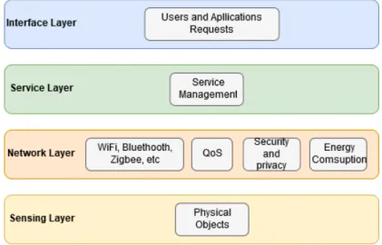
The five layer architecture presented in Figure2.3 is an evolution of the simpler form that adds more abstraction to the IoT model[4]. The perception and application layers remain identical and act as described earlier. The object abstraction layer, also known as transport layer transfers the information collected from the sensors (object perception layer) to the service management layer in a secure manner. Data can be exchanged through a plethora of protocols like NFC, RFID, Bluetooth, ZigBee, etc.. Service Management or Middleware layer stores, analyses, and processes huge chunks of data using technologies such as databases and cloud computing. As the name implies, this layer also associates services to user’s requests. The Business layer oversees and manages all the other layers. Quality of service is reinforced at this level through comparison of real and expected layer
Figure 2.2: IoT three layers architecture [76].
outputs. Additionally, it handles decision making based on big data (BD) analysis and business models strategies like data organization and visual representation (statistical graphs, flowcharts, plots, etc.).
The five layer architecture is able to answer IoTs demands and offers enough flexibility to be tweaked for different applications, resulting in slight variations as illustrated in Figure 2.1, regardless the basics of each layer remains the same and the fundamental functions (identification, sensing, communication, computation, services and semantics) are always
present.
2 . 3 . H E T E RO G E N E I T Y A N D I N T E RO P E R A B I L I T Y O F I N FO R M AT I O N
2.3
Heterogeneity and interoperability of information
2.3.1 Gateway
One of the core points of a wireless sensor network is the gateway. It acts as an intermediary between sensors and the Internet, a process called hub-and-spoke model [15]. Translation of protocols for encryption, processing, filtration and maintenance of information exchanged by the system are all integral responsibilities of this element [68]. The absence of a consensus or standard regarding communication between sensors and the system in which they are to be integrated, impose a high level of complexity on the gateway, from a functional stand point. Furthermore the idea of a standard communication protocol is very questionable in an IoT environment, the vast extent of possible applications make it almost impossible to extend a single protocol for all types of applications [43]. All this implies that the heterogeneity of an IoT system requires the ability to establish communication with the biggest array of sensors, and the gateway has to offer support for a substantial number of protocols.
The challenge lays in the fact that despite the abundance of available technologies, none is disposable, because each one has specific features that make them more or less appropriate, depending on the specifics of each application.
Features Technologies
RFID NFC Zigbee Bluetooth
Peak distance 3-10 m 10 cm 100 m 10-100 m Data rate 640 kbps 106-424 kbps 250 kbps <1 Mbps Capability Identifying, Storing, Interacting
Interacting Secure sharing of data Sharing, Identifying Used in Logistics, Transportation, Retail, Payments Smart phones, Access control, Contactless payments Industrial controls, Digital Agriculture Retail, Healthcare, Transportation
Table 2.2: Comparison of characteristics of transport layer technologies in IoT.
In Table 2.2, adapted from [15], it is possible to observe the different applicabilities of each technology. The authors of [70] reinforce this idea stating that RFID and NFC are very comparable at an application level, although in the context of device-to-device communication, the later manifests an easier and more intuitive to implement. On the other hand the study also points the importance that Zigbee has in the home automation market. It offers consumers unprecedented control and choice in this environment by providing standard interfaces for lighting control, motorization, security, etc... Taking into account that all of these protocols belong to the IoT communication/transport layer and already cause interoperability problems, if all layers of such system are taken in account,
the spectrum of choice possibilities broadens significantly, greatly increasing this issue. For example, according to [4], at the application level, some of the efforts of standardization also include lightweight data protocols, such as the Message Queuing Telemetry Transport (MQTT), Constrained Application Protocol (CoAP), Advanced Message Queuing Protocol (AMQP), and others, summarized in Figure 2.4, extracted from [4].
Figure 2.4: Standardizations in the IoT plane.
All these initiatives increase lack of interoperability amongst sensors. In [72] it is men-tioned that although the IoT domain is scattered between low powered protocols (ZigBee, Bluethooth) and traditional ones (WiFi, Ethernet), standardization can be achieved by assembling hardware with the required components. In other words, this concept may be implemented through different device configurations including but not limited to a microprocessor equipped with communication modules.
Despite the aforementioned, the compatibility problem is still very relevant regarding the application level.
2.4
Application Protocols
In the last section it was established that the biggest challenge haunting WSNs integration is the broad spectrum of protocols available. For the sake of better understanding this problem it is necessary to recognize the options offered in the marketplace.
Application protocols run over the application layer of an IoT system. This layer is responsible for providing customers their requested services, like getting temperature sensor measurements to a customer owned software, on request. It covers numerous markets such as smart home, smart building, agriculture, transportation, industrial automation and smart healthcare [31], whereby the choice of protocol is determined in accordance with the demands imposed by industry where the system is going to operate.
2 . 4 . A P P L I C AT I O N P RO T O C O L S
2.4.1 Web Protocols
It is broadly accepted that due to the energy constraints of a sensor network, the best way to establish communication is with a lightweight message protocol, like those mentioned in the last chapter, claim backed by the wide array of projects employing or acknowledging such technologies [4,42,68,72].
Figure 2.5: HTTP client-server communication [43].
The authors of [43] argued for an alternative solution, instead of relying on traditional IoT protocols, they introduce the concept of Web of Things (WoT). By re-using the existing World Wide Web infrastructure, and web protocols (HTTP) the problem of interoperability can be resolved, although the use of these protocols brings another problem to table, web latency. Time of response can be detrimental to a network that rely on real time action/reaction interactions. Unfortunately, this latency is affected by a number of different factors but mainly on the distance between the client and the server combined with the HTTP and its transport layer protocol (TCP) faults. HTTP incurs several round trips to perform an action, while TCP has a three way handshake system (figure 2.5) required to open a connection for every HTTP round trip combined with the fact that it employs the so called "slow start technique", causing it to not use all the available bandwidth for the first round trips of a connection [42, 43], as an effort to avoid network congestion. Acknowledging this, the authors elaborated a series of tests to determine the viability of this implementation, using two iterations of HTTP, SPDY and HTTP/2, the later being the latest version of the protocol. Four experiments were conducted, analyzing the web latency when both client and server support the SPDY and HTTP/2, when only one supports and finally when neither offers support. The results showed the inadequacy of this implementation, although these versions of the protocol display a decrement of web latency when compared at the server to the first version of HTTP (HTTP/1.1), the client side was void of improvement, leading to the conclusion that only a substantial enhancement can make HTTP a contender in IoT, or equivalent lightweight protocols should take its place. Considering that according to [26] an extensive study of the HTTP/2, even with the improvements over its older counterparts, the protocol is not adequate. The switch to
this version of the protocol is not a simple task and it requires a high number of updates on servers, client browsers, etc. Making it a long process, meaning that it may be a while till HTTP can be considered in the IoT spectrum.
Additionally, in [42], after comparing HTTP, AMPQ, MQTT and CoAP protocols, the authors conclude that "HTTP is a global web standard but mostly not suitable and used in the IoT industry".
2.4.2 Low Power Application Protocols
As the IoT concept renders itself more and more embedded into our lives this breed of messaging protocols has been gaining traction in the industry. Of the plethora of available technologies three stand out as the stronger contenders to become the next the-facto standard: CoAP, MQTT, AMPQ [4,18,42,72].
CoAP MQTT AMQP Architecture Client/Server or Client/Broker Client/Broker Client/Server or Client/Broker Transport UDP, SCTP TCP TCP, SCTP Messaging Request/Response Publish/Subscribe or Request/Response Publish/Subscribe or Request/Response User Configurable QoS Confirmable or Non-Confirmable messages At-most-once At-least-once Exactly-once At-most-once At-least-once Once-and-only-once
Network IPv6/RPL IPv6/RPL IPv6/RPL
Adaptation 6LoWPAN 6LoWPAN 6LoWPAN
MAC Address IEEE 802.15.4 IEEE 802.15.4 IEEE 802.15.4
Physical Address IEEE 802.15.4 IEEE 802.15.4 IEEE 802.15.4
Security DTLS
IPSec TLS/SSL
TLS/SSL IPSec SASL
Table 2.3: Overview comparison of low power application protocols.
Message Queuing Telemetry Transport (MQTT) is a messaging protocol that aims at connecting embedded devices and networks with applications and middleware [4]. It was created by IBM initially as a client/server protocol but later morphed into a publish/sub-scribe protocol [62]. Clients can subscribe to and publish topics to a server that acts as broker. The broker coordinates client subscriptions and grants security to the system by employing client authentication. Sent messages have a QoS tag that dictates how they should be treated:
2 . 4 . A P P L I C AT I O N P RO T O C O L S
• At-most-once - Messages are sent across the network without the need for acknowl-edgment. They are delivered at most once or, since these messages are not stored, may not be delivered at all if the client disconnects or the server fails. This setting functions like a fire and forget mechanism;
• At-least-once - The message must be delivered at least once, might even be received multiple times until the acknowledgment reaches the sender. A message with this tag must be stored by sender in case it needs to be sent again;
• Exactly-once - Similarly to the previous entry, this setting assures the message is delivered to the designated recipient and is saved till confirmation arrives, only it is delivered exactly once. It is the safest mode of transfer but also the slowest because it requires a more sophisticated handshaking and acknowledgment process to avoid message duplication.
This protocol is widely adopted but despite its strengths the fact that it runs over TCP make it unsuitable for some IOT applications, additionally details like the use of text for topic names translate into an overhead increase on the network.
Constrained Application Protocol (CoAP) is a lightweight M2M protocol developed by the IETF CoRE (Constrained RESTful Environments) Working Group, specifically for IoT applications. It is based on REST (REpresentional State Transfer) with a combination of HTTP functionalities, through the use of proxies, and URI [10], making translation to HTTP fairly easy. As HTTP, this protocol utilizes methods such as GET, PUT, DELETE and POST to achieve the four basic operations (CRUD) of persistent storage. Contrary to others it runs over User Datagram Protocol (UDP) with support for multicast addressing (allows group communication). To rectify UDP unreliability, lack of acknowledgment, time outs and retransmission features that ensure sent messages are received, CoAP employs a resource discovery and retransmission mechanism, complete with resource description. CoAP quality of service features still remain somewhat rudimentary as of the four types of messages supported, only two enforce reliability:
• Non-Confirmable - Non-Confirmable messages do not need any sort of confirmation from the receiver, essentially message exchange is treated in a fire in forget faction; • Confirmable - The receiver must acknowledge it received the message by exchanging
an ACK package with the sender.
ACK messages are used to confirm the arrival of a message, while reset (RST) messages signal communication issues or missing packages. Since it cannot rely on SSL and TLS (available with TCP/IP), CoAP uses Datagram Transport Layer Security (DTLS) to provide secure message exchanges. Arguably this protocol handles resource discovery more effectively than its TCP based counterparts. Traditional TCP/IP networks use DNS-SD that is primarily used to discover services provided by software, whereas IoT carries a much wider spectrum, making an URI based approach an auspicious alternative [63].
Advanced Message Queuing Protocol (AMQP) was developed by John O’Hara at JPMorgan Chase [42]. It supports a request/response (point to point communication) as well as a publish/subscribe architecture. It has five components, broker/server, consumer, message queue, publisher/producer and exchange [37]. The publisher or producer is an application tasked with assembling and sending messages to an exchange on a server. An exchange represents a matching and routing engine that feeds messages from publishers to a message queue inside the server. The broker or server is an intermediary between consumers and publishers, that hosts messages queues and exchanges. Message queues are data structures independent amongst themselves, that sequentially store and deliver messages to the consumer who declared the aforementioned message queque. Finally, a consumer is an application that declares one or more message queues on the server. In short, consumers are clients that by requesting a service declare a message queue on the broker, while publishers are the service providers who send messages to those queues through exchanges. AMQP quality of service properties are identical to MQTT both in behavior and semantics [18]. The security gain in this protocol can be aided by an external security layer running TLS for data encryption or by the use of the Simple Authentication Security Layer (SASL), that is an IETF Standard Track protocol, to negotiate authentication.
Figure 2.6: M2M protocols usage versus standardization (adapted from [42]).
As illustrated in Figure2.6, MQTT is an emerging de facto IoT protocol, adopted by companies such as IBM, Facebook, Cisco, etc. Although it stands as the prominent one, MQTT specifications are not sufficient to satisfy all the market needs. AMQP as been used in some of the worlds most impressive programs like Oceanography monitoring of the Mid-Atlantic Ridge and Nebula Cloud Computing by NASA [42]. CoAP has earned the support of industry giants Cisco and open source projects like IoTivity. Despite MQTT popularity, all these examples constitute viable options, the right one is simply the most adequate for the job, dictated by factors like power consumption, resource requirement, quality of service, bandwidth, message size, etc. In fact, in a scenario where packet loss
2 . 5 . N E T WO R K L AY E R S P E C I F I C AT I O N S
rate is low, MQTT is able to send messages faster than CoAP, which in turn outperforms the former in the opposite scenario [4]. If reliability is a top priority, MQTT offers an hefty array of reliability and congestion control mechanisms compared to CoAP. In contrast, CoAP is sturdier regarding interoperability due to message fragmentation capabilities borrowed from UDP, that facilitates efficient transmission of large messages in constrained networks resulting in an easier integration between devices and wireless sensor networks [14]. Furthermore, in some instances the strengths and faults of each protocol can became negligible. The aforementioned advantages of MQTT reliability are more prevalent in high data transmission applications and reliability differences decrease otherwise.
2.5
Network Layer Specifications
2.5.1 Low Power Wide Area Network
A Wide Area Network (WAN) spans a large geographical area and it is designed to allow long range wireless or wired communications between devices [71, pp.23-27]. Naturally, Low Power Wide Area Networks (LPWANs) are an adaptation of the WAN concept, developed to enable communication amongst devices which require low power and efficient management of battery life, namely M2M and IoT networks that operate at a lower cost with greater power efficiency than traditional mobile networks (2G, 3G and 4G are far more demanding energy wise). While technologies like RFID, Bluethooth and WIFI excel in a variety of IoT systems, their range limitations depicted in Table 2.2 make them unsuitable for any IoT system designed to operate beyond the limits of a building. Using a LPWAN technology grants commercial and industrial settings the ability to implement IoT systems with a range of kilometers, battery lives up to ten years at a low cost, and enough flexibility to allow easy expansion [74]. The ranges can vary, approximately, from ten to forty kilometers in rural areas and one to five kilometers in urban environments [38], depending on the roll of physical phenomenons like reflection, scattering and shadowing effects have on the transmitted radio waves [74]. Essentially, settings where those effects manifest themselves in high rates are more susceptible to packet losses.
Presently, LPWANs are networks composed by end devices (ED) connected to base stations (BS), arranged is a star formation (star-topology network). In these networks communication is established between ED and a BS, only in rare exceptions end devices are able to transmits data directly amongst themselves. Base stations are connected to a central server via a backbone IP based link and transmit data over a specific band, dependent on the specification used as well as frequency regulations imposed by its physical location [39]. End devices are free to transmit data whenever unless instructed otherwise by a base station.
With decreased energy requirements, longer range than other IEEE 802.15.4-based specifications and lower costs than regular cellular technologies this rather new term, nonexistent as recently as 2013 [66], became one of the fastest growing concepts in IoT
and spread to both licensed and unlicensed frequency bandwidths. However, as illustrated in Figure 2.7, there is a major trade-off in the amount of data that can be transmitted. LPWAN technologies exhibit low data transmission rates making them best suited for applications requiring infrequent uplink message delivery of small messages. RFID, which by itself can be considered slow in contrast with WIFI, can achieve speeds up to 640 Kbps opposed to LoRa’s 50 Kbps or even SigFox’s 100 bps.
Figure 2.7: Data rate vs range of radio communication technologies [38].
2.5.2 Licensed and Unlicensed LPWANs
Currently the frequency spectrum used for wireless communications, that spans from 3 KHz to 300 GHz, is divided into two categories: licensed and unlicensed bandwidths. Licensed frequencies are reserved for specific use and require consent from the responsible authority (FCC in USA, ANACOM in Portugal, etc) to do so. On the other hand, unlicensed frequencies do not require a licensing fee and are open for free public use. Consequently, networks using the later are cheaper to operate and fast to deploy, but subject themselves to radio wave interference. Due to better signal-to-noise ratios, licensed spectrums carry stronger signals that can travel longer distances but are a scarce resource, difficult and expensive to obtain.
2.5.3 Low Power Wide Area Network Specifications
The LoRa LPWAN solution is composed by two major components, LoRa and LoRaWAN. LoRa is a proprietary physical layer spread spectrum modulation scheme, developed by Semtech, based on the chirp spread spectrum modulation (CSS) technique that sacrifices data rate for sensitivity within a fixed channel bandwidth. This technology operates in the unlicensed ISM bandwidth spectrum below the 1 GHz mark, more specifically in the 868 MHz band in Europe [47]. LoRa achieves data rates between 300 bps and 50 Kbps
2 . 5 . N E T WO R K L AY E R S P E C I F I C AT I O N S
depending on the spreading factor and channel bandwidth (2.1) retrieved from [57].
Rb = SF ∗ 1 2SF BW bits/sec (2.1) Where:
Rb = Modulation bit rate;
SF = Spreading factor (7· · · 12);
BW = Modulation bandwidth (125 kHz, 250 kHz or 500 kHz).
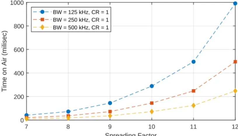
Six orthogonal spreading factor (SF) options are available, from SF7 to SF12, every iteration represents a different compromise between data transmission rates and signal range [38]. Each increment doubles the time on air to transmit the same amount of data, thus the decrease in rate, and increase in the signal perseverance to in band and out band interference noise [39], whilst the decrement of SF will increase the bit rate while sacrificing range. The value of this factor should be decided based on the available bandwidth and signal to noise ratio (SNR). LoRa modulation offers a scalable bandwidth composed by three levels, 125 kHz, 250 kHz and 500 kHz [47], making it capable of performing in both narrowband frequency hopping and wideband direct sequence applications. Additionally, this specification implements a variable error correction scheme that increases robustness by introducing some redundancy [39]. Denoting bit rate as Rb, it can be represented as follows [57], Rb = SF ∗ h 4 4+CR i h 2SF BW i bits/sec, (2.2) where Code Rate = 4 4 + CR , 1 ≤ CR ≤ 4. (2.3)
CR is the so-called coding rate, BW represents the operation bandwidth and SF is an integer ranging from X to Y.
The period of a symbol (Ts) is defined as [57]
Ts = 2SF
BW. (2.4)
Thus, symbol rate (Rs) is given by the reciprocal of the period (Ts) [57]
Rs= 1
Ts
= BW
2SF symbols/sec. (2.5)
Finally, chip rate (Rc) is characterized as [57]
Rc= Rs∗ 2SF =
BW
2SF ∗ 2
SF = BW chips/sec. (2.6)
In essence, the number of chips per second is equal to the bandwidth, 125 kHz of band translate into 125 thousand chips in one second. Increasing the bandwidth will
thereby increase the chip rate and should help the attenuation of the effects caused by heavy multipath fading, which is almost negligible in line-of-sight scenarios [39]. LoRa also inherits CSS modulation resistance to Doppler effect, which causes a small frequency shift of the chip pulse, that in turn introduces a negligible deviation in the time axis of the baseband signal [33]. Messages have a maximum payload length of 243 bytes and a minimum of 59 bytes. Moreover, by employing different spreading factors several messages can transmitted at the same time on the same frequency channel without the risk of communication degradation, notably improving network efficiency and throughput.
Figure 2.8: LoRaWAN stack [74].
The second component, LoRaWAN, is a network layer medium access control (MAC) protocol, developed specifically for low power end devices (EDs), as indicated in Figure 2.8.
Figure 2.9: LoRaWAN network topology [74].
As noted in Subsection2.5.1, LoRaWAN, being a LPWAN protocol, operates in a star topology network, in which gateways are used to hand over the messages between end devices and a central core network server (see Figure 2.9). Nodes are not assigned to a single gateway, instead data transmitted by each node reaches several gateways, which in turn forward the received packages to a network server, most likely cloud based as discussed in Subsection 2.1, using a backhaul solution. Messages only travel one hop from
2 . 5 . N E T WO R K L AY E R S P E C I F I C AT I O N S
a node to the gateway. Measures against duplicate packages, package security checks and routing to specific applications should be implemented at the gateway or network server. LoRaWAN defines three distinct end device classes, each with its own MAC protocol (see Figure 2.10), to accommodate trade-off variations between network downlink
commu-nication latency versus battery life [66]. Class A offers the best battery life and biggest latency. Class B defines a middle ground, whilst class c devices have the lowest latency at the cost of battery life.
Figure 2.10: LoRaWAN end device classes [66].
• Class A - End devices uplink (UL) transmissions are followed by two downlink (DL) receive windows from the server. The first DL frame transmission (Rx1) occurs a short delay after the arrival of the sent package, then followed by the second frame (Rx2). Scheduling is decided by the ED itself based on its needs, similarly to ALOHA protocol. This is the most energy efficient end device class and is ideal for scenarios where DL communication from the server is only needed shortly after a device UL communication. If the server chooses to establish communication with a device at any other given time it has to wait until the next UL transmission. Class A devices are typically, but not exclusively, battery powered sensors.
• Class B - End devices are able to receive additional Rx frames during the DL period, at a specified duration, after the arrival of Rx1 and Rx2 frames defined in class A. The duration is established by a beacon frame sent by the gateway on a regular periodic time slot known as beacon delay. Upon receiving a beacon, end devices open a receive window called ping slot, at the specified interval. Essentially, class B devices allow the gateway to control when they should listen. This kind of devices are usually battery powered actuators.
• Class C - End devices not only open the two receive windows defined in class A, but also a continuous one until the end of a transmission. Hence, these devices can always receive data, except in the time frame of a UL operation. It has the lowest latency and higher receive capacity for data exchange from the server, being ideal for applications that mainly require downlink operations. Class C devices are the most energy demanding, thus should be used for applications that have a high amount of energy, being able to neglect the need to minimize receive windows. These devices are generally main powered actuators.
In summary, all classes support bidirectional communications. Class A allows downlink communication after every uplink operation, class B enables downlink scheduling and finally class C is always available for downlink transmissions, except when a device has to execute an uplink operation. Class A devices only support unicast messages, whereas the remaining afford both unicast and multicast.
Sigfox is an LPWAN cellular like network that offers an end-to-end IoT connectivity solution for low-throughput applications. It uses Binary Phase Sift Keying (BPSK) as an Ultra Narrow Band (UNB) modulation achieving communication with very low noise levels, low power outlay and efficient bandwidth consumption [46] alongside a bit rate of 100 or 600 bps depending on the region [65]. Conversely to LoRaWAN, Sigfox is not an open protocol by which its use is limited to Sigfox proprietary networks, deployed all over the world.
2 . 5 . N E T WO R K L AY E R S P E C I F I C AT I O N S
The UNB fundamental consist in transmitting a signal over a very small bandwidth (less than 1 kHZ), resulting in signals with high power spectral density (PSD) inherently reducing the energy required to trample the noise floor [5]. Furthermore, signals with high PSD have a natural resistance to interference, which proves advantageous in crowded bandwidths. Sigfoxs benefits greatly from these properties since the messages are only 100 Hz wide [65]. In spite of UNB modulation positive effects on the link budget its proprieties are also a source of concern, signals with small bandwidths are particularly susceptible to Doppler effect. Small frequency shifts caused by the variation of the relative distance between a receiver and a source over time can become bigger than the signal bandwidth itself, increasing the probability of message collision as well as hinder its detection/demodulation [5]. To address this issue and increase quality of service, Sigfox implements a random access feature. Each uplink message is sent on a random frequency and then followed by two copies transmitted with a different frequency and time, while base stations search the full unlicensed ISM spectrum (868 to 868.2 MHz in Europe) for UNB signals. This feature also somewhat outlines reliability problems caused by Sigfox lack of message arrival acknowledgment [38]. Downlink messages have to be requested by an ED and can be received upon a twenty second delay after the transmission of the first message, its frequency is equal to the frequency of first frame sent, plus a known delta [65]. Receive windows last a maximum of twenty five seconds. The lack of messages’ synchronization between end devices and base stations before a transmission, coupled with ED very low power consumption while idling, are the main factors accountable for Sigfox devices high energy efficiency, thus ensuring long battery life.
Message payload goes from zero (keep alive messages) to twelve bytes in uplink opera-tions, enough to transfer sensor information, GPS coordinates and even some application data. Meanwhile, downlink messages have a static payload size of 8 bytes. European regulations dictate the amount of time Sigfox can occupy the public spectrum to about 30 seconds of transmission time per hour (duty cycle of 1%), resulting in a average of 140 UL and 4 DL messages per day [65].
The overall network architecture is divided into two main layers, the network equipment and Sigfox support system. The former is composed by all the base stations charged with receiving end device messages and delivering them to the later. Sigfox support system layer, as the name implies, enclosures all the support mechanisms necessary to ensure the deployment, operation and overseeing of the network (see Figure 2.12). Its cloud portion provides back-end servers for message and base station monitoring and management, as well as a database for information storage. The web-interface and API section allows customer to access data they collected trough a web browser interface or own information technology (IT) system. Messages are transfered between the two layers through a backhaul that
Figure 2.12: Sigfox network structure [65].
NB-IoT is a narrow band cellular Internet of things (CIoT) technology, standardized by the third generation partnership project (3GPP) release 13, designed to offer low device power consumption and cost, improved indoor coverage, low delay sensitivity and the ability to handle a multitude of low-throughput devices [25]. Cellular network protocols are already capable of performing M2M communications, but were not designed to have power constrains nor handle small message transmissions [5], NB-IoT tackles this inaptitude allowing the repurposing of already established cellular networking infrastructures for long range IoT applications. Under these terms, converse to LoRa and Sigfox, this specification operates in the licensed frequency spectrum (700 MHz, 800 MHz and 900 MHz) and was laid out in a way that enables it to coexist with LTE and GSM. As a matter of fact, NB-IoT is essentially a stripped version of LTE protocol, it discards characteristics redundant in an IoT context and enhances the remaining [38]. It occupies a frequency bandwidth of 200 KHz, equivalent to one resource block (RB) in a GSM and LTE transmission [38], and offers three modes of operation (Figure 2.13):
• Stand-alone - Refarming of Global System Mobile Communications (GSM) channels. Between each RB of GSM there is an unused 10 KHz interval; remaining on both sides of the spectrum;
• In-band - Utilizing resource blocks of a normal LTE carrier;
• Guard-band - Take avail of an unused resource block within a LTE carriers guard-band.
Whilst performing downlink operations this specification uses QSPK and OFDMA modulations with sub-carriers of 15 KHz. In uplink, it adopts BPSK or QPSK coupled
2 . 5 . N E T WO R K L AY E R S P E C I F I C AT I O N S
Figure 2.13: NB-IoT modes of operation [38].
with SC-FDMA technology, offering the options of a single or multiple sub-carrier waves, 3.75 KHz or 15 KHz and 15 Khz wide, respectively. Transmissions rates are identical, from 160 and 250 k/bits per second, with the exception of uplink transmissions using single sub-carriers that reach a maximum speed of 200 K/bits per second.
Like LTE, NB-IoT uses the ETSI standard EARFCN to display the carrier channel number and frequency band rather then the actual frequency in Hertz, which can be obtained through equations (2.7) and (2.8). EARFCN values can range from zero to 65535.
FDL = FDLlow+ 0.1(NDL− Nof fDL) + 0.0025 ∗ (2MDL+ 1) Hz (2.7)
FU L = FU Llow+ 0.1(NU L− Nof fU L) + 0.0025 ∗ (2MU L) Hz (2.8)
where
FDL/U L = Downlink/uplink frequency band;
FDL/U Llow = Carrier lowest frequency in a given band;
MDL/U L = NB-IoT channel number offset for downlink/uplink;
NDL/U L = EARFCN (LTE band and carrier frequency unique identifier) ;
Nof fDL/U L = Minimum range of NDL/U L for downlink/uplink (lowest defined
EARFCN for the band).
NB-IoT follows a common Internet of things architecture, as depicted in Figure 2.14. NB-IoT terminal comprises the sum of all devices integrated into the system. The base stations refers to pre-existing nodes deployed by telecom operators. Usually these support all three of the aforementioned modes of operation. Core network behaves akin to a bridge, enabling connections between BS and a cloud platform. The cloud platform offers and performs a plectra of services then forwards outputs to the vertical business center whose function is up to the client. Typically this layer contains GUI for viewing of data collected by the system as well as control mechanisms for actuators or any other device embedded into the terminal layer.
LoRaWAN SigFox NB-IoT
Modulation CSS BPSK QPSK
Spectrum Unlicensed ISM bands Unlicensed ISM bands Licensed LTE
frequency bands Frequency Europe 868 MHz 868 MHz Licensed LTE frequency bands Frequency North America 915 MHz 915 MHz Licensed LTE frequency bands Frequency Asia 433 MHz 433 MHz Licensed LTE frequency bands Bandwidth 125 kHz 250 kHz 500 kHz 100 Hz 200 kHz Maximum message payload
59-230 bytes 12 bytes (UL)
8 bytes (DL) 1600 bytes Adaptive data rate Yes (SF dependent) No No Range 5 km (urban) 20 km (rural) 10 km (urban) 40 km (rural) 1 km (urban) 10 km (rural) Authentication and encryption
AES 128b Not supported LTE encryption
Private network option Yes No No Standardization LoRa-Alliance Currently in the works with ETSI 3GPP
![Figure 2.2: IoT three layers architecture [76].](https://thumb-eu.123doks.com/thumbv2/123dok_br/15497268.1043916/34.892.145.749.158.463/figure-iot-three-layers-architecture.webp)
![Figure 2.6: M2M protocols usage versus standardization (adapted from [42]).](https://thumb-eu.123doks.com/thumbv2/123dok_br/15497268.1043916/40.892.254.627.592.873/figure-m-m-protocols-usage-versus-standardization-adapted.webp)
![Figure 2.7: Data rate vs range of radio communication technologies [38].](https://thumb-eu.123doks.com/thumbv2/123dok_br/15497268.1043916/42.892.228.658.317.578/figure-data-rate-vs-range-radio-communication-technologies.webp)
![Figure 2.10: LoRaWAN end device classes [66].](https://thumb-eu.123doks.com/thumbv2/123dok_br/15497268.1043916/45.892.291.601.338.670/figure-lorawan-end-device-classes.webp)
![Figure 2.14: NB-IoT network structure [12].](https://thumb-eu.123doks.com/thumbv2/123dok_br/15497268.1043916/51.892.275.622.159.419/figure-nb-iot-network-structure.webp)
![Figure 2.21: DIAT architecture BDIP mode [52].](https://thumb-eu.123doks.com/thumbv2/123dok_br/15497268.1043916/64.892.273.637.156.415/figure-diat-architecture-bdip-mode.webp)
![Figure 2.24: Semantic gateway as service [72].](https://thumb-eu.123doks.com/thumbv2/123dok_br/15497268.1043916/65.892.219.663.805.1041/figure-semantic-gateway-as-service.webp)
![Figure 3.5: Protocol stack of LoRaWAN network components [35].](https://thumb-eu.123doks.com/thumbv2/123dok_br/15497268.1043916/75.892.141.769.460.750/figure-protocol-stack-lorawan-network-components.webp)
