https://periodicos.utfpr.edu.br/rbfta
Low cost MFC control unit using
microcontroller
ABSTRACT
Paulo R. Espindola
[email protected] Universidade Federal do Mato Grosso do Sul (UFMS), Campo Grande, MS, Brasil.
Mariana L. Aquino
Universidade Federal do Mato Grosso do Sul (UFMS), Campo Grande, MS, Brasil.
Cícero R. Cena [email protected]
Universidade Federal do Mato Grosso do Sul (UFMS), Campo Grande, MS, Brasil.
Diego C.B. Alves [email protected]
Universidade Federal do Mato Grosso do Sul (UFMS), Campo Grande, MS, Brasil.
Diogo D. Reis [email protected]
Universidade Federal do Mato Grosso do Sul (UFMS), Campo Grande, MS, Brasil.
Além-Mar B. Goncalves
[email protected] Universidade Federal do Mato Grosso do Sul (UFMS), Campo Grande, MS, Brasil.
.
In this paper we present a compact and low cost solution to set up and to monitor an electronic Mass Flow Controller (MFC) using an Arduino microcontroller. The control unit produced is presented in details with a detailed configuration for connect the controller to the MFC. The control unit is also capable to work with two MFCs simultaneously at manual and remote regime. The source code is quite simple and allows the user easily modify parameters as type of gas and flux capacity of the controllers. Although the low resolution of ADC (Analog-to-Digital Converter) (10 bits) and DAC (Digital-to-Analog Converter) (using PWM, 8 bits), the flux can be adjusted in steps of 1.5 % of the total flux, which is very satisfactory for practical purposes. Finally, the operation tests were taken by using Argon gas, and great accordance between the set point flow and the MFC measured flow was found.
INTRODUCTION
In the past few decades, the processing of nanomaterials has attracted the interest of many research groups. This can be attributed to their great properties, providing new perspectives for technological applications and phenomenological studies. In this context, a large variety of synthesis routes have been extensively exploited, among them stands out the chemical vapor deposition (CVD) (JONES and HITCHMAN, 2008).
The CVD can be considered as one of the most common large scale production process. The main role of this technique is to generate chemical vapors precursors and then deliver it through a hot zone (reactor) of a furnace, where the chemicals react producing a new material. In general, the delivery of the reactants depends on the source temperature, carrier gas flow rate and pressure over the substrate surface. This technique has been successfully employed to produce graphene (ZHANG et al., 2013), bidimensional materials as BN, MoS2, WS2, etc. (YU et al., 2013), composite ceramics (CHOY, 2003; HACKL et al., 2013), and others systems (JONES and HITCHMAN, 2008).
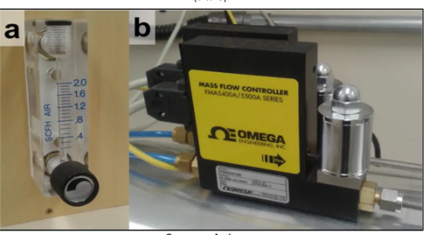
Usually, the demand of precise gas flow control in a CVD system, or even in others techniques (physical vapor deposition, sputtering, etc.) is performed by a rotameter or an electronic mass flow controller (MFC). The working principle of a rotameter (Figure 1a) is based in a mechanical process, in which the gas flow is controlled by a needle valve and the flux measurement is based on the height reached by a metallic sphere inside a conical tube, however this method cannot be automated by the low cost setup presented in this paper.
In other hand, the MFC (Figure 1b) controls the gas flux by an electrovalve which uses the temperature variation between two points inside a capillary tube. Thus, the MFC needs an electronic control unit to handle all input and output information and correctly adjust the gas flux. Usually, most of the commercial control units are very expensive, besides that some of them do not even have a computer interface to automate the system.
Figure 1- Gas flow rate controls (a) rotameter, and (b) electronic mass flow controller (MFC)
In this paper, we present a detailed procedure to build a low cost electronic control unit capable to operate up to two MFCs simultaneously by using a microcontroller (Arduino). Arduino board has been used as a low cost microcontroller to implement automation control at laboratorys ( ANGALAESWARI et al, 2016; GALI, 2017; GRINIAS et al., 2016) In addition to manual control, our homemade control unit can be operated remotely by a computer through the Arduino communication port (for example, using LabView) (SCHWARTZ and MANICKUM, 2015).
This enables, by using a proper software, integrate the gas flow control with other systems, such as, temperature control in a CVD process, a source-meter in case of a gas sensor measurements, etc. In the presented case, it is employed to control gas flow inside a horizontal quartz tube furnace, used to grow two-dimensional materials.
EQUIPMENT DESCRIPTION
The control unit was designed using an Arduino Nano (ARDUINO NANO BOARD, 2016) to control, monitor and display the gas flow through a MFCs, as well as embedded power source that is also used to feed the MFCs. We decide to use Arduino Nano as microcontroller for three reasons: its small dimensions, low cost (less than $10.00), and it can connected direct to the 12V power source (same that is used with MFC’s).
As a standalone control unit, potentiometers are used to adjust the desired setpoint and a push button confirms the setpoint, sending the proper information for the chosen MFC (inset Figure 2).
The value seted by the potentiometer is read directly by analog port of the Arduino. In series with the pushbutton we put a resistor to prevent short-circuit of the Arduino.The setpoint and the real amount of gas flowing through the MFC can be monitored by a LCD display.
The connection between the control unit and both MFCs (Omega FMA5400 series) is made through a 15 pin conector (DB15). Through this connection the information is send from the Arduino to the MFC as well as the data sent by the MFC is read by the Arduino.
The function of each pin is presented on Table 1. The pin number 2 of each MFC is connected to analog pins A2 and A3, and they are responsible to read the flow measured by MFC1 and MFC2 respectively. The pin number 8 is connected to digital pins D10 and D6, they send the setpoint flow.
The 5 V reference pin number 11 is connected to digital pin D9. The pins 3 and 12 of each MFC are connected to a safe on/off switch. On the off position, this switch put the controller on the “listen only” mode, preventing undesired change on the gas flux.
Figure 2 shows a diagram of the circuit mounted using the free online tool 123d Circuits (123d.circuits.io) and a picture of our finished control unit (inset).
For remote control the on/off switch should be on (it is not remotely controlled), the setpoint adjust and flow read can be performed on remote way.
Table 1- FMA 5400 mass flow controller 15-pin “D” Connector configuration
PIN NUMBER FUNCTION
1 0 to 5 V Flow Signal Common
2 0 to 5 V Flow Signal Output
3 Common
4 Open (Purge)
5 Common, Power Supply
6 (unassigned)
7 +12 V Power Suplly
8 Remote Setpont Input
9 4 to 20 mA (-) Flow Signal Return
10 Remote Setpoint Common
11 +5 V Reference Output for Remote Setpoint
12 Valve Off Control
13 Auxiliary +12V
14 4 to 20 mA (+) Flow Signal Output
15 Chassis Ground
Source: Autors.
For manual operation the setpoint is adjusted by the potentiometer and, after confirm it pushing the button the value is send to MFC to control the electrovalve.
Figure 2- Scheme of circuit to control the MFCs. Inset, a picture of finished control unit box.
Source: Autors.
In order to keep the flow constant in the setpoint required the MFC measures the gas flow. The signal (0 to 5 V) send by MFC is read in the analog pin and converted to the value in SCCM (Standard Cubic Centimeters per Minute).
The source code (Arduino code) used in our control unit is shown at Figure 3 below:
Figure 3- Souce code for Arduino.
Source: Autors.
Basically, the MFC works with a setpoint signal from 0 to 5 V, where 0 V means closed valve, and 5 V means the valve totally open. In our source code is
possible to insert the coefficients that permit the conversion of the 0 to 5 V signal in the real flow in SCCM by means of the equation: GAS = GCF * TFR, where the coefficients are related to the gas type that is used (GCF) and the total flow rate (TFR) of the equipment.
Since the MFC is calibrated using nitrogen (GCF = 1.00), in general, a conversion factor needs to be used in order to use other gases (like Argon, GCF = 1.4573, in our case).
RESULTS AND DISCUSSION
The Arduino has an ADC resolution of 10 bits to analog input. It does not have an analog output, but an analog signal can be simulated by the PWM output with a resolution of 8 bits. It means that the potentiometer signal read by Arduino is divided in 1023 steps but the Arduino is capable to send to MFCthe same range divided in 255 steps.
To correct it and to show the setpoint with the same value sent to the MFC we rescale the 10 bit resolution to a 8 bit resotution values. Although PWM is not a real analog signal, the fact is that the high frequency pulses do not affect the MFC response, behaving as the same way with a real analog input. An 8 bits resolution means a resolution of about 0.4% of the total flow rate, which, for practical purposes, is a good resolution.
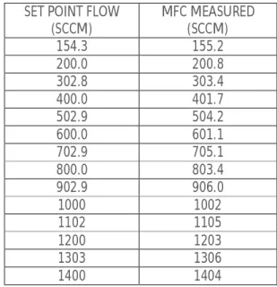
Table 2- Values of setpoint flow and MFC flow using a 1457 sccm total flow rate with Argon
SET POINT FLOW (SCCM) MFC MEASURED (SCCM) 154.3 155.2 200.0 200.8 302.8 303.4 400.0 401.7 502.9 504.2 600.0 601.1 702.9 705.1 800.0 803.4 902.9 906.0 1000 1002 1102 1105 1200 1203 1303 1306 1400 1404 Source: Autors.
We show on Table 2 the results of setpoint and flow measured by the MFC. As can be observed the values are practically the same. The few differences are related to difference in resolution of ADC and PWM, because with we continue reading the MFC flux with total resolution of the ADC.
CONCLUSIONS
In this work we showed a low cost control unit to control two MFCs using an Arduino microcontroller. The control unit was successfully employed to their purposes. The control was precise and versatile, with 0.4% resolution for setpoint and 0.1% for read the flow, and the values of setpoint and read flow could be displayed in A LCD. The USB port of Arduino makes the unity able to be controlled by a computer.
Unidade de controle de baixo custo de um
MFC utilizando um microcontrolador
RESUMO
Neste trabalho, apresentamos uma solução compacta e de baixo custo para controle e monitoramento de um Controlador de Fluxo de Massa (MFC) eletrônico utilizando um microcontrolador Arduino. A unidade de controle produzida é apresentada em detalhes, juntamente com as conecções entre o microcontrolador e o MFC. A unidade de controle montada é capaz de trabalhar com dois MFCs simultaneamente por via manual ou remota. A fonte código é simples e permite ao usuário modificar os parametros utilizados, tais como tipo de gas e capacidade de fluxo dos controladores. Embora possua baixa resolução de ADC (10 bits) e DAC (utilizando PWM, 8 bits), o fluxo pode ser ajustado em passos de 0.4% do fluxo total, o qual é satisfatório para aplicações práticas. Finalmente, testes de operação foram realizados utilizando gás Argônio, e boa concordância entre os parâmetros de entrada e os medidos no MFC foram obtidos.
PALAVRAS CHAVE: MFC; Controlador de baixo custo; Microcontrolador; Arduino. Fluxo de gas.
Unidad de control MFC de bajo coste con
microcontrolador
RESUMEN
En este trabajo, presentamos una solución económica y compacta para el control y la supervisión de un controlador de flujo másico (MFC) y electrónico con un microcontrolador Arduino. La unidad de control producida se muestra en detalle junto con las conexiones entre el microcontrolador y el MFC. La unidad de control montada es capaz de trabajar con dos MFC simultáneamente por manual o de forma remota. El código fuente es simple y permite al usuario modificar los parámetros utilizados, como el tipo de gas y el control de la capacidad de flujo. Aunque tiene baja resolución ADC (10 bits) y DAC (mediante PWM, 8 bits), el flujo se puede ajustar en pasos de 0,4% del total de flujo, que es bastante satisfactorio para aplicaciones prácticas. Finalmente, las pruebas de funcionamiento se realizaron con gas argón, y se obtuvieron buena correlación entre los parámetros de entrada y el MFC medido.
PALABRAS CLAVE:MFC; Controlador de bajo costo; Microcontrolador; Arduino; Flujo de
ACKNOWLEDGEMENTS
The authors would like to acknowledge the Brazilian financial support agency CNPq (Project number 475807/2013-8).
REFERENCES
ANGALAESWARI, S., et al. Speed Control of Permanent Magnet ( PM ) DC Motor Using Arduino And LabVIEW, Computational Intelligence and Computing Research (ICCIC): IEEE International Conference, Chennai, India, 2016.
ARDUINO NANO BOARD. https://www.arduino.cc/en/Main/ArduinoBoardNano. Acesso em agosto 2016.
CHOY, K. L. Chemical vapor deposition of coatings, Progress in Materials Science, v. 48, p. 57-170, 2003.
GALI, H. An Open-Source Automated Peptide Synthesizer Based on Arduino and Python, SLAS TECHNOLOGY: Translating Life Sciences Innovation, v. 22, n 5, p. 493-499, 2017.
GRINIAS, J. P., et al. An inexpensive, open-source USB Arduino data acquisition device for chemical instrumentation, Journal of Chemical Education, v. 93, n. 7, p. 1316–1319, 2016.
HACKL, G., et al. Coating of carbon short fibers with thin ceramic layers by chemical vapor deposition, Thin Solid Films. v. 513, n.1-2, p. 217-222, 2006. JONES, A.C.; HITCHMAN, M.L. Chemical Vapour Deposition, Cambridge : Precursors, Processes and Applications, Royal Society of Chemistry, 2009.
SCHWARTZ, M., MANICKUM, O. Programming Arduino with Labview : build interactive and fun learning projects with, Birmingham: Packt Publishing, 2015.
ZHANG, Y., et al. Review of chemical vapor deposition of graphene and related applications, Accounts of Chemical Research, v. 46, n. 10, p. 2329-2339, 2013.
YU, J., et al. Synthesis of high quality two-dimensional materials via chemical vapor deposition, Chemical Science, v. 6, p. 6705-6716, 2015.
Recebido: 20 de fevereiro de 2017. Aprovado: 25 de outubro de 2017. DOI:
Como citar:
ESPINDOLA, P.R. et al, Low cost MFC control unit using microcontoller, Revista Brasileira de Física
Tecnológica Aplicada, Ponta Grossa, v. 4, n.2, p. 1-11, dezembro de. 2017. [email protected]
Contato: Paulo R. Espindola:
Direito autoral: Este artigo está licenciado sob os termos da Licença Creative Commons-Atribuição 4.0 Internacional.