ABSTRACT: In this paper, a constellation of four low earth orbit nanosatellites for disaster monitoring is presented; their small size, low cost, and short time development give them the opportunity to be widely selected. The space segment is based on existing subsystems that are assembled on the bottom part of a developed structure and present acceptable performance for the mission. The payload is a multispectral camera which fulills the mission’s requirements (remote sensing). The ground segment is based on an existing modular ground station, used for the ALSAT-1 DMC, which will be adapted to it with the speciications of the mission.
KEYWORDS: Nanosatellite, Constellation, Earth observation, LEO orbit.
Disaster Monitoring Constellation
Using Nanosatellites
Mohamed Kameche1, Haider Benzeniar1, Ayhane Bey Benbouzid1, Redha Amri1, Nadir Bouanani1
INTRODUCTION
African and Asian developing countries need support to face natural disasters such as loods, forest ires, desertiication, and locust monitoring. he problems of desertiication and locust are especially related to African countries, which are not able to handle them.
his paper describes a mission idea, to develop a low cost disaster monitoring constellation using four Nanosatellites, which allows diferent Asian and African developing countries to access satellite images, in order to face diferent natural disasters. he designed system consists on a space segment which is composed by two main parts. he bottom part of the structure – also called platform – has the same dimensions used for the U6 Cubesat platform structure to hold the existing different functions – Attitude and Orbit Control Systems (AOCS), Radio Frequency (RF), power, thermal, propulsion, On-Board Data Handling (OBDH), etc. he upper part of the structure – also called payload structure – is used in order to hold the camera (optic and electronic subsystems). he ground segment is based on an existing modular ground station, used for the ALSAT-1 DMC, which will be adapted to it with the mission requirements.
he paper is subdivided into six sections. In the irst section, the Mission Objectives are presented, followed by the Concept of Operations, and then the mission Key Performance are highlighted. he Space Segment, Orbit and Constellation are described further on. he last section of this work is dedicated to the Implementation Plan.
1.Centre de Développement des Satellites – Bir Eldjir/Oran – Algeria
Author for correspondence: Mohamed Kameche | Centre de Développement des Satellites Agence Spatiale Algérienne | BP 4065, Ibn Rochd USTO | 31130 |
Oran/Algeria | Email: [email protected]
MISSION OBJECTIVES
h e main objective is to launch the i rst low cost disaster monitoring constellation, which allows dif erent Asian and African developing countries to access the satellite images, in order to face dif erent natural disasters.
• Floods: analysis and assessment of damage caused by l oods, ability to restore decisions of the authorities with the necessary key information for emergency measures to be undertaken;
• Locust biotopes monitoring: analysis of ecological conditions in the regions of desert locust breeding; • Forest i res: characterization of forest, prevention against
forest i res, and aid for decision taking by the authorities; • Desertii cation: tracing of dif erent maps of desertii cation
sensitivity for many African countries.
h e other main objective of this mission is to encourage the African developing countries to acquire the space technology, to develop low cost constellation for their economic development and to obtain a multidisciplinary team which, by the end of the project, shall be able to design, to integrate and to operate a full nanosatellite mission.
In absence of disaster, the constellation is dedicated for educative and scientii c purposes.
CONCEPT OF OPERATIONS
The mission consists of a constellation of four Nanosatellites, and a ground segment for commands, telemetry and monitoring and for image processing. The launcher, to be selected for the constellation, is Polar Satellite Launch Vehicle (PSLV), which presents the advantage of its low cost, regarding other launchers.
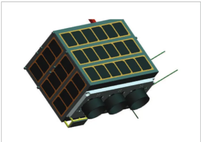
h e space segment is a nanosatellite, consisting of two main parts: platform and payload, with a total mass below 12 Kg (around 6 kg for each part). h e developed structure is designed to have the same internal dimensions to support modules already used on ISIS 6U platform (CubeSat Kit, 2011). h e payload is a multispectral pushbroom imager, suitable for wide range of missions in Low Earth Orbit (LEO). It is encapsulated in a compact unit and provides three multispectral channels, with an ef ective sensor length of 2098 pixels per channel.
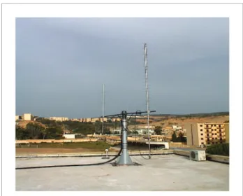
To support the four nanosatellites of the constellation, an exis ting modular ground station used for the ALSAT-1 DMC will be adapted to i t the requirement of the mission (Amri, 2002). h e existing ground station supports the communication in VHF/UHF/S-band (Fig. 1). It is implemented in the “Centre of space techniques building”, located in Arzew, west of Algeria. It includes Yagi-Uda antennas and radio for the bidirectional UHF communications and for receiving the VHF beacon (Fig. 2) and a 3.7 m parabolic dish and radio, for receiving and transmitting the S-band signal (Fig. 3). The ground station sot ware will be modii ed and adapted to meet the mission’s requirements.
Regarding the operational concept, three operation phases are summarized below:
BEFORE NOMINAL OPERATION
h e Launch and Early Operations Phase (LEOP) starts at er the satellite separation from the launcher. h is phase includes
TLE
GPS TIME
TRACKING TM/TC ARCHIVE IMAGE PROCESSING
RELAY SWITCH UHF/VHF S/BAND
Figure 1. Ground station architecture diagram.
the antenna’s deployment, the initial satellite acquisition (beacon signal), the validation of the satellite-ground station link, the switching of the equipments on, the acquisition, and the transmission of the i rst image to check that the satellite is not damaged during launch. At er the i rst image, a phase of orbit correction will be performed to position each satellite in its mission orbit. h e duration of LEOP phase depends strongly on the injection conditions (dispersions, initial injection velocity of each nanosatellite, etc). h e period of corrections depends on the accuracy of injection by the launcher. Once the satellite is placed on its mission orbit, a commissioning phase starts. During this phase, the performances of the satellite will be tested and validated. h e results will be used to correct and calibrate the on-ground satellite models.
NOMINAL OPERATIONS
During nominal operation phase, the satellite will be fully operational and shall perform the Earth observation mission in accordance with the defined timeline. This phase starts from the end of the commissioning phase up to 24 months after launch.
CONTINGENCY OPERATIONS
In order to avoid surprises during different phases (in particular the LEOP phase) and to prepare the solutions in advance, to predict possible failure scenarios and recovery plans will be elaborated.
KEY PERFORMANCE PARAMETERS
For each nanosatellite, the camera used gives a 146-kilometer i eld of view at a 62-meter spatial resolution in three spectral bands, the Red, the Green and the Near Infra-Red. h is i eld of view allows the constellation to cover the whole Earth within 72 hours and to communicate with the main ground station, located in Algeria or other (so-called) auxiliary ground stations situated in other developing countries. h e band spectrums selected for this mission are the Red: [0.22-0.69] mm, Green: [0.52-0.60] mm, and Near Infra-Red (NIR): [0.77-0.90] mm.
h e nanosatellite is three axis stabilized when imaging and evolves in a Barbeque Mode (BBQ) mode out of imaging time. h e Attitude Determination and Control Subsystem give attitude pitch/roll/yaw stability during imaging of less than 0.2 deg. h e imaging system allows windowing, and it is supported by a total storage capacity of 2 Gbytes. h e mission is designed to record the maximum of 16 elementary images of 2098 x 2098 pixels per day, which could be downloaded to a ground station at a 1 Mbps data rate, within four visibilities per day, with a total duration of about 32 min.
In order to assure the circularization of the constellation satellites, the station acquisition (which allows the satellites to equally separate from each other, so the daily global coverage is respected), and the station keeping of the four satellites, each nanosatellite of the constellation is equipped with a propulsion system of 50mN thrust and a 0.9-liter-capacity tank. The estimated preliminary delta V total is about 25 m/s and it can reach up to 30 m/s.
h e mission lifetime for each nanosatellite is 18 months and it can reach 24 months or more, by introducing added protections against radiations (shielding on the sensitive equipments).
SPACE SEGMENT DESCRIPTION
attitude control system, and will be oriented based on the Earth’s magnetic i eld. h e structure will be designed to meet its mission objective and to meet the specii cations of the interface system that will be used for launching vehicle integration (Fig. 4).
h e Nano-satellite specii cations state the maximum mass allocation at 15 Kg, since it is the preliminary design, and the mass budget is based on the primary design, it will be updated in the following phases. h e overall mass of the satellite is about 11.5 Kg, which means a margin of about 23.34%.
In the choice of the components, the tolerance to radiation had to be considered towards the harsh LEO environment. h e anti-fuse rad-hard Field-Programmable Gate Array (FPGA) for Payload data handling, the anti-latch-up function in the command data handling system, and the experience learning from similar Cubesat based mission flying with analogue chip, reveal over estimated ef ective mission lifespan as Libertad-1 and Deli -C3. Also, the interior arrangement of sub-systems boards had to be done according to former Cubesat based missions, by setting the On-Board Computer (OBC) between the other boards. h e Commercial Of -h e-Shelf (COTS) selected have tolerance up to 500krad of radiation and temperature tolerance in the range of - 40 to 85°C.
PAYLOAD
h e objective of the mission is to take, process, store, and transfer, during one visibility, up to three or four elementary images of 2098 x 2098 pixels (15.75 Mbytes). To achieve this, we have selected a line scan camera system, designed to provide medium resolution of 62m, high dynamic range and low noise imagery. h e image sensor selected is KODAK KLI-2113 with an imager size of 29.37 mm x 0.24 mm, which of ers high sensitivity, high data rate and low noise. For each sensor, only one line among three is derived to obtain one active Charged-Coupled Device (CCD) line for each multispectral band.
To meet the mission requirements (low cost and time development), the sensor element will be requested without the RGB (red-green-blue) organic dye i lters. A specii c i lter is procured from BARR to achieve the required spectral bands. h e lens is a Schneider Apo-Componon. It’s a l ight proven lens (l own onboard Tsinghua-1 and Alsat-1). h is commercial lens has been subject to a set of tests, prior to use. h e camera board consists in a three video chain, composed by each of a pre-amplii er for CCD signal and a correlated double sampling, and a 10 bit A/D converter function, represented
PROPULSION
COLD GAZ
PROPULSION CONTROLER
ACDS
RW X
EPS POWER
SAS X MTB X
SAS Y
SAS Z RW Y
RW Z
TRI-AXIS Angular rate TRI-AXIS Acceleration
sensor TRI-AXIS Magnetic sensor
ACDS MODULE
MTB Y
MTB Z
DATA BUS I2C
POWER
COMMUNICATION
RX 9K6bps
TRANSCEIVER UHF
Beacon Transmitter
OBC
MSP430
Mass storage
Time Synchronisation
GPS TX 9K6bps
PAYLOAD
CCD PAYLOAD DATA
HANDLING
CCSDS
S-BAND TX 1Mbps
BATTERY
SOLAR PANEL
in Analog device 9840A chip. Meanwhile, a high density FPGA is used to interface, via the used bus, between the video chain, the mass memory hosted by the on-board data handling FM430 and the TX sub system. A dedicated Actel FPGA RT54SX is used to packetize the mission data in he Consultative Committee for Space Data Systems (CCSDS) format before transmission.
ATTITUDE CONTROL SYSTEM
he main goal of the attitude determination and control system (ADCS) is to guarantee an accurate Earth pointing when imaging. his can be achieved using sensors for acquiring spacecrat attitude and position, and ater performing on-board calculation, or receiving ground commands the spacecrat makes, using actuators to achieve the desired attitude or trajectories. Once the spacecrat achieves a certain desired attitude or orbit, the role of the ADCS is not over, because of the continuous disturbing forces acting on the spacecrat: aerodynamic drag, solar radiation pressure, gravity gradient torques and genetic ield torques.
he proposed ADCS is based on the ADACS IMI200 integrated system from Maryland Aerospace, Inc, that uses three-axis active controls with three reaction wheels and three magnetorquers, providing a 0.02Nms momentum and 5mNm as maximum torque. In addition to that, three sun sensors, triaxial gyroscope, triaxial accelerometer, and triaxial magnetometer are also used to enhance the attitude determination, for accuracy of about 0.2°.
he miniaturized sun sensors are provided from SFL/Sinclair interplanetary Company, and the triaxial inertial sensor with analog magnetometer is from ANALOG DEVICES, Inc. A ixed nadir pointing is set as nominal pointing, for both imaging mission and in eclipse, since the payload is a multispectral camera. he ADCS works with three modes, the detumbling mode – applied ater launch separation using magnetorquers, the imaging mode – with nadir pointing, and the BBQ mode – for thermal equilibrium. In this mode, the satellite is spinning around the yaw axis, which is pointing towards Earth. he imaging and the BBQ modes are achieved by the reaction wheels and the magnetorquers for momentum dumping. However, when proceeding to orbital maneuver, the satellite can slew to some degrees to perform the required maneuver.
he GPS receiver selected is the SGR-05U from SSTL, used for an accurate timing and synchronization.
ELECTRICAL AND POWER SYSTEMS
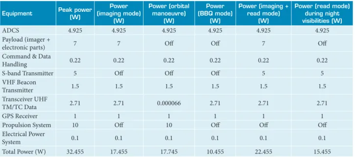
The preliminary satellite power budget estimation in Table 1 shows that the estimated required average power for the imaging and reading mode simultaneously, or only reading mode during night visibilities, are respectively 22 and 15 W, provided by 58 GaAs junctions, placed on the four lateral sides of the structure, and a Lithium Polymer battery (CS-SBAT2-30) with a capacity of 30 W.h and a depth of discharge of 20%. In order to improve the total power provided by solar arrays and the thermal protection of the satellite, the solar arrays will be
Table 1. Nanosatellite power budget estimation.
Equipment Peak power
(W)
Power (imaging mode)
(W)
Power (orbital manoeuvre)
(W)
Power (BBQ mode)
(W)
Power (imaging + read mode)
(W)
Power (read mode) during night visibilities (W)
ADCS 4.925 4.925 4.925 4.925 4.925 4.925
Payload (imager +
electronic parts) 7 7 Of Of 7 Of
Command & Data
Handling 0.22 0.22 0.22 0.22 0.22 0.22
S-band Transmitter 5 Of Of Of 5 5
VHF Beacon
Transmitter 1.5 1.5 1.5 1.5 1.5 1.5
Transceiver UHF
TM/TC Data 2.71 2.71 0.000066 2.71 2.71 2.71
GPS Receiver 1 1 1 1 1 1
Propulsion System 10 Of 10 Of Of Of
Electrical Power
System 0.1 0.1 0.1 0.1 0.1 0.1
speciied in accordance with the exact dimensions of each lateral panel. he battery is required for the mission because the solar cells alone cannot produce enough power when peak power is needed, and it provides power to subsystems that cannot be turned of while the satellite is in eclipse. he power and the electrical subsystems have to accommodate a variety of power needs, as required by the mission timeline. If the satellite is in sunlight and it takes and transmit images to the ground station, the payload and both transmitters (UHF and S-band transmitter) will all need full power to operate. In these conditions, the satellite acquires supplementary power from the battery.
Regarding the calculated peak power (all equipments On) shown in Table 1, it is recommended that no mission (neither imaging nor data reading) will be performed the day of orbital maneuvers, because 10 W is required for the heater
and the pipe heater, to evaporate the liquid butane before injection through the thruster.
COMMUNICATIONS
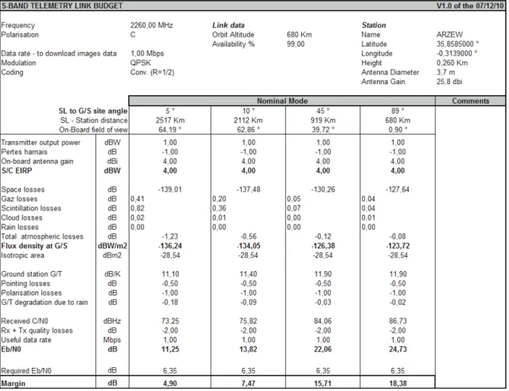
The communication to and from the satellite (control, command, and monitoring) is achieved using a commercial UHF transceiver (NanoCom U480), operating in the amateur radio band. The images data will be transmitted by using an S-band transmitter, operating in the commercial band (2.2-2.29 GHz), with a data rate of 1Mbps and an output power of 1 W. Also, a dedicated transmitter operating in VHF band will be used to send a beacon signal containing satellite health to aid in satellite identification, tracking and monitoring, particularly in the days following launch. Monopole and patch antennas are used for uplink and downlink communications. The uplink and the downlink
Figure 5. Outside satellite coni guration.
radiation and heat l uxes. h is insulation will consist of a layer of Kapton outside the panels, which will also act as an adhesive for the solar panels, and a Multi-Layer Insulation (MLI) inside the structure. Since solar panels will be covering most of the panels, the layer will be acting as an additional insulation. Additional thermal covering will be used around the most thermally sensitive components.
PROPULSION
A butane cold gas propulsion system, utilizing 460 g of propellants to meet the mission’s requirements (ΔV of about 25 m/s up to 30 m/s), will be developed. One tank, with capacity for 0.9 L, will be used for the storage of butane at maximum pressure of 4 bars (Fig. 6). h e tank will be connected to the thrusters, using pipe heater to evaporate the liquid butane before injection through the thruster (Gibbon et al, 2001). h e propulsion system delivers approximately 50 mN thrust.
budgets show very good margins. Table 2 illustrates the S-band Telemetry link budget.
COMPUTER
h e OBC used in the design consists on a single board computer l ight module FM430, designed by Pumpkin, for low cost and low power consumption embedded applications, built around a Texas Instrument 16-bit TI MSP 430 microcontroller, made for harsh environment. h is choice of ers an operational reliability (Libertad-1, Deli -C3). h e l ight Module computer is charged to monitor satellite and payload housekeeping parameters, and manage bidirectional communications with the mission’s ground station, handling data storage as well as retrieving satellite control. h e OBC is the master of the I2C-bus on the satellite, and the other sub-systems are slaves.
SOFTWARE
Salvo Pro RTOS is used to handle all sot ware tasks. Highly coni gurable Pumpkin product of low cost , it can run multiple prioritized tasks and work with a cooperative scheduler. Ideally suitable for MSP430’s 2K RAM, it allows application to sleep at all times, waking only for activity when specii ed events occur. Well documented, it can be developed under Non-intrusive environment and be easily debuged. h e mission specii cations will be developed under Salvo Pro RTOS environment.
STRUCTURE
The proposed structure of the Nanosatellite must hold all the components and i t the specii cations of launch vehicles. h e structure is made of Aluminum and based on two main parts, the platform structure which has the same dimensions of an U6 Cubesat platform to hold the components, and the payload structure for the camera. Four lateral panels are attached to the structure, to support the solar cells. h e camera is placed on the bottom panel in order to point towards Earth (Fig. 5). h e satellite envelope is 340 x 360 x 280 mm3, and the satellite total mass will be less than
12 kg. h e POD-types separation systems cannot be used because of the satellite envelope. For our mission, the AxelShooter separation system is selected, which ensures protrusions such as antennas and camera, and allows the visual inspection and operation check at er the attachment (Axelspace, 2011).
THERMAL
A passive thermal protection system consisting of proper insulation will be used to provide proper protection from
Upper part of structure Bottom part
of structure
⎧ ⎨
⎩
Nanosat 1
Nanosat 4 99.3º
86.9º
Nanosat 3
Nanosat 2 86.9º
86.9º
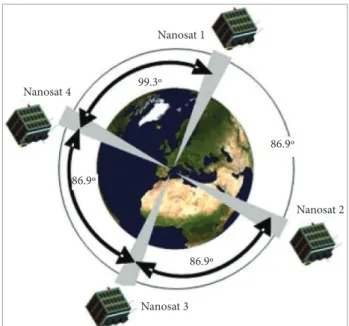
Figure 7. Nanosatellite constellation phasing.
ORBIT AND CONSTELLATION
DESCRIPTION
Since many Nanosatellites are typically launched as a secondary payload, its precise orbital trajectory is dictated by the requirements of the primary mission. Based on previous Cubesat launch trends, a sun-synchronous reference orbit has been chosen with an inclination of 98.08 degrees, an altitude of 670 km over the Equator, and a period of 98.25 mn. The local solar time used in the design is 10h +/- 30 mn, and it will be adjusted when the launch opportunity is defined. This orbit allows the obtaining of an image swath of 146 km, which allows the four satellites of the constellation to cover the whole earth within 96 hours.
For a reference orbit with a repetitivity of (14 + 19/29), the position of the four satellites in the constellation will be: Nanosat 1 is dei ned as the reference position; Nanosat 2 is located at about 86.9 degrees from Nanosat 1; Nanosat 3 is located at about 86.9 degrees from Nanosat 2; and i nally, Nanosat 4 is phased 86.9 degrees from Nanosat 3or 99.3 degrees from Nanosat 1, in opposite direction (Fig. 7).
It also allows the ground station to communicate with the satellites four times per day, with an average duration of 8 min per visibility. h e minimum elevation considered for VHF/UHF/S-Band communications is 5 deg.
This reference orbit is a design guide built from historical averages, and additional worst-case figures must be considered whenever possible throughout the mission’s design process. In order to have different earth coverage by each satellite, and to avoid simultaneous visibility of two nanosatellites or more from the main ground station, the reference mission orbit of each satellite, and especially the argument of latitude, will be carefully defined. The description of the position of the nanosatellites constellation is done according to Fig. 7.
IMPLEMENTATION AND CONCLUSION
h e Satellite Development Centre is the technical entity, working with the Algerian Space Agency on the conception, realization and operations of dif erent satellite missions (Earth observation, communication). To date, two Earth observation microsatellites have been successfully launched (ALSAT-1 and ALSAT-2A) and a third satellite ALSAT-2B is planned to be launched within the two following years. h e two i rst satellites have been successfully accomplished with the cooperation of the SSTL for ALSAT-1 and the EADS-Astrium for ALSAT-2A.
For this mission, the conception, the accomplishing, the integration, and the tests of at least one nanosatellite of the constellation, will be performed in the Centre of Space Techniques CDS facilities. h e CDS is a new centre located in Oran city (Algeria). It has been inaugurated in February 2012. It contains a clean room, vacuum, acoustics, vibration and RF facilities to perform environmental tests.
REFERENCES
Amri, R., 2002, “ALSAT-1 documentation”, ALSAT-1 Project Documentation.
Axelspace, 2011, “Nano-Satellite Separation Mechanism AxelShooter”, Retrieved on 2011, from http://www.axelspace.com/product/ AxelShooter_e.pdf
CubeSat Kit, 2011, “Begin your CubeSat Mission with the CubeSat Kit”, Retrieved on 2011, from http://www.cubesatkit.com