DEVELOPMENT OF AN EXPERIMENTAL SYSTEM TO APPLY HIGH RATES OF LOADING
Pedro Barata1, Aldina Santiago1, João P. C. Rodrigues1, Constança Rigueiro2
1ISISE, Civil Engineering Department, University of Coimbra,
Rua Luís Reis Santos - Polo II da Universidade, 3030-708 Coimbra, Portugal.
2 ISISE, Instituto Politécnico de Castelo Branco, Escola Superior de Tecnologia,
Av. Pedro Álvares Cabral n.º 12 6000-084 Castelo Branco, Portugal
ABSTRACT
The work presented in this paper is part of an ongoing research project at the University of Coimbra IMPACTFIRE PTDC/ECM/110807/2009, which the main focus is the characterization of the behaviour of bolted steel connections subjected to accidental loads, such as impact and fire. Detailed description of the experimental parts developed, designed and fabricated at University of Coimbra, to carry out tests under high rates of loading is presented. This experimental part is operated by high pressure nitrogen comprising three main components: pneumatic reservoir, pneumatic cylinder and a rapidly opening valve, which allows the instantaneous nitrogen flow from the reservoir to the cylinder. Furthermore, the data acquisition system, the methodology for analysis of the results and the results of preliminary tests are also reported.
KEYWORDS: steel connections, dynamic loading, instrumentation, experimental techniques.
1. INTRODUCTION
After the World Trade Center attack (2001), Madrid (2004), London (2005) and Mumbai (2008), special attention was given to the study of robust structures subjected to different accidental loads, allowing localized failure without being damaged to an extent disproportionate to the original.
Structures are designed to withstand a number of dead and live loads whose intensity is known and predictable using statistical approaches. When an extreme event occurs, the loads have normally a severe intensity and complexity and causes extraordinary consequences. The complexity of the loads makes also a complex response of the structure and normally this type of scenario is linked to progressive collapse. As example, The World Trade Center attack has highlighted troublesome weakness in design and construction technologies of structural connections which exhibited poor performance caused by brittle failure. Structural details played a very significant behavioural role when the structure is subject to impulsive loads [1]. The short duration of the load application normally introduce high strain rates in the structural details, changing the material behaviour and consequently the response of the structure.
Previously, the researchers have been carried out tests on steel connections under both static and cyclic loads; the results of many of these tests have contributed to improve the current standards. However, only scarce information
Corresponding author. Tel.: +351 239 797 118; fax: +351 239 797 123. E-mail address: [email protected]
exists concerning studies to quantify the performance of steel connections directly loaded by impulsive loads [2]. The Eurocode 3 part 1-8 [3] provides the component method to design joints under monotonic loading; however, no guidelines are provided for impulsive loading [4].
In order to study the effects of induced high strain rates in the steel connections, a research project ImpactFire PTDC/ECM/110807/2009 is ongoing at University of Coimbra. In this paper is presented in detail the development of the system to apply high rates of loading; experimental tests for calibration are also reported.
2. EXISTING HIGH STRAIN RATES TESTS
This section presents some experimental techniques used to perform tests under high strain rates. Two groups of tests should be defined: tests for the characterisation of the material properties (as example: Charpy impact test, high strain rate servo hydraulic systems, Split-Hopkinson Bar test and Pellini drop weight test), and tests for evaluate the structural response (as example: drop weight test).
Concerning the first group, one of the well-known tests is the Charpy impact test [5]. This test technique essentially uses a notched bar for a specimen and a pendulum machine as an impacting device (at approximately 5 m/s), the specimen is forced to bend and fracture at a high strain rate on the order of 103 s-1. This
test has the advantage of being quick and easy to perform. However, due the small size of the coupons could lead to non-conservative results. The results provided by the test are used directly in the specification of the steel quality for the design [7]. High strain rate servo hydraulic systems are normally used for material characterization in tension. This test is limited by the maximum capacity of the testing machine in terms of force and velocity. The most common method used for determining material characterisation at high strain rates is the Hopkinson bar test (Figure 1). The test is performed mainly in compression, however can be performed also in shear and tension. Typically, the test is performed with a projectile, fired into the end of the incident bar generating a compressive stress pulse. Immediately following impact, this pulse travels along the bar towards the input bar-specimen interface at which the pulse is partially reflected into the incident bar and partially transmitted through the specimen and into the output bar. The reflected pulse is reflected as a wave in tension, whereas the transmitted pulse remains in compression.
Figure 1. Schematic of Split-Hopkinson Bar test [8]. Finally, the drop weight is the test that can be used for both material characterization and also to evaluate the structural response. The use of this test for material characterization is known as “Pellini drop-weight test” [6], and it is used to investigate the tendency to brittle fracture of steels, mainly in welded plates [9]. The drop weight test consists of a system for dropping a variable weight onto specimens from various heights; the impact velocity varies from 5 to 7 m/s.
For structural applications, some researchers such as Bambach [10] and Zeinoddini [11] performed a series of tests in columns subjected to transverse impact loads; in the tests a drop mass rig with a 50 mm wide rigid load point applicator was applied at the beam mid-span. The impact loads simulated accidental or intentional impacts.
3. EXPERIMENTAL SYSTEM TO APPLY HIGH RATES OF LOADING
3.1. Introduction
In order to test steel connections under impulsive loads, an experimental system to apply high rates of loading has been designed and constructed at University of Coimbra. In a first stage, the experimental layout is dedicated to steel connection components in tension: T-stub and
reverse channel in tension and also to steel connection in bending: flushed end plate and reverse channel. The experimental system provides insight into the behaviour of bolted connections in terms of resistance, stiffness, deformation capacity and failure modes.
This experimental system follows the same bases of the experimental system developed at the University of Sheffield by Stoddart and co-authors [12], to carry out tests under dynamic loading in other joint configurations. Their experimental campaign were conducted in steel connections only: flexible end plate, web cleats and fin plate.
3.2. Experimental layout
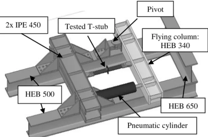
The test apparatus is depicted in Figure 2. The rig was designed according the current Standards [13, 3], providing resistance and stiffness for the proposed tests. Two main HEB 500 beams, placed horizontally are fixed to the reaction slab. These two beams are orthogonally bolted to a rigid reaction frame built from two IPE450, and in the other end to a HEB 650. The force is applied in the “flying column”. During the tests, it is mandatory that the deformation of this column be negligible; a welded section HEM 340, steel grade S355J2 ensures enough stiffness and resilience for this purpose. This column has an elastic moment capacity of 1438 KN.m, which is much higher than the value expected during the tests (maximum moment around 130 KN.m) and a very high flexural stiffness (EI) of 160 MN.m2.
Figure 2. Test layout developed at University of Coimbra.
The pneumatic cylinder was designed to work with a maximum operating pressure of P = 300 Bar. The schematic of the valve and pneumatic cylinder are described in Figure 3. Pneumatic cylinder Flying column: HEB 340 Tested T-stub Pivot HEB 500 2x IPE 450 HEB 650
Figure 3 – Valve and cylinder schematics The barrel of the cylinder was built with a cold drawn seamless steel tube, with an internal diameter of 125 mm, which result in a maximum force of 360 KN. In each end of the cylinder barrel there were end caps: one with a port for air intake into the cylinder chamber and other with a hole for the rod.
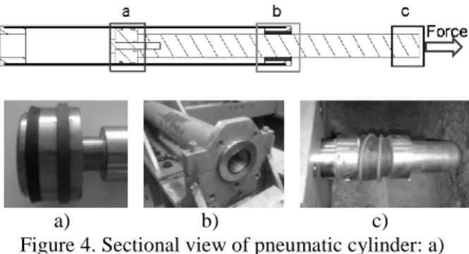
The piston, disc-shaped element within a cylinder connected to the rod, contains the seal and the piston guide (Figure 4a). The rod with 80 mm of diameter was chrome plated to provide better wear and corrosion resistance. In the end cap a special neck gland in phosphor bronze to guide the rod and reduce the friction (Figure 4b). A purpose built load cell was placed between the end rod and the “flying column”, with a spherical end to allow free rotation of the column and reduce friction, Figure 4c.
a) b) c)
Figure 4. Sectional view of pneumatic cylinder: a) piston and seals; b) end cap; c) load-cell. The sectional view of the quick open valve is presented in the Figure 5. The valve open when is activated through a hydraulic jack and whereas the air pass to the accumulator to the cylinder.
a)
b)
Figure 5. Sectional view of the quick open valve: a) closed; b) open.
3.3. Test procedure
The load was applied in the flying column through a pneumatic driven cylinder that was fixed to the reaction frame. Before applying the loading, the rod of the cylinder is in contact with the column. Initially the accumulator was filled with the predefined pressure; after, the quick open valve was opened and the air flows from the accumulator to the cylinder that induces the impact force in the “flying column”. The force-time depends mainly of the initial pressure and the flow rate of the nitrogen in the accumulator.
[F1]
3.4. Data acquisition and instrumentation
During the impact tests, force, displacements, accelerations and strains are measured. Because this type of tests occurs in a very small interval of time (hundredths of a second), specific equipment with large sample rate should be used. The data are recorded with a NI Compact DAQ 9172 chassis system, providing high performance for data acquisition. Chassis is connected to a host computer over USB; this type of data acquisition provides a very good relation signal-noise.
The acquisition of the accelerations are performed with a 4-Channel, ±5 V, 24-Bit IEPE Analogue Input Device, the strains with a Bridge Module 24 bits for quarter, half and full bridge measurements and the displacements with a 16 bits module, with 8 Channel Current Input.
The signal obtained from different types of measurements is processed in a virtual instruments program in Labview [14] environment. The program benefits from the rapid application and development of graphical programming.
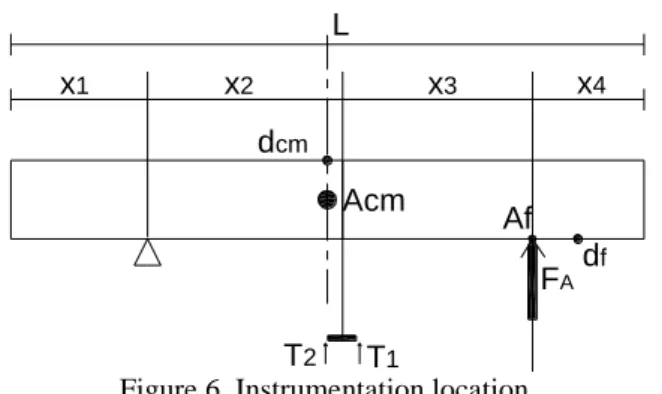
The displacements are measured at three points (Figure 6): in the middle of the column dcm, in boundary of the
application point of the force df, and in the T-stub (T1 and
T2). A laser triangulation sensors Riftek model
RF603/500, with a 9.4 Khz of bandwidth and a accuracy of +/- 0.5 mm, was used for these measurements. For measuring the accelerations, two piezoelectric accelerometers Brüel & Kjær model 4370 are used. The acceleration values are obtained for centre of mass of the “flying column” Acm (Figure 5) and in the point where
the force is applied Af (Figure 6).
The force FA is measured with a purpose built load cell,
located between the rod end of the cylinder and the “flying column” (Figure 4c). Figure 6 illustrates the instrumentation used during these tests.
Barrel Rod
Valve Hydraulic jack
Figure 6. Instrumentation location.
4. EVALUATION OF THE SPECIMEN
RESPONSE
Figure 7 depicts the free body diagram force-rotation for the tensile tests. The “flying column” consists in a second class lever pivot located at point (1); the load was applied in point (2) and the tested specimen is subjected to the force Ft at point (3). During quasi-static tests, the
distances X2 and X3 were steady and no inertia forces
were involved; so the static force equilibrium presented in the Equation 1 should be considered.
Figure 7. Free body diagram.
{𝑀 𝑅𝐴= 𝐹𝑡− 𝐹𝐴
𝑅(1)𝐴 = 𝐹𝑡× 𝑋2+ 𝐹𝐴× (𝑋2+ 𝑋3) (1)
where: Ft – force in the tested specimen; RA – reaction in
the pivot; FA – applied force by the cylinder; 𝑀𝑅𝐴 (1)
– moment in the pivot (1).
However, in the impact tests, it is required to calculate the inertial resistance moment of the column, due to the inertial forces involved during the impact. This calculus considers that: i) the distance X3 is variable during the
test and ii) the friction in the hinges and in the bearing supports are neglected.
The first moment of inertia measures the resistance of an object to an acceleration about an axis. For the calculation of the first moment of inertia, it is considered that the mass is uniformly distributed along the length of the column. Equation 2 represents this calculus; it is valid only when the rotation is performed on the centre of mass of the column. When the column rotates at a distance d from the centre of mass, the Parallel Axis Theorem should be applied, as shown in the Equation 3.
𝐼𝑐𝑚= ∫ 𝑟2× 𝑀𝑚 𝐿 𝑑𝑟 𝐿 2 −𝐿2 = 𝑚 3 × 𝐿× [ 𝐿3 8 − −𝐿3 8 ] = 1 12× 𝑚 × 𝐿2 (2) 𝐼 = 𝐼𝑐𝑚+ 𝑀 × 𝑑2 (3)
where: Icm – moment of inertia about its centre of mass m
– mass; L – length of the column; r - length variable; d- distance from the centre of mass to the pivot; I – moment of inertia about any axis parallel to the axis through the centre of mass.
The equilibrium of the dynamic force with inertial effects is represented in the equation 4.
𝐹𝑡(𝑡) = 𝐹𝐴(𝑡) − 𝐹𝐼(𝑡) + 𝑅𝐴(𝑡) (4) where: Ft – force in the tested specimen: FA – applied
force by the cylinder; FI – force of inertial; RA – reaction
in the pivot.
By taking into account the centre of rotation and the location of the centre of mass, the dynamic moment equilibrium at pivot is calculated (location (1) at Figure 7), by equations 5 and 6.
𝐹𝑡× 𝑥2= 𝐹𝐴× (𝑥2(𝑡) + 𝑥3(𝑡)) − 𝐹𝐼
× 𝑥𝑐𝑚− 𝑀𝐼(𝑡) (5)
𝐹𝑡× 𝑥2= 𝐹𝐴× (𝑥2(𝑡) + 𝑥3(𝑡)) − 𝑚
× 𝑧𝑐𝑚̈ (𝑡) × 𝑥𝑐𝑚− 𝐼 × 𝜃̈ (6) where: X2(t) - distance X2 in time; X3(t) - distance X3 in
time; FI – force of inertia; Xcm – distance of the centre of
mass to the pivot; MI - moment of inertia about any axis
parallel to the axis through the centre of mass; 𝑧𝑐𝑚̈ – acceleration of the centre of mass of column.; I – inertia of the column; 𝜃̈ – rotational displacement of the column. The rotation of the column (θ) could be calculated based on the laser displacement gauge data (location df in
Figure 5), using the Equation 7, or by double integration of the column acceleration recorded at point Af in Figure
5, as represented by Equation 8. 𝛩(𝑡) = 𝑡𝑎𝑛−1( 𝑍3
𝐿 − (𝑋1+ 𝑋4(𝑡))) (7) where: Z3 – displacement in the point of load FA; L –
length of the column.
𝛩(𝑡) = 𝑡𝑎𝑛−1[ (∬ 𝑎𝑡𝑑𝑡𝑑𝑡) 𝐿 − (𝑋1+ 𝑋4(𝑡))] (8) FA df Af Acm T1 T2 x1 x2 x3 x4 L dcm X1 X2 X3 X4
R
AF
tF
A (1) Z2 Z3 Z1 Center of mass r (1) (3) (2) Lwhere: at – acceleration recorded by the accelerometer.
Moreover, for the rotational acceleration (𝜃̈), two different ways can be used for the calculus: i) double differentiation of the laser displacement gauge data (equation 9), or ii) using accelerometer readings at at
(equation 10).
𝜃̈(𝑡) = 𝑑
2𝑧
3(𝑡)
𝑑𝑡2 (9)
where: Z3 – displacement in the point of load FA; L –
length of the column.
𝜃̈(𝑡) =𝑎𝑓
𝑅 (10)
where: af – acceleration of the column at point (2); R –
length X2 + X3(t).
5. CALIBRATING TESTS
In order to calibrate and benchmark the experimental system, a series of experimental tests were performed. The experimental layout corresponds to the one illustrated in Figure 2, but without attached specimen (identified as the blue detail). During these tests, the load was applied in the “flying column” that was free to rotate. A maximum translation around 250-300 mm is allowed at the end of the column in line with the cylinder at point df (Figure 6).
The tests were performed with three different pressures: 10, 30 and 50 Bar. These values of pressures allowed studying the influence of the pressure in the variation of the time application, and the corresponding value of the applied load.
For each pressure in these tests, the applied load FA, at
point (2) (Figure 6) vs time is depicted in Figure 8. As expected, the design system is able to apply high values of dynamic loads in a short interval of time. It is also observed that the maximum applied load increases with the increase of the pressure, while the time where it maximum force was reached, decreases.
Figure 8. Applied load vs time.
Figure 9 presents the measured column translation displacement at point df (Figure 6). The time when the
maximum displacement is reached, decreases with the increase of the pressure value. For example, 35.6 mm, 163.1 and 290 mm are reached in 0.1s for 10, 30 and 50 Bar, respectively; non linearity between applied pressures and the corresponding displacements is obtained.
Figure 9. Column translation displacement at point df.
For the test at 50 Bar, Figure 10 presents the acceleration of the “flying column” vs time at point of application of load FA (Figure 6). It can be observed that the force is
applied between 0 and 0.1s, and a maximum value of acceleration of 30 m/s2 is reached after 0.06 s. Beyond
this point, occurred a deceleration that is result of combined effects: i) inertia; ii) friction and iii) structure response. After 0.1s, the column has reached the end-stop and the previous equations of free body assumptions (Equation 6) are no longer valid.
Figure 10. Column acceleration at point of application of load (test at 50 Bar).
Figure 11 compares the displacement of the column at point df (Figure 6) obtained by the two methods described
in Section §3: i) using the laser data and ii) by the integration of the acceleration. The results showed a good correlation between both methodologies. Note that the acceleration obtained through the accelerometer, have been filtered with high pass and low pass filters; for that system, the frequencies were assessed with the numerical model for the system [15].
Figure 11. Validation of the instrumentation, 50 Bar test.
6. TEST ON T-STUB 6.1. Introduction
In this chapter are presented the results of the tensile test of a T-stub. A T-stub (Figure 12) is used to evaluate the behaviour of the tensile components responsible for the main source of the deformability of the joint. The experimental layout is illustrated in Figure 2.
Figure 12. T-stub identification [16].
In the test, the load applied at the “flying column” reaches a dynamic force up to collapse of the specimen. Concerning the instrumentation, the acceleration, displacements and applied force are recorded.
6.2. Geometrical characteristics of the specimen The tested T-stub comprises two plates, the flange and the web, welded by means of a continuous 45º fillet (aw),
Figure 13. The thickness of the flange plate is 5 mm and for the web plate is 10 mm. The flange is bolted through two bolts M20, grade 8.8 fully threaded.
Figure 13. T-stub geometry 6.3. Results
Figure 14 presents the applied load vs time in the “flying column” at point (2) (Figure 7). The maximum force (40 kN) is reached after 0.2 s, approximately.
Figure 14. Applied load vs time
The acceleration vs time (filtered and non-filtered signals) are presented in Figure 15. The high frequencies were filtered to reduce the noise of the signal, and the filter was calibrated based on the power spectrum of the accelerogram. Initially the acceleration rises up to 5 m/s2,
but during the process of deformation of the T-stub flange, a decrease in the acceleration is measured. The values of the maximum acceleration are lower, as expected, than the ones measured during the calibrating tests.
Figure 15. Acceleration at point af (Figure 6) in the
“flying column”.
Figure 16 depicts the inertial force due the translation of the center of mass of the column. Following, the inertial resistance moment presented in the Figure 17, is calculated through the product of the accelerogram presented in Figure 14 and the first moment of inertia of the column (Equation 3).
Figure 16. Inertial force due the translation of the centre of mass of the “flying column”.
170 105
30
30
Top view Lateral view
Weld -15 -10 -5 0 5 10 15 0 0.05 0.1 0.15 0.2 0.25 Ac c elerat ion (m /s 2) Time (s)
Acceleration non filtered Acceleration filtered -3 -2 -1 0 1 2 3 0 0.05 0.1 0.15 0.2 0.25 Inert ial forc e(KN ) Time (s) aw
Figure 17. Resistant moment of inertia of the “flying column”.
The force in the T-stub is depicted in the Figure 18; this force is calculated according to Equation 5, taking into account the inertia effects previous presented in Figures 16 and 17. The maximum force applied to the T-stub is 81 KN at 0.17 s. After 0.2 s, the force reaches the static equilibrium.
Figure 18. Force applied in the T-stub.
The deformation of the T-stub is measured by the laser deflectometers placed in the location T1 and T2 (Figure
6), and the average of the two measured values is presented in Figure 19: the grey curve corresponds to the measured signal and the black curve corresponds the linearized value. In the first stage of the test (up 0.05 s), small deformation rate is observed in the T-stub; after that, the deformation rate increases rapidly.
Figure 19. Deformation on the T-stub.
Considering the force in the T-stub (Figure 18) and its deformation (Figure 19), force-deformation curve is
presented in Figure 20. A maximum deformation of 15 mm is reached for 81 KN.
Figure 20. Force- deformation curve of the T-stub. The deformed shape of the T-stub after the test is presented in the Figures 21 and 22; yielding of the flange in the welded zone and ovalization of the bolts are observed. No failure of the bolts or crack in the weld occurred during the test.
Figure 21. T-stub deformation after test.
Figure 22. Ovalization of the holes of the bolts after test.
7. CONCLUSIONS
This paper described the design, calibration and validation of the experimental system to apply high rates of loading. The results of the calibrating tests showed that the system is capable to apply and simulate an impact force in specimens to failure; the shape of the force and acceleration, in terms of duration and magnitude are in accordance of the objectives. The results from data acquisition system were accurate and reliable.
Concerning the response of the T-stub when subject to rapidly applied dynamic loads, the results showed that, the provided equations and the instrumentation system -4 -3 -2 -1 0 1 2 3 0 0.05 0.1 0.15 0.2 0.25 R es is tant m om ent of iner tia (KN .m ) Time (s) 0 10 20 30 40 50 60 70 80 90 0 0.05 0.1 0.15 0.2 0.25 F orc e (KN) Time (s) 0 2 4 6 8 10 12 14 16 18 0 0.05 0.1 0.15 0.2 0.25 D ef orm at ion (m m ) Time (s)) 0 10 20 30 40 50 60 70 80 90 0 5 10 15 20 F orc e (KN ) Deformation (mm) 15 mm
are capable to determine the inertial effects of the loading and its components with accuracy.
Regarding the mode of failure of the T-stub, it corresponds to the mode 1: development of two plastic hinges, one at the bolt axis due to the bending moment induced by the prying forces and another next to the weld toe. Although the high level of deformation in the T-stub, no failure was observed.
These experimental results, is part of the framework of the ImpactFire research project, and they are being used to calibrate and validate numerical and analytical models for characterisation of beam-to-column steel connections under impact loads.
ACKNOWLEDGEMENTS
The authors acknowledge the financial support of the Portuguese Foundation for Science and Technology under the research project PTDC/ECM/110807/2009.
REFERENCES
[1] British Constructional Steelwork, A. and I. Steel Construction, Joints in steel construction: simple connections 2002, Ascot: Steel Construction Institute.
[2] IMPACTFIRE Project PTDC/ECM/110807/2009. [3] EN 1993-1-8, Eurocode 3: Design of steel structures
Part 1-8: Design of joints, Brussels: European Committee for Standardization, 2005.
[4] Barata, P., Rigueiro, C., Santiago, A. and Rodrigues, J. P., Caracterização do cenário de impacto em estruturas metálicas, VIII Congresso Construção Metálica e Mista, 2011, pp. II-325-334.
[5] EN 10045-1, Metallic materials, Charpy impact test, part 1: test method, 1990.
[6] ASTM E208 06, Standard Test Method for Conducting Drop-Weight Test to Determine Nil-Ductility Transition Temperature of Ferritic Steels, 2012.
[7] Mechanical Behaviour of Materials Volume II: Viscoplasticity, Damage, Fracture and Contact Mechanics Series: Solid Mechanics and Its Applications, Vol. 58
[8] Shukla, A., Ravichandran, G., & Rajapakse, Y. Dynamic failure of materials and structures. Springer, 2010.
[9] Puzak, P.P., and Pellini, W. S., "Standard Method for NRL Drop-Weight Test," NRL Report 5831, Naval Research Laboratory, 1962.
[10]Bambach, M.R., Jama, H., Zhao, X.L., Grzebieta, R.H. Hollow and concrete filled steel hollow sections under transverse impact loads, Engineering Structures, Vol. 30 , 2008, pp. 2859–2870.
[11] Zeinoddini, M., Parke, G.A.R., Harding, J.E. Axially pre-loaded steel tubes subjected to lateral impacts: an
experimental study, International Journal Impact Engineering, Vol. 27, 2002, pp. 669–690.
[12] Stoddart, E.P., Byfield, M.P., Davison, J.B., Tyas, A., Strain rate dependent component based connection modelling for use in non-linear dynamic progressive collapse analysis, Engineering Structures, Volume 55, 2013, pp 35-43.
[13] EN 1993-1-1, Eurocode 3: Design of steel structures. Part 1-1: General rules and rules for buildings, European Committee for Standardization, 2006. [14] King, R. H., Introduction to data acquisition with
LabVIEW, McGraw-Hill, 2013.
[15] Ribeiro, J., Santiago, A. e Rigueiro, C., Análise dinâmica não-linear de ligações viga-pilar aparafusadas com placas de extremidade, IX Congresso Construção Metálica e Mista, 2013, pp. II-337.
[16] Girão Coelho, A.M., Bijlaard, F.S.K., Gresnigt, N. and Simões da Silva, L. - Experimental assessment of the behaviour of bolted T-stub connections made up of welded plates, Journal of Constructional Steel Research, vol.60, 2004, p. 269-311.