Engenharia
Beach-Volumes:
Design of Software & Hardware
Miguel Alexandre Vaz Cordeiro
Dissertação para obtenção do Grau de Mestre em
Engenharia Informática
(2
ociclo de estudos)
Orientador: Prof. Doutor Rui Manuel da Silva Fernandes
Acknowledgement
I see this project as the conclusion of another cycle that, although individual had the support of several people. I want to express my gratitude to all of them.
First of all, I would like to thank my family, especially my parents, for all the support they gave me during this stage of my life, and the pride they feel for me.
A big thanks to my girlfriend for having followed me in this stage of my life and for under-standing, supporting and helping to overcome all the dif culties I had in this path.
I also would like to thank my dissertation advisor, Professor Rui Manuel da Silva Fernandes, for his time availability and for the information and advices he transmitted, allowing me to get the knowledge and skills necessary to successfully complete the project's work plan. I also would like to thank the project SingSubs - Monitoring of Subsidence in Singapore, a collaboration with Tropical Marine Scienti c Institute (TMS), part of the National University of Singapore, for the research grant they provided me, allowing the development of this project in the last year.
Finally, I want to thank all my friends and laboratory colleagues especially, João Apolinário and Machiel Bos for the help they have given me over this year. You know, in one way or another, are a part of this work.
Abstract
The main objective of the research work described in this manuscript was to develop methods (hardware/software) for three-dimensional data acquisition in order to perform morphological analysis in sandy shore environments. This system, when concluded, intends to estimate the volumetric variations in beaches being eroded at high rates, directly contributing for studies focused on the protection of the coastline. This work is particularly focused on the development of software to estimate the 3D positions using a dedicated low-cost hardware device that was also developed in the framework of this project.
Several methods have been used to study these phenomena, such as classical topography by surveying discrete points with the utilization of theodolites and/or total stations that are highly time-consuming. Other methods that start recently being used, like terrestrial or airborne LiDAR, are very costly and are not suitable to be used in many locations due to governmental requirements (like permits, environment, and security issues). Similar limitations also occur with Mobile Mapping Systems (MMS) with laser scanners that permit the survey when the vehicle is moving on the beach.
In order to minimize the issues presented by the techniques described above, it was devel-oped a simple, economic, ef cient and accurate system that can be used to study the erosion phenomena in coastal area. This system should allow one to acquire accurate GNSS positioning data on beaches, using a simple acquisition device in order to enable the creation of a three--dimensional surface of the study area, which temporal variation can permit to quantify the erosion rates. This system is formed by an acquisition device, a GNSS receiver and antenna, and a Android Tablet/Smartphone that allows us to collect the antenna attitude from it's in-ternal orientation sensors. To collect information from the angles of the sensors, an Android application was developed. With the Tablet/Smartphone attitude angles, it is possible to cor-rect the GNSS observations in order to obtain the vertical position - a dedicated C# application was developed with this objective. This corrections allows the creation of surfaces that ac-curately represent the terrains where the observations were conducted. In the future, using several observations at different times, it is possible to study the variations of sand volumes of the surveyed beaches and analyse the morphological variations. Some preliminary tests were performed concerning the creation of the surfaces, in order to evaluate the internal accuracy of the entire system. For this goal, we developed several scripts, using GMT (Generic Mapping Tools), that can also be used in the future to calculate the variations of the beach volume.
In this respect, the results of some tests carried out to evaluate the accuracy of the developed technology are presented. In particular, by analysing the deviations with respect to a reference surface and by evaluating the sensitivity when measuring on an irregular surface.
Keywords
Resumo Alargado
O principal objetivo do trabalho de investigação descrito neste manuscrito foi, desenvolver métodos (software/hardware) para aquisição de dados em três dimensões, de forma a realizar a análise morfológica em ambientes de costa arenosa. Este sistema, quando estiver concluído, pretende estimar as variações volumétricas em praias que estão a ser erodidas a taxas elevadas, contribuindo diretamente para estudos voltados para a proteção da zona costeira. Este trabalho está focado principalmente no desenvolvimento de software para estimar as posições em 3D utilizando um dispositivo de hardware de baixo custo dedicado que também foi desenvolvido no âmbito deste projecto.
Têm sido utilizados vários métodos para estudar estes fenômenos, tais como topogra a clás-sica através do levantamento de pontos discretos, com a utilização de teodolitos e/ou estações totais que são altamente demoradas. Outros métodos que começam recentemente a ser lizados, é o LiDAR terrestre ou aéreo, são muito caros e não são adequados para serem uti-lizados em muitos locais, devido a exigências governamentais (como licenças, meio ambiente e questões de segurança). Também ocorrem limitações semelhantes com o Mapeamento de Sistemas Móveis (MMS) com scanners a laser que permitem o levantamento, quando o veículo estiver em movimento na praia.
Para minimizar os problemas apresentados pelas técnicas acima descritas, desenvolveu-se um sistema simples, económico, e ciente e preciso que possa ser utilizado para estudar os fenómenos da erosão da zona costeira. Este sistema deve permitir adquirir dados de posiciona-mento GNSS precisos nas praias, utilizando um dispositivo simples de aquisição, para permitir a criação de uma superfície tridimensional da área de estudo, o que pode permitir a variação temporal para quanti car as taxas de erosão. Este sistema é formado por um dispositivo de aquisição, um receptor GNSS e uma antena e um Tablet/Smartphone Android que nos permita recolher a atitude da antena apartir dos sensores de orientação internos. Para a recolha da informação a partir dos ângulos dos sensores, foi desenvolvida uma aplicação Android. Com os ângulos da atitude do Tablet/Smartphone, é possível corrigir as observações GNSS, para obter uma posição vertical - foi desenvolvida uma aplicação C# com este objectivo. Esta correcção permite a criação de superfícies que representam com precisão os terrenos onde foram real-izadas as observações. No futuro, utilizando várias observações em momentos diferentes, é possível estudar as variações do volume da areia das praias estudadas e analisar as variações morfológicas. Foram realizados alguns testes preliminares sobre a criação de superfícies, para avaliar a precisão interna de todo o sistema. Para este objectivo, foram desenvolvidos alguns scripts, utilizando o GMT (Generic Mapping Tools), que também podem ser utilizados no futuro, para calcular as variações de volume da praia.
Assim, são apresentados os resultados de alguns testes realizados para avaliar a precisão da tecnologia desenvolvida. Em particular, através da análise dos desvios em relação a uma superfície de referência e pela avaliação da sensibilidade na medição sobre uma superfície irregular.
Contents
Contents xi
List of Figures xiii
List of Tables xv 1 Introduction 1 1.1 Motivation . . . 1 1.2 Description of Problem . . . 1 1.3 Approach . . . 2 1.4 Objectives . . . 2 1.5 Main Contributions . . . 4 1.6 Organization of Dissertation . . . 5
2 Literature Review and Explication of the Context 7 2.1 Kinematic GNSS . . . 7
2.2 Classical Methods To Acquire Kinematic GNSS Data . . . 7
2.2.1 Total Station . . . 7
2.2.2 Light Detection And Ranging (LiDAR) . . . 8
2.2.3 Mobile Mapping Systems(MMS) With Laser Scanners . . . 10
2.2.4 Summary . . . 11
2.3 Android Applications to Acquire Gyroscope Data . . . 11
2.3.1 Physics Toolbox Gyroscope . . . 11
2.3.2 Sensor Display & Logging . . . 12
2.3.3 Sensor Kinetics Pro . . . 12
2.3.4 Data Sensors . . . 12
2.3.5 Fused Linear Acceleration . . . 13
2.3.6 Sensor Log . . . 13
2.4 Android Application "GPS Time" . . . 13
2.5 Trimble Business Center . . . 14
3 Requirement Analysis 15 3.1 General Description - System Perspective . . . 15
3.2 Technologies Utilized . . . 15
3.2.1 Microsoft Visual Studio . . . 16
3.2.2 Android Studio . . . 16
3.2.3 Trimble Business Center . . . 16
3.2.4 Generic Mapping Tools (GMT) . . . 17
3.2.5 Functional Requirements . . . 17
3.2.6 Non-Functional Requirements . . . 17
3.2.7 Interface Requirements . . . 17
3.2.8 Restrictions . . . 17
6 Conclusions and Future Work 41
6.1 Conclusions . . . 41
6.2 Future Work . . . 43
References 45 A 49 A.1 User Manual . . . 49
A.1.1 Organization of the Manual . . . 49
A.2 Acquire GNSS and Tablet/Smartphone Data . . . 49
A.3 Data Processing . . . 53
A.3.1 Trimble Business Center . . . 53
A.3.2 Convert Coordinates . . . 57
A.3.3 Veri cation of GNSS and Tablet/Smartphone Data . . . 57
A.4 Correction Coordinates . . . 57
A.4.1 Air2Ground . . . 57
A.5 Surfaces Computations . . . 59
B 61 B.1 GMT Scripts . . . 61 B.1.1 txt2srf . . . 61 B.1.2 create_surf . . . 62 B.1.3 suf_diff . . . 64 B.1.4 surf_all . . . 68 B.1.5 parameters . . . 69 B.1.6 GMT_abso . . . 70
List of Figures
1.1 Comparison of beach erosion and re-nourishment [2] . . . 3
1.2 Device developed to acquire the GNSS and attitude observations . . . 3
1.3 Methodologies Work ow . . . 4
2.1 Total Station . . . 8
2.2 Terrestrial and Airborne LiDAR . . . 9
2.3 Mobile Mapping Systems(MMS) With Laser Scanners . . . 11
2.4 GPS Time Application . . . 14
3.1 Use Case Diagram of the User . . . 18
4.1 Acquisition Device . . . 19
4.2 Android Application "GyroData" - Main Menu . . . 20
4.3 Android Application "GyroData" - Add Note . . . 21
4.4 Mini-Output File of the GyroData Application . . . 22
4.5 Function "onSensorChanged(SensorEvent event)" . . . 22
4.6 Tablet Reference Frame . . . 23
4.7 TBC Mini-Output File - Coordinates Points . . . 24
4.8 TBC Mini-Output File - Time of each Point . . . 24
4.9 Ellipsoidal and Rectangular Coordinates . . . 25
4.10 Equations of ECEF to Local Coordinates Transformation . . . 25
4.11 Rotation Matrix to East, North, Up . . . 26
4.12 Rotation Matrix to X, Y, Z . . . 26
4.13 Air2Ground Application . . . 26
4.14 Rotation Around Axes X Y Z . . . 27
4.15 Rotation Matrix . . . 27
4.16 Correction Coordinates Equation . . . 28
4.17 Important print of the TabletGPSFileFormat Method . . . 29
4.18 Interpolation Example . . . 30
5.1 Surface with Smartphone 1 (x and y-axis are the east and north in meters). . . . 33
5.2 Surface with Smartphone 2 (x and y-axis are the east and north in meters). . . . 34
5.3 Differences between Surfaces of Smartphone 1 (x and y-axis are the east and north in meters). . . 34
5.4 Differences between Surfaces of Smartphone 2 (x and y-axis are the east and north in meters). . . 35
5.5 Tested Area with 2 tracks at different colors (x and y-axis are the east and north in meters). . . 36
5.6 Differences between points within 4 cm of distance of each other in two different tracks (x and y-axis are the east and north in meters). . . 37
5.7 Difference between one surface and the average surface (x and y-axis are the east and north in meters). . . 37
5.8 Beach Area with 2 tracks at different colors (x and y-axis are the east and north in meters). . . 38
A.8 Create New Project in TBC. . . 53
A.9 The New TBC Project. . . 53
A.10 Import Files. . . 54
A.11 Project Settings. . . 54
A.12 GNSS data processing. . . 55
A.13 GNSS data processing results. . . 55
A.14 GNSS data processing results. . . 55
A.15 Export Data. . . 56
A.16 Export VectorList. . . 56
A.17 VectorList Example. . . 56
A.18 Air2Ground Application. . . 58
List of Tables
4.1 GPS Time Application Test. . . 28 5.1 Test the Pitch and Roll error. . . 35
Acronyms List
AJAX Asynchronous JavaScript and XML ARFF Attribute-Relation File Format
ASCII American Standard Code for Information Interchange CSS Cascading Style Sheets
DEM Digital Elevation Model DR Dead Reckoning DSM Digital Surface Model DTM Digital Terrain Model ECEF Earth-Centered Earth-Fixed
EDM Electronic Distance Measurement ENU East North Up
FIG International Federation of Surveyors GMT Generic Mapping Tools
GNSS Global Navigation Satellite System GPS Global Positioning System
HTML HyperText Markup Language
ICEUBI International Conference on Engineering of University of Beira Interiror IDE Integrated Development Environment
IDL Instituto Dom Luis
IMU Inertial Measurement Unit INS Inertial Navigation System LiDAR Light Detection And Ranging
MMS Mobile Mapping Systems RAM Random Access Memory
RINEX Receiver Independent Exchange Format RMS Root Mean Square
SEGAL Space and Earth Geodetic Analysis Laboratory TBC Trimble Business Center
TLS Terrestrial Laser Scanning TRU Topcon Receiver Utility
TS Total Stations
UBI Universidade da Beira Interior UML Uni ed Modeling Language USB Universal Serial Bus
WGS84 World Geodetic System 1984 XML Extensible Markup Language
Chapter 1
Introduction
1.1 Motivation
The main goal to select the subject of this dissertation, was my motivation to work on the eld of Geodesy, which is an area where computer science and technology are developing together and where I would like to develop work during my professional activity in the future.
Coastal hazards (like oods and tsunamis) are a major problem all over the world, including Portugal and Singapore, and can cause a large number of deaths and destruction. I think it is important to contribute to the development of technological solutions that allow the ef cient monitoring the state of the coast line in a period of time. Another important element that contributed for choosing this project was the fact of being integrated into a research grant where I had the opportunity to expand my knowledge in various areas.
After a previous research of the used methods, was possible to conclude that all of them had serious problems and it was important to contribute with a new solution. Some classical methods such as the use of Total Stations are highly time-consuming. Other methods that started recently being used, as land or air LiDAR, are very expensive and are not suitable to use in many places, because of government requirements (such as licenses, environmental and safety issues). Similar limitations also occur with mobile mapping systems (MMS) with laser scanners that allow the survey, when the vehicle is in motion on the beach (the geo-referencing is done by GNSS + IGS).
All of this gave me a great motivation to perform this dissertation where I pursued to build a system with less restrictions and cheaper than existing systems.
1.2 Description of Problem
Beach volume changes are de ned as the mass of sand that enters or leave an area of interest over time. Since it is customary to only make measurements a few times per year, for example in summer and winter, one only can observe the total gain or loss of sand between these measurements.
The volume of the beach is computed by constructing a very high resolution digitial terrain model (DTM) of the area. This DTM can be converted into an estimation of the volume of sand of the beach. The problem is how one can construct an accurate DTM of the beach in a cost effective manner.
is that we use the tilt-meters of a relatively cheap tablet to correct for this problem.
In order to compute the volumetric variations of the sandy surfaces, a simple, fast and eco-nomic system was developed based on an acquisition device with a GNSS receiver and antenna and an Android Tablet/Smartphone. It was developed several applications to complement this innovative system. The rst developed application was GyroData, an Android application, that collects the attitude angles of the Tablet/Smartphone (Euler Angles) from the internal gyro-scope. With these collected angles it is possible to correct the position of the GNSS antenna in order to precisely calculate the 3D surface from the observed tracks.
To process the acquired GNSS data, the Trimble Business Center (TBC) software was used in order to obtain all observed points along the study area. This software was used because it was available in our Lab, however other commercial software's could have been used to process the GNSS data. After the data processing, it will be necessary to compute the three-dimensional surfaces that represent the observed terrain. Some Linux scripts were developed that in the future can also be used to evaluate the sandy volumetric conclusions.
We started by performing the analysis of the requirements in order to design the system. We will discuss the features, concepts, GNSS basics, programming languages and the IDE's used for the development of the system. Finally, we discuss the tests done.
1.4 Objectives
This dissertation is integrated in a research scholarship in the framework of the project SingSubs - Monitoring of Subsidence in Singapore. It was carried out at SEGAL (Earth & Space Geodetic Analysis Laboratory), a laboratory that it is a scienti c collaboration between UBI (University of Beira Interior) and IDL (Instituto D. Luis - University of Lisbon).
The main objective of this project is to develop methods (software and hardware) for data acquisition (vertical pro les) in order to perform morphological analysis in sandy shore environ-ments to detect erosion (or accumulation) rates, which can help to mitigate coastal hazards. Figure 1.1 represents a comparison of beach erosion and re-nourishment in Happisburgh on the East Anglian coast in England, between 1996, 2006 and 2012 [1] [2].
Figure 1.1: Comparison of beach erosion and re-nourishment [2]
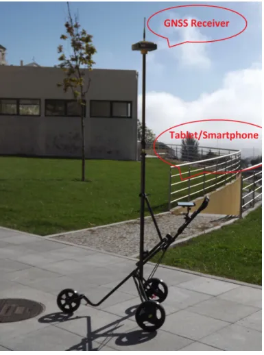
In terms of hardware, we intend to developed a system that can cover large areas in a relatively short period, with suf cient accuracy. The system is based on the use of a lightweight device that contains a structure of three wheels with a GNSS receiver and antenna and a tablet solidly attached to the structure. Figure 1.2 shows the developed device.
Figure 1.2: Device developed to acquire the GNSS and attitude observations
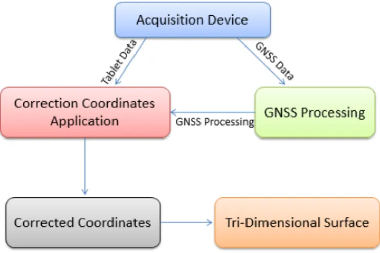
The GNSS device is used to obtain the 3D positions which are referred to the surface by applying known offsets and corrections estimated using the information provided by the tablet. Figure 1.3 shows the work ow of the methodologies used to compute the three-dimensional surface using the integrated system discussed in this dissertation.
Figure 1.3: Methodologies Work ow
This methodology is composed by the acquisition device that collects GNSS and Tablet data to process the coordinates of the observed points. After the observed GNSS data processing, the coordinates are corrected using the developed application and using the collected attitude angles. The output of the application is a .txt le with the corrected coordinates of each point and with this information it is possible to compute the three-dimensional surface.
The long term objective is to use this prototype to see if there have been any signi cant changes in the volume of existing sand along the beaches of Singapore, which may have direct consequences on the protection of the coastline.
1.5 Main Contributions
The main contributions of this dissertation are here presented:
• Construction of a lightweight equipment, low cost and easy to carry for acquiring GNSS data and attitude angles of the GNSS antenna.
• Development of a set of applications that permit to estimate volumetric variations using the developed device. In the end, this integrated application can also be used with other devices since the observations are made available in the right formats.
During the course of this dissertation the following conference papers were written:
• Pecha Kucha Presentation with the title "Low-Cost Integrated GNSS/INS for Surface
Varia-tion Monitoring" in 1st FIG Young Surveyors European Meeting (http:// gysn.ordemengenheiros.pt/pt/). • An article with the title "Low-Cost Integrated GNSS/INS for Beach Variation Monitoring"
1.6 Organization of Dissertation
This report is divided into chapters.
Chapter 1 - Introduction The rst chapter is an introduction to the topic of the
disserta-tion, outlining the motivations that led to the development of the same, the objectives to be achieved and nally the approach taken throughout the development.
Chapter 2 - Literature Review and Explication of the Context
In this chapter a reference is made to existing systems which collect Kinematic GNSS data with the same purpose for which the implemented system is proposed.
Chapter 3 - Requirements Analysis
In chapter 3 a super cial description of the operation of the system is made, and information about the requirements and restrictions of each developed module is presented.
Chapter 4 - System Development
Chapter 4 presents a detailed explanation of all the methods used to develop each of the modules of the system.
Chapter 5 - Test and Results
Charter 5 presents some tests made to the system in different terrain types and their respec-tive results.
Chapter 6 - Conclusion and Future Work
Presents the overall conclusions of the development of the project, as well as a description of what can be added to this work.
References
Appendix A - Attachments - User Manual
Chapter 2
Literature Review and Explication of the Context
2.1 Kinematic GNSS
The concept of relative kinematic positioning using GNSS carrier phase observations was de-scribed by Remondi [3]. After that, several methods were developed to implement pseudo-matic and semi-kinepseudo-matic GNSS surveying, all based on static initializations [4] [5]. Purely kine-matic GNSS methods require the computation of the position of an object in permanent motion, without static initialization.
With the technological advances in hardware and software, several accurate kinematic GNSS precise relative positioning solutions started to be provided by private or governmental agen-cies. Kinematic GNSS positioning with centimetre accuracy is now a standard product available for a wide range of applications. However, all these solutions are con ned to a limited range from a reference station (around 20-40 km) or from a network of stations.
2.2 Classical Methods To Acquire Kinematic GNSS Data
In the development of any system, it is important to identify the required features and functionalities. One approach is to analyze similar products that have comparable functions in order to evaluate the pros and cons.
2.2.1 Total Station
The conventional terrestrial survey methods, such as total station (TS), can be used to per-form beach monitoring in a stand-alone mode or by supporting kinematic GNSS. Total station (TS) instruments combine an EDM (Electronic Distance Measurement), an electronic digital theodolite, and a computer in one unit. These devices can automatically measure horizon-tal and vertical angles, as well as distances, and transmit the results in real time to a built-in computer.
The horizontal and vertical angles and slope distance can be displayed, and then upon key-board commands, horizontal and vertical distance components can be instantaneously com-puted from theses data and displayed.
If the instrument is oriented in direction and the coordinates of the occupied station are input to the system, the coordinates of any point sighted can be immediately obtained. This data can all be stored within the instrument, or in an automatic data collector, thereby eliminating manual recording [9].
Figure 2.1: Total Station
Local precision is one of the biggest advantages a total station has over a GNSS but, total station has more disadvantages than advantages. Total station are highly time-consuming, still requires several days to monitor a beach which is expensive because of the man-hours involved. Regarding the accuracy of a total station, it is dependent on instrument type and it is highly dependent on the levelling of the instrument.[10].
2.2.2 Light Detection And Ranging (LiDAR)
The LiDAR technology determines the distance between ground objects and sensors by mea-suring the time a pulse of transmitted energy takes to return to the LiDAR sensor. When coupled with a ground referencing system, LiDAR sensors make dense, geo-referenced point elevation measurements [12] [13]. Compared with traditional surveying and mapping systems, includ-ing photogrammetric systems, LiDAR technology provides a fast and accurate alternative [14] [15] for mapping large areas at high resolution and is gradually being adopted as the primary technique to generate Digital Elevation Models (DEMs) [16] [17]. The United States and some European countries have begun to utilize LiDAR systems to generate regional to national DEM products [12] [18] [19].
LiDAR techniques are arguably superior to traditional methods (e.g., photogrammetric tech-niques or automated image matching and elevation extraction techtech-niques) for generating DEMs for at least ve related reasons, as described by Reference [11]. First, the dense LiDAR point clouds enable generation of highly accurate, high resolution DEMs. Second, surface features can be extracted based on a height context analysis of the LiDAR points [20] [21], enabling accu-rate mapping of surface features like buildings, trees, and even power lines and pipelines [20] [22]. Additionally, a high density dataset allows users to apply a multi-scale or multi-resolution strategy of feature identi cation [21]. Third, it is easier to identify slight elevation changes using dense LiDAR point clouds, making it easier to map regions with little textural variations, including variations in the surface of vegetation canopies [20] [23]. Fourth, vegetation canopy
structure can be determined because LiDAR pulses penetrate the canopy and create multiple returns [24] [25]. Different multiple return patterns during different seasons can also facili-tate vegetation classi cation [26]. Lastly, LiDAR can be used to map ground elevations even in regions of dense vegetation because of multiple returns [20].
Figure 2.2: Terrestrial and Airborne LiDAR
2.2.2.1 Terrestrial LiDAR
The terrestrial laser scanning (TLS) instruments are a valuable asset for a variety of real-world problems. Beside their traditional use in areas such as digital terrain modelling, geological exploration, surveying, archeological and architectural documentation, they have found appli-cations in forensics and crime scene investigations, deformation monitoring of dams, buildings and landslides, and more recently for scanning movie sets. For many applications of TLS, it is assumed that the point cloud is error-free. Although this is far from reality, numerous efforts have attempted to produce more reliable and accurate point clouds. New and improved lters and measurement algorithms have limited a great deal of outliers and noise in the point cloud. Typical TLS projects involve grouping common points to model a surface or object to reduce the effect of random noise. Modern TLS instruments behave much like total stations; how-ever their systematic errors cannot be eliminated by taking direct and rhow-everse measurements. Instead, users usually have to rely on the manufacturer's black box instrument calibration. The manufacturer's calibration has been shown to be an effective method for improving the scanner's observation precision, but it has also been demonstrated that point-based user self-calibration can further reduce the standard deviation of the scanners observations [27].
2.2.2.2 Airborne LiDAR
Airborne Lidar is an emerging technology and relying on the accuracy of GPS and IMU compo-nents in the system, it can produce data of high resolution and accuracy in both horizontal and vertical directions. With this information, researchers can analyse tree volumes, building struc-tures and create 3D urban models. Although applications of Lidar data vary, all these modelling
Airborne Lidar is the fastest of all mentioned methods, but ight time is expensive and therefore only suitable for large areas of hundreds of kilometres.
2.2.3 Mobile Mapping Systems(MMS) With Laser Scanners
Mobile mapping combines absolute and relative positioning devices and sensors to locate features in a global reference system [30]. The absolute positioning sensors provide the frame-work for data collected by the relative positioning sensors. GPS is used in most mobile mapping systems, however it can only be used outdoors. Other positioning sensors such as INS or dead--reckoning devices are also employed to compute the position and orientation to ll in the gaps when GPS signal is temporarily interrupted [31]. When data from these sensors are integrated properly, a continuous and accurate tracking of the absolute position of the sensors becomes possible.
The nal accuracy is a function of the accuracy of each of the individual sensors and the quality of the calibration and registration of the sensor positions relative to each other. The best absolute accuracy reported is 0.4 m to 1 m (RMS) and signi cantly better for relative feature-position [30] [32]. Since most mobile mapping systems are without active 3-D sensors, most surface details are not mapped. In navigation systems, cameras are used to track features to estimate the vehicle trajectory and motion and to reconstruct and recognize objects [33] [34].
A common feature of mobile mapping systems is that more than one camera is mounted on a mobile platform, allowing for stereo imaging and 3-D measurements. Direct geo-referencing of digital image sequences is accomplished by the multi-sensor navigation and positioning tech-niques. Multiple positioning sensors, GPS, Inertial Navigation System (INS) and Dead Reckoning (DR), can be combined for data processing to improve the accuracy and robustness of geo-ref-erencing. The ground control required for traditional mapping is eliminated. The systems can achieve centimeter accuracy of vehicle positioning and meter or sub-meter 3-D coordinate accuracy of objects measured from the geo-referenced image sequences [35] [36].
Figure 2.3: Mobile Mapping Systems(MMS) With Laser Scanners
2.2.4 Summary
After the analysis of the above methods, it is possible to verify that total stations are highly time-consuming, the terrestrial and airborne LiDAR, are very expensive and are not suitable for use in many places, due to government requirements (such as licenses, environmental and safety issues). Similar constraints also occur with Mobile Mapping Systems(MMS).
2.3 Android Applications to Acquire Gyroscope Data
Now that we have shown how our GNSS+tablet solution might complement current systems to monitor beach volume, we will now list the existing applications that were used in this research.
To develop the desired Android application was necessary to de ne the requirements and the features that it should have. With this purpose a research was made focusing the existing Android applications that are not suitable for the requirements of the developed system.
2.3.1 Physics Toolbox Gyroscope
This application measures and displays a graph of Angular Velocity (rad/s) vs. Time (s) that can be exported to Google Drive or in an e-mail as a .txt attachment with comma separated values (.csv). This gyroscope can be used to measure rotational and/or periodic changes in the x, y, and z planes [44].
This application is free but, does not t what we want to do in this project because, if it is necessary to stop in the middle of an observation, it is not possible to add a note to the le to nd out where the observation was stopped or where there is an error in the observation . It also does not save the time when each point is observed to then synchronize with the GNSS data.
2.3.3 Sensor Kinetics Pro
Sensor Kinetics Pro demonstrates the physics of gravity, acceleration, rotation, magnetism and more as these forces are measured by your phone or tablet. The application includes comprehensive help les with easy to understand information and experiments that you can perform with the sensors [47].
This application is available for Android and iOS operating system. It is paid at a cost of e 0.89. It has the disadvantage of not being able to send data to the computer ready to use. Collects information from 2 in 2 seconds and it doesn't serve this work's purpose because it is not possible to associate each observation to a GNSS point. The format in which data is stored is not the most perceptible and each observation mixing the received data with the previous. Also it is not possible to add notes during the data collection.
2.3.4 Data Sensors
Data Sensors captures data from the sensors integrated in your Android terminal. Data Sensors reads data from accelerometer and magnetometer. GPS and microphone are disabled.
At each run, you can selected the acquisition rate, the sensors to be acquired and for how much time you want to grab the data. Data acquired are stored in a text le and they can be sent via e-mail. If a call occurs during the acquisition, the process will not stop. If the device lacks one of the sensors, the sensor will be listed as unavailable.
Data Sensors is used to collect data by the actions: walking, cycling and stand still. The data collected are processed to obtain a series of features. Once completed the capture time, the calculated features are stored in a le named DataSensors-DDMMYYYY-HHMMSS.arff on DataSen-sors folder, with the ability to send les to an email address. The les created have a structure to analyse ARFF in Weka library, or MyWeka application for Android. Developed at Department of Applied Mathematics and Analysis, University of Barcelona [48].
While it is a freely available application, it lacks all necessary features. Does not save the data from the gyroscope sensor and the orientation sensor. Also it does not save the data in ASCII le and does not allow to add notes over a observation.
2.3.5 Fused Linear Acceleration
Fused Linear Acceleration provides a working code example and Android application that demonstrates how to fuse the acceleration, gyroscope and magnetic sensors to provide a re-liable measurement of linear acceleration. Fused Linear Acceleration relies on the gyroscope and magnetic sensors to determine the tilt of the device so the gravity component of the accel-eration can be subtracted from the signal.
The linear acceleration measurement is not skewed by periods of actual linear acceleration (i.e, accelerating in a vehicle) unlike a low-pass lter or complementary lter implementation. While this example is implemented with Android/Java, the jist of the algorithm can be applied to almost any hardware/language combination to determine linear acceleration [49].
This application is free but has the disadvantage of not being able to send data to the com-puter ready to use. The format in which data is stored is not the most perceptible and each observation mixes the received data with the previous.
2.3.6 Sensor Log
Sensor Log saves data from available sensors (with timestamps) in ASCII les on external storage [50]. This application is free but does not t for what we want because it does not save the time of each point observed in the le, it does not save the les in ASCI les, it does not allow to add notes during the observation.
There are some other applications to view gyroscope and accelerometer information but don't write and save this values to ASCII les. Apart from this fact, it is also not possible to add notes.
2.4 Android Application "GPS Time"
To perform the necessary corrections to the collected GNSS coordinates it is very important to make an accurate correspondence between this data and the attitude angles collected from the Table/Smartphone. Satellites have very accurate atomic clocks, however portable devices such as Tablets/Smartphones do not have as accurate internal sensors. These differences produce a time offset between the Android device and the GNSS system.
GPS Time is a free Android application and help to keep the internal clock of one Android device accurate by synchronizing it with the GPS time signal. ROOT access is required to actually set the time. The difference (in seconds) between the Tablet/Samrtphone time and the GPS time can be seen without root privileges [51].
Figure 2.4: GPS Time Application
2.5 Trimble Business Center
Trimble Business Center of ce software is suitable for processing and analysing satellite and terrestrial survey data recorded in the eld, and exporting it to a design package. The software provides numerous innovative and unique features, and it is easy to learn and use.
Trimble Business Center (TBC) is a start-to- nish survey-data processing solution, focusing on measurements and data integrity. Surveyors can use TBC to import and adjust their survey control, process topographic and location data, create digital terrain models and contours, and review all their data before taking the survey to their preferred CAD package for completion. TBC will process topographic survey data, machine control data, and 3D point clouds, to name a few. This review concentrates on the processing of control-survey information from GNSS, bench levels, and traverses. TBC begins at the "start menu" where the user can create a new project, open a project, edit settings, and also run through the tutorials that will be most valuable to new users [37].
Chapter 3
Requirement Analysis
This section is intended to generally describe the operation of the system. The necessary information about the requirements of each module developed are also presented. At the end of this chapter it is expected that requirements de nition is well presented in order to move to the development phase of the system with the necessary information.
3.1 General Description - System Perspective
The developed system has as main users engineers and scientists. Thus, the system contains the following modules.
• Acquisition Device - This is an integrated system that we developed to collect the GNSS
data and attitude angles simultaneously.
• Andoid Application "Gyrodata" - It is the application developed to collect the attitude (Euler angles) of GNSS antenna to the millisecond.
• Equipment used in data acquisition and data processing - This section describes the equipment used to acquire and process GNSS and the Tablet/Smartphone data and also the corresponding outputs of the processed data.
• Scripts to Convert Coordinates - These are scripts to convert ECEF to ENU coordinates and the inverse.
• Air2Ground - It is the application developed to transform the coordinates of the points
processed by TBC from the base of the antenna to the ground.
• Surface Computations - Consists in a set of scripts that were developed to build the three-dimensional surfaces where it is possible to analyse the results obtained in the tests.
3.2 Technologies Utilized
Since the objectives have been identi ed and presented, it is of utmost importance to un-derstand what is the best technology to use in order to achieve the desired objectives. The main objective of this project involves the construction of a system that has an application that makes corrections to coordinates of GNSS points through the data collected by the Tablet with Android operating system from GyroData Android Application.
3.2.1 Microsoft Visual Studio
It is a Microsoft technology that has a development environment complete applications. Com-ponents remain the same regardless of language, which makes it very easy to change the design and language, and have the same resources at the same place. Has included a set of products inclined for testing, databases, software architecture and design.
Can use various programming languages (Visual Basic, C, C++, C#, J#, F#, HTML, CSS, ASP.NET, AJAX). The debugger is very good because it facilitates debugging of errors during run time. The scheduler takes the exact point of failure code, allowing its correction more ef ciently.
In this project, was used the Microsoft Visual Studio 2012 for the development of the applica-tion of correcapplica-tions coordinates of GNSS points to object-oriented language C# [38].
3.2.2 Android Studio
Android Studio is a new Android development environment based on IntelliJ IDEA. Similar to Eclipse with the ADT Plugin, Android Studio provides integrated Android developer tools for development and debugging. This IDE support Java and XML programming languages [52].
This was the IDE that chosen to develop the Android application to collect the orientation sensor data (Euler Angles) from the Tablet/SmartPhone.
3.2.3 Trimble Business Center
Trimble Business Center(TBC) of ce software is ideal for processing and analysing satellite and terrestrial survey data recorded in the eld, and exporting it to a design package. The software provides numerous innovative and unique features, and it is easy to learn and use [43].
For this project was used the Trimble Business Center 2.4.0 for processing de GNSS points and to export the correct coordinates to .xyz le.
3.2.4 Generic Mapping Tools (GMT)
The Generic Mapping Tools (GMT) is an open source collection of about 80 command-line tools for manipulating geographic and Cartesian data sets (including ltering, trend tting, gridding, projecting, etc.) and producing PostScript illustrations ranging from simple x-y plots via contour maps to arti cially illuminated surfaces and 3D perspective views [53].
GMT was used to compute the three-dimensional surfaces obtained from the observed data.
3.2.5 Functional Requirements
• The system should allow the user to easily mount and remove the mast with the GNSS antenna.
• The system should allow the user to adjust the Tablet into the required position (Pitch and Roll equal zero).
• The user should be able to enter the parameters required by the application in order to calculate the corrections to be applied to the GNSS observed data.
• The Tablet or Smartphone must have the orientation sensors very stable, 512MB of memory RAM to make sure that it is capable to store all the collected data and it has to work with the Android operating system.
3.2.6 Non-Functional Requirements
• The system must include a user manual so that users can utilize all the technologies implemented without any dif culty.
• The project should be completed by June 2014.
• The system should be able to be used by engineers and scientists.
3.2.7 Interface Requirements
• The applications must have a appropriate layout to the proposed theme. They should show a simple environment and should be easy for the user to understand all the functionalities.
3.2.8 Restrictions
3.2.8.1 Physical Constraints
• To process the acquired GNSS data, it is necessary to have access to a software that is able to process multiple points. It is very likely that this software will have to be paid. • In order to enter the time offset it is necessary to have a free or paid Android application
where it is possible to see the time difference between the Tablet/Smartphone and the Satellite time.
3.2.9.1 Uses Cases Diagram
The use case diagrams allow us to represent the interactions of the system with different external agents: typically users whether they are people or other systems [40]. Then it is presented a use case diagram for one user.
Chapter 4
System Development
This chapter describes the methodology used in the implementation phase of the system and the decisions done. The language and terms used in this chapter may not to be easily perceived, and for that reason this section is oriented above all to the programmer. It starts by present-ing the hardware developed to collect GNSS data and attitude angles. Then, all applications developed in order to achieve the objective of this thesis are presented and explained step by step.
4.1 Acquisition Device
Figure 4.1: Acquisition Device
Figure 4.1 shows the integrated system developed to collect the GNSS data and attitude angles simultaneously. It is a simple and economic system, in comparison with other existing
4.2 Android Application "GyroData"
The development of this application has the main objective to collect the Euler angles (Pitch, Roll and Yaw) through the orientation sensors of a Tablet or from a Smartphone. The application works on any Smartphone or Tablet with the Android operating system. It was developed for Android version 4.4 but it is compatible with all previous versions.
Figure 4.2: Android Application "GyroData" - Main Menu
Figure 4.2 shows the Android application "GyroData". This application was built based on the need to solve the problem studied in this dissertation. It allows one to record the values of the Euler angles observed to the second in a text le and it also records the time in the le where
the angles Pitch, Roll and Yaw are saved. For each second, the application saves 15 points (time, pitch, roll and yaw) with the milliseconds corresponding to each of the points. This information is then used to synchronize Android application data with the GNSS data that will be explained later in the section 4.5 about the Air2Ground application to correct the coordinates.
The button "Start" starts to record the data. The button "Pause" allows, during a observation, to stop it and add a note(Figure 4.3) to the le. These notes can be something like, "stopped to drink water" or "the points of the last 30 seconds must be repeated."
Figure 4.3: Android Application "GyroData" - Add Note
This feature, was created to provide an option to the user to remember important events. After writing and saving a note, the application allows you to continue the observation. To nish, the user will have to press the button "Stop" to stop the observations and it saves all observed data to a text le. The button "Exit" closes the application and returns to the Tablet or Smartphone menu.
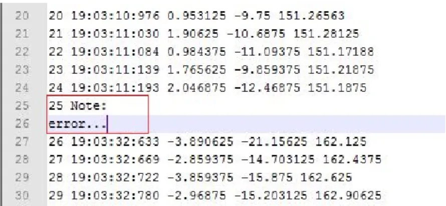
The format of the le that contains the observed data by this application is shown in Figure 4.4. The name of this le is composed by the date and time when the observation ended so we can have an idea of when the observation was made without having to open the le.
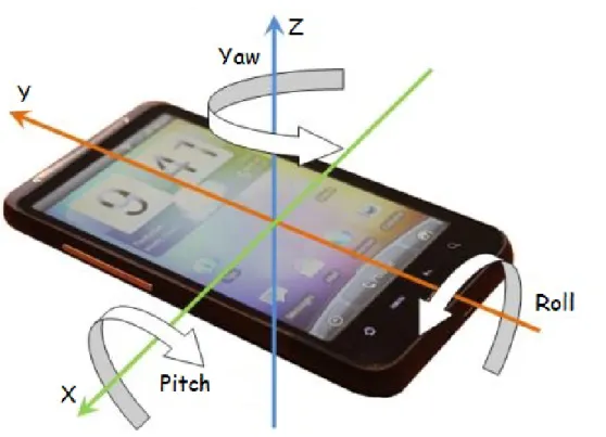
The classes Sensor.TYPE_ORIENTATION and SensorEvent of the Android SDK were to create the onSensorChanged(SensorEvent event) function which is shown in Figure 4.5. All values of Pitch, Roll and Yaw angles are in degrees.
• values[0]: Yaw or Azimuth, angle between the magnetic north direction and the y-axis, around the z-axis (0 to 359). 0=North, 90=East, 180=South, 270=West
• values[1]: Pitch, rotation around x-axis (-180 to 180), with positive values when the z-axis moves toward the y-axis.
• values[2]: Roll, rotation around the y-axis (-90 to 90) increasing as the device moves clockwise.
The collected data is stored in ArrayList of strings [55]. The instructions that are underlined in blue show the values of the Euler angles in the real time application. The instructions underlined in red represents the format in which data is stored in the text le (Time, Pitch, Roll, Yaw).
4.3 Equipment Used in Data Acquisition and Data Processing
In the data collection process, a Topcon HiperPro receiver was used. Although, our system is basically independent of the GNSS equipment used, this model has the necessary requirements: it is a multi-function, multi-purpose double-frequency GPS and Glonass receiver [41]. In the tests performed, it was used baselines up to 20km, which is in accordance with the values used for centimeter-level topographic surveys.
The antenna attitude angles are obtained using an Android Tablet/Smartphone. The Tablet/S-martphone has an orientation sensor and together with the devices accelerometer improves motion sensing accuracy and allows to measure in which direction the device is moving/rotat-ing in space (Pitch, Roll and Yaw), how much and how fast.
Figure 4.6: Tablet Reference Frame
The precision of the orientation and accelerometer sensors is much greater than the precision of the Tablet's/Smartphone's compass and GNSS sensors. The compass and GNSS sensors are used to determine where the device is on the globe, and the orientation and accelerometer are good for nding out where the device has moved in the last few milliseconds. Therefore it depends upon what you're trying to control with the device's movement [56]. However, the measured angles and accelerations tend to drift with time, reason why they are not useful to obtain absolute positions.
It is necessary to use reference stations in order to obtain the coordinates of the observed points in the same coordinate system, even when they are observed at different times. In the tests carried out, two stations were used:
Figure 4.7: TBC Mini-Output File - Coordinates Points
Figure 4.8: TBC Mini-Output File - Time of each Point
Figure 4.7 shows the output le of the TBC. Figure 4.8 shows the second output le of the TBC where it is possible to see where it is stored the time at each point was observed.
4.4 Scripts to Convert Coordinates
In the data acquisition process, it is necessary to know the antenna position with respect to the local coordinate system in order that it will be possible to transform the estimated position using GNSS (bottom of antenna) to the position of interest (position of the ground below the antenna mast).
Two scripts were developed in the C programming language. One to make the conversion from ECEF coordinates which is a Cartesian reference frame with its origin at the centre of the Earth, to local coordinates East-North-Up that are planimetric local coordinates, and the
second to do the inverse conversion. This conversion is necessary because, in order to perform the coordinate corrections, the collected coordinates must be in the same reference frame as the Tablet (East, North, Up), because it uses its compass to point towards the north and the tilt meters use gravity to know what the vertical direction is.
4.4.1 Convert ECEF to ENU Coordinates
This script receives as parameters the names of input/output les and also the height of the antenna mast and it's distance to the ground. This coordinate transformation is based on ellipsoidal coordinates φ, λ, h and the corresponding rectangular coordinates x, y, z. The representation of this ellipsoid in terms of ellipsoidal coordinates is given by:
Figure 4.9: Ellipsoidal and Rectangular Coordinates
The origin of the rectangular coordinate system is the center of the ellipsoid, and the z-axis is its axis of rotation; the x-axis has the Greenwich longitude 0oand the y-axis has the longitude
90o east of Greenwich (i.e., λ = +90o) [59]. The transformation is based on mathematical
formulas of Figure 4.10.
the height of the mast for later do the inverse conversion.
4.4.2 Convert ENU to ECEF Coordinates
The script of this coordinate conversion receives as parameters the names of input/output les and also, the le with saved parameters on conversion ECEF to ENU. This conversion is done based on the ECEF coordinates of the rst point recorded in the parameters le of the previous conversion and then apply the rotation matrix shown in Figure 4.12.
Figure 4.12: Rotation Matrix to X, Y, Z
The script returns as output, a le with the coordinates X, Y, Z. This output le will then be used to construct surfaces of the collected data.
4.5 Air2Ground
When the data is collected, it is very dif cult to guarantee the vertically of the mast, be-cause the antenna attitude will be in uenced by the terrain topography, and consequently the surveyed points will not be at the vertical position of the ground position.
To correct the acquired data, it will be necessary to know the antenna attitude relative to a local reference frame. In order to make simple the conversion, we use the local horizontal plane (E, N) plus the vertical axis (V). This attitude can be described by three rotation angles known by Euler angles (Ω, φ, k or Roll, Pitch and Yaw(Azimuth)) relative to a X, Y, Z reference frame (see Figure 4.14). With this three angles, it is possible to correct each observed point using a simple rotation matrix described in Figure 4.15.
Figure 4.14: Rotation Around Axes X Y Z
Figure 4.15: Rotation Matrix
Air2Ground is the application developed to transform the coordinates of the points processed by TBC from the base of the antenna to the ground. It was implemented in console mode in C# [38] using the IDE Microsoft Visual Studio 2012 [39].
The Air2Ground needs the following parameters: • The time offset
This parameter corresponds to the average of time difference between GPS time and the Tablet/Smartphone time in milliseconds. To get this measure, the free android application "GPS Time" was used where the time difference at the beginning and at the end of the observation is collected, depending on the total time of observation. After some tests with this application it was possible to notice that the differences were not very pronounced. A test was performed for one hour and it was registered the time differences every 10 minutes. And, as it can be seen in Table 4.1, the variation was at maximum 1 second.
Table 4.1: GPS Time Application Test.
• The height of the mast, normally 2.000 m. • The mast distance to the ground
This parameter is measured in the beginning of the survey. • Pitch Tablet/Smartphone sensor error.
• Roll Tablet/Smartphone sensor error. • Three les .txt
One with the coordinates processed in TBC converted to ENU, another with the hour of each GNSS point exported from TBC and nally the le with the data of Android application "GyroData".
To treat the information contained in the input parameters and get the corrected coordinates, the following methods were used:
• GPSFileFormat(string le, string le2)
This method receives as parameters a le with the coordinates of GNSS points and another le with the hours of GNSS points. Here, the assignment is made of hours in each GNSS point collected by the correspondent their "ID". Returns a List [38] with all the correct information from GNSS points (ID, Time, East, North, UP).
• TabletFileFormat(string le, double offset, double offsetP, double offsetR)
This method processes data coming from the Android application "GyroData" which con-tains the observed Euler angles. Receives as parameters, the le with the Euler angles, the time offset, the pitch Tablet/Smartphone sensor error and the roll Tablet/Smartphone sensor error. Here the offsets are added or subtracted to data collected so that the corre-spondence between each instant and each GNSS point is the most accurate possible. This method returns one List [38] with the Euler angles corrected (ID, Time, Pitch, Roll, Yaw) and ready to be assigned to GNSS points.
• TabletGPSFileFormat(List<string> Tablet, List<string> GPS)
This is one of the most important methods of this application. It is here that the synchro-nization is done between GNSS points and Euler angles data set. It receives as parameters the output lists of the two previous methods.
Figure 4.17: Important print of the TabletGPSFileFormat Method
Synchronization begins to be done by comparing the second of time of the GNSS point with the second of time of each Euler angles data set. So, if they are equal, the Pitch,
Figure 4.18: Interpolation Example
The procedure is, for each GNSS point, choose the two angles data sets that are nearest, one before and one after. The difference, in seconds, between these two nearest points is calculated (Diftg), as well as the difference in the observed angles (Px). Then, knowing the difference, in seconds, between the GNSS point and the previous angle data set, using a simple rule of three, it is simple to calculate the correction to be made in the attitude angle.
This process is repeated for each observed GNSS point, thus giving them the correspon-dent correct Euler Angle data set. This method has as output a List constituted by an id, the Euler angles and the corresponding GNSS coordinates (ID, Pitch, Roll, Yaw, East, North, Up) [38].
When the synchronization of the GNSS data with the data from the Android application "GyroData" is done, everything is ready to perform the coordinate corrections using the rotation matrix described before in Section 4.5.
• MatrixTransformation(double pitch, double roll, double yaw, double e, double n, double
u, double h, System.IO.StreamWriter le2)
In this method, the correction of the coordinates of the GNSS points observed is done using a rotation matrix shown in Figure 4.15. Therefore, this method receives as parame-ters the "Pitch" and "Roll", "Yaw", "East", "North", "Up" resulting from the previous method,
the "h" which is the sum of the height of the mast with the mast distance to the ground and the le " le2" which is where GNSS points with the corrected coordinates are stored. Finally, the output of this application are two les, one with "ID, Pitch, Roll, Yaw, East, North, Up" ie, with Euler angles attributed to the GNSS points after the synchronization and another with the result of the coordinates corrections after applying the rotation matrix.
4.6 Surface Computations
With the corrected positions, we will be able to generate a three-dimensional surface. Were developed scripts based on GMT(Generic Mapping Tools) programs[15], to generate the surfaces from the set of point positions observed with the system. The developed scripts are:
• txt2grd: This script starts by receiving data from GNSS observations, thus determining the limits of surfaces. It de nes the limits of the area of interest - the user can be interested in only a sub-area where no extrapolation is done. After using surface (GMT applications), it creates a regular grid from the irregular set of observed points.
• create_surf: This script calculate the differences between interest area and internal sur-faces, the statistics between all of points, interest area and internal surfaces and were calculated statistics between surveys for different all of points, interest area and internal surfaces. Then, it is possible to check the error and the distance between each GNSS point of the surfaces.
• surf_all: Builds the surface of each GNSS observation and a surface with all surfaces built before. To verify in what kind of terrain the GNSS observations were made. The height values are represented by a gray scale.
• surf_diff: Here are buitl the surfaces between the differences calculated in the scrip "create_surf" and the surfaces of each of the GNSS observation. It is possible to verify the error of GPS through a colourful range of -10,10 cm and the changes of the surfaces after apply interpolation techniques.
Finally, repeating the process at different times it will be possible to analyze morphological changes in the monitorized surface during a time frame.
Chapter 5
Tests and Results
Some tests were carried out in order to evaluate the robustness of the system to compute the three-dimensional positions. During these tests it was possible to verify a very important factor, which is the sensitivity and stability of the used Tablet/Smartphone. Two tests were performed using two different Smartphones in the same place, where one (Smartphone 1) was more unstable and sensitive to shaking due to terrain variations than the other (Smartphone 2). The next set of two tests were conducted in an asphalt terrain located about 5.6 km from the base station and had the duration of 5 minutes. Figure 5.1 represents the results after the correction of the coordinates with Euler angles collected by Smartphone 1 and Figure 5.2 represents the results of data collected in the same location using Smartphone 2. The red track is the track with the corrected coordinates and the lilac track has no corrections. The surveys were made in a at terrain then the corrections should be minimal (2/3 centimetres) but, as can be seen in Figure 5.1 there are differences of about 72 cm. The conclusion is that is necessary to test the quality of the Tablet/Smarthphone sensors to be used with our system. Unstable sensors can introduce signi cant errors instead of correcting the tilts.
Figure 5.2: Surface with Smartphone 2 (x and y-axis are the east and north in meters).
Based on data of the previous surfaces, two more surfaces were created that are represented in Figures 5.3 and 5.4. In the two gures, the red track is the track with the corrected co-ordinates and the lilac track has no corrections. In Figure 5.3 it is possible to verify that the distances values between the two surfaces are between 72 cm and -0.5 cm, with media in 6.7 cm. In Figure 5.4 the distances values between the two surfaces are between -2.5 cm and 1 cm, with the average at 0.3 cm which is an good result.
Figure 5.3: Differences between Surfaces of Smartphone 1 (x and y-axis are the east and north in meters).
Another test done was to investigate the in uence of the Pitch and Roll errors in the cor-rection of the coordinates. To do that we rst perform a survey on a at terrain and assume
Figure 5.4: Differences between Surfaces of Smartphone 2 (x and y-axis are the east and north in meters).
that the Tablet/Smartphone has no errors in the Pitch and Roll angles. Then two surfaces were created, one without corrections and another after the corrections. The differences between this two surfaces are calculated (see Table 5.1 line 0). After this we gradually increase the values of the Pitch and the Roll by adding values between -5 and 5 degrees (e.g. if Roll = 15o,
Pitch = 10oand the error is 2o we assume the Roll = 17oand Pitch = 12o) and we calculate new
surfaces and differences for each new set of angles.
Table 5.1 presents the results of the tests described above. It is possible to see that the differences are not signi cant and the maximum differences occur when the error is 5o, however
comparing with the value obtained when we assume there are no errors, this difference is only 3.5 cm.
Figure 5.5: Tested Area with 2 tracks at different colors (x and y-axis are the east and north in meters).
In the Figure 5.6, the red track is the track with the corrected coordinates and the of lilac track has no corrections. This gure shows the differences between the points in the two tracks that are within 4 cm of distance from each other. In these marked points, we can see that the biggest differences are between 1 and 5 cm, but most of the results are between 0 and 1 cm. It is important to stress that are absolute differences between two acquired points at different epochs and by different operators, providing us with an estimate of the uncertainty that we can obtain on the surveys.
Figure 5.6: Differences between points within 4 cm of distance of each other in two different tracks (x and y-axis are the east and north in meters).
Figure 5.7 present an evaluation of the precision that it is possible to obtain inside of the interpolated area. We have computed the mean surface and Figure 5.7 presents the difference between this averaged surface and the corrected coordinates track. With the exception of a very small part, all differences are below 1 cm.
Figure 5.7: Difference between one surface and the average surface (x and y-axis are the east and north in meters).
Figure 5.8: Beach Area with 2 tracks at different colors (x and y-axis are the east and north in meters).
In the Figure 5.9, the red track is the track with the corrected coordinates and the of lilac track has no corrections. This gure shows the differences between the points in the two tracks that are within 10 cm of distance from each other. In these marked points, we can see that the biggest differences are between 5 and 10 cm, but most of the results are between 1 and 5 cm and between 0 and 1 cm.
Figure 5.9: Differences between points within 4 cm of distance of each other in two different tracks (x and y-axis are the east and north in meters).
Figure 5.10 present an evaluation of the precision that it is possible to obtain inside of the interpolated area. We have computed the mean surface and Figure 5.10 presents the difference between this averaged surface and the corrected coordinates track. All differences are between 0 and 1 cm and between 1 and 5 cm.
Figure 5.10: Difference between one surface and the average surface (x and y-axis are the east and north in meters).
Chapter 6
Conclusions and Future Work
6.1 Conclusions
The main objective of this project being developed at SEGAL, in the framework of the SingSubs (collaboration with the National University of Singapore), is to develop integrated methods (software and hardware) for data acquisition (three-dimensional surfaces) in order to perform morphological analysis in sandy shore environments.
The comparison of three-dimensional surfaces acquired at different epochs permit to quantify erosion (or accumulation) rates, and consequently, to identify speci c areas prone to suffer from catastrophic events in the future.
The particular work carried out in the framework of this thesis proposal has two main de ned objectives:
• To develop an hardware device able to position large quantities of discrete points using GNSS data;
• To develop applications able to estimate the three-dimensional surfaces from the col-lected GNSS data.
Such objectives were established after the de nition of the necessary criteria and constraints of the system that was necessary to follow:
• The device should be light and be able to move ef ciently on the beach: no motorization was allowed due to practical or of cial restrictions;
• It should be constructed by integrating cheap components, in particular the attitude ac-quisition device that could be based on current normal Tablets/Smartphones instead of very expensive gyroscopes devices;
• The data should be obtained quickly, using kinematic approaches - the quality of the computation of the three-dimensional surface should be guaranteed by the number of acquired points in order to obtain accurate surfaces.
Although other systems to monitor such environments have been developed in the recent years like Terrestrial and Airborne LiDAR, Total Station surveying, all of them suffer of the several issues, as detailed in Chapter 1 and Chapter 2, that do not comply with the established criteria for our system.
is running easily. In addition, it is currently the most used platform in the world and it does not have associated costs to develop applications. The existing knowledge about development in Java also helped to select this platform.
• Air2Ground - developed in C#, it permits to transform the coordinates of the estimated points using the GNSS processing software from the base of the antenna to the ground using a rotation matrix. The reason to use C# was because it permits to develop robust applications in a very used Integrated Development Environment that was already known. These two applications are also one of the essential components of the system developed in the framework of this work.
In addition, and in order to test the robustness of the developed system, several scripts based on GMT were also created. These scripts permit to generate the three-dimensional surfaces from the set of point positions observed with the system. The scripts are available in the annex. The existing time constraints to nish this component of the entire project did not permit to carry out all desired intensive tests, particularly in what concerns the sensitivity to temporal variation of the observed three-dimensional surfaces. In any case, several tests were already performed that permitted to conclude that the system is already functional and able to perform an accurate monitoring of the morphological evolution of a surface. The tests done that were analysed in this thesis were:
• To test the sensitivity and stability of the used Tablet/Smartphone;
• To investigate the in uence of the Pitch and Roll errors in the correction of the coordi-nates.
• To compare the differences between two individual tracks. For this goal, the data was acquired in rough conditions: a steep asphalt terrain.
• To evaluate the performance of the Acquisition Data Device in a sandy beach environment by comparing the differences between two individual tracks.
The conclusions of these tests were signi cant:
• The stability of the acquisition of the attitude angles differ signi cantly between Tablet/S-martphones. It is fundamental to select a device that provides reliable and stable angles otherwise it introduces signi cant errors on the nal coordinates.
![Figure 1.1: Comparison of beach erosion and re-nourishment [2]](https://thumb-eu.123doks.com/thumbv2/123dok_br/18065902.864088/21.892.151.787.105.390/figure-comparison-beach-erosion-nourishment.webp)