Article
The Oxidation of Formaldehyde on High Overvoltage DSA Type Electrodes
Artur J. Motheoa*, Ernesto R. Gonzaleza, Germano Tremiliosi-Filhoa, Paulo Olivib, Adalgisa R. de Andradeb, Boniface Kokohc, Jean-Michel Légerc, El Mustapha Belgsirc, Claude Lamyc
a
Instituto de Química de São Carlos, Universidade de São Paulo, CP 780, 13560-970, São Carlos - SP, Brazil
b
Departamento de Química, Faculdade de Filosofia, Ciências e Letras de Ribeirão Preto, Universidade de São Paulo, 14040-901, Ribeirão Preto - SP, Brazil
c
Université de Poitiers, Equipe Electrocatalyse, UMR 6503, 40, avenue du Recteur Pineau, 86022 Poitiers - France
Neste trabalho a oxidação eletroquímica do formaldeído é estudada sobre eletrodos dimensionalmente estáveis preparados por decomposição térmica de percursores (correspondentes cloretos). Foram utilizados como eletrodos de trabalho: Ti/Ir0.3Ti0.7O2, Ti/Ru0.3Ti0.7O2 e Ti/ Ir0.2Ru0.2Ti0.6O2. As eletrólises foram realizadas galvanostaticamente em uma célula do tipo filtro prensa em soluções 0,5 mol L-1 H
2SO4 com concentração inicial de formaldeído de 100 mmol L-1. A concentração de formaldeído decresce rapidamente com o tempo de eletrólise sendo que o eletrodo ternário (Ir + Ru + Ti) é o que apresenta maior atividade catalítica. O ânodo contendo somente Ir, apesar de maior carga superficial é o de menor atividade eletrocatalítica. Para a oxidação de ácido fórmico, formado pela oxidação de formaldeído, a presença de Ir na composição do ânodo não favorece o processo, sendo o ânodo contendo somente Ru o mais efetivo para este processo.
The electrochemical oxidation of formaldehyde is studied on dimensionally stable anodes prepared by thermal decomposition of precursors (the corresponding chlorides). The working electrodes used were: Ti/Ir0.3Ti0.7O2, Ti/Ru0.3Ti0.7O2 and Ti/Ir0.2Ru0.2Ti0.6O2. The electrolyses were performed galvanostatically in a filter press cell with 0.5 mol L-1 H
2SO4 solutions with initial formaldehyde concentration equal to 100 mmol L-1. The concentration of formaldehyde decreases fast with the electrolysis time, with the ternary anode (Ir + Ru + Ti) presenting the best performance for this step. The anode containing only Ir, despite presenting the higher superficial charge, is the one with the lowest electrocatalytic activity. For the formic acid oxidation step, the presence of iridium in the anode composition does not promote the process, the anode containing only ruthenium being the most effective for this step.
Keywords: formaldehyde, electrooxidation, DSA, oxides
Introduction
Around the world there is an increasing preoccupation with the cleanness of the environment. Wastewater, coming mainly from industrial effluents, is full of inorganic and/or organic contaminants which have to be treated in order to be considered harmless. In the case of organic substances, one of the possible treatments is electrochemical oxidation lead-ing to, whenever possible, a total “combustion” process which will produce carbon dioxide as the only product. The effec-tiveness of this kind of treatment depends on many variables,
such as for example, the pH of the medium, the current den-sity level and the nature of the electrode material.
Dimensionally stable anode (DSA) type electrodes have been used for many years as stable anodes in the chlor-alkali industry1. These electrodes were generally based on RuO2/
TiO2 mixtures deposited on a metallic substrate (usually tita-nium). Later, modified DSA type electrodes incorporating iri-dium oxides were investigated for the oxygen evolution reac-tion2,3 and also with other metals4-6, in order to modulate their
properties and to increase their service life. More recently, DSA type electrodes have been used for the oxidation of some or-ganic molecules that constitute water pollutants, notable phenols7, as well as for the electrolysis of sea water8,9.
As pointed out in many publications, an indirect electro-chemical oxidation may take place via surface mediators at
Presented at the XI Simpósio Brasileiro de Eletroquímica e Eletroanalítica, Maragogi - AL, Brazil, April 5-9, 1999. Guest editor: Luis Alberto Avaca.
metal oxide electrodes10,11. For this case, Comninellis and
co-workers12 developed a theoretical model to describe, in
a quantitative way, the efficiency of the oxidation reaction that takes place together with oxygen evolution at oxide electrodes. The analysis performed by the authors is spe-cific for oxide electrodes for which the potential of the sur-face redox couple is higher than the thermodynamic poten-tial for oxygen evolution. Oxide electrodes are very inter-esting because proper selection of the material allows a good degree of selectivity. Also, the combination of more than one metal oxide is known to show synergistic effects toward electron transfer reactions.
Presently, there is much interest in studying the oxida-tion of small organic molecules that can be considered as model molecules and, at the same time, are connected to interesting environmental problems. Formaldehyde is one of these molecules that is present in many technological processes such as in the textile industry, and which is nor-mally discarded without previous treatment. The oxidation of formaldehyde on fuel cell type electrodes13 and even on
single crystals14 has been the object of recent
publica-tions. So, it may be of interest to see if formaldehyde can be oxidized at DSA type electrodes.
In this work, the oxidation of formaldehyde is studied on three different DSA type oxide electrodes, in order to determine the effect of the electrode composition and also to verify the possibility of synergistic effects with the in-corporation of different oxides in the electrode.
Experimental
Three different oxide electrodes were used for the elec-trolysis: Ti/Ir0.3Ti0.7O2, Ti/Ru0.3Ti0.7O2 and Ti/
Ir0.2Ru0.2Ti0.6O2. The titanium supported (14 cm2 plates)
oxide layers were prepared by thermal decomposition of precursors in isopropylic alcohol and applied by brushing on the metallic support. The solvent was evaporated at low temperature (80 - 90oC) and the dried layer heated at 450oC
for 5 min. in a 5 L min-1 O2 flux in a preheated oven. These
steps were repeated until the desired oxide thickness (2 µm nominal) was reached. An one hour final annealing at the same temperature and O2 flux completed the procedure. This Ti-support pretreatment and the electrode mounting are described elsewhere15,16.
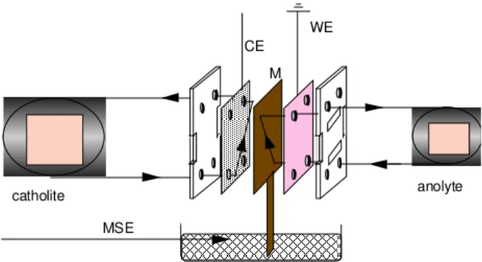
Electrochemical (voltammetry and electrolysis) experi-ments were performed in a filter press cell (flow cell, Electro-cell AB), as shown schematically in Figure 1. The anolyte (100 mmol L-1 solution of formaldehyde in 0.5 mol L-1
H2SO4) and the catholyte (0.5 mol L-1 H2SO4) were
circu-lated separately by a Masterfler peristaltic pump. Two compartments were separated by an ion exchange
membrane (IONAC AM 3470). The galvanostatic electroly-ses were performed using a galvanostat/potentiostat (Wenking Model HP 88). The flat plate DSA electrodes were used as working electrodes and the stainless steel plate as counter electrode. The cyclic voltammograms were obtained by using a Hg/Hg2SO4/SO4-2 (MSE) reference
electrode which was connected, via a sodium sulfate solu-tion, to an extension of the IONAC membrane used to sepa-rate the cell compartments.
CE
MSE
WE
catholite anolyte
M
Figure 1. Scheme of the filter press cell where WE: working
electrode; CE counter electrode; MSE: Hg/Hg2SO4/SO4-2 reference electrode; M: membrane.
Analysis of the reaction products was carried out during the electrolysis by High Performance Liquid Chromato-graphy (HPLC). This apparatus was composed of an isocratic pump (Knauer HPLC Pump 64) and an ion- exchange column (HPX-87H, from Bio-Rad). The eluent was a dilute solution of sulphuric acid (3.33 mmol L-1 H2SO4) at a flow rate of 0.6 cm3
min-1. After separation at room temperature, the electrolysis
products were successively detected with an UV detector (Applied Biosystems 785A) working at λ = 210 nm, and a re-fractometer (Spectra-Physics SP8430). The chromatograms were recorded on a two-channel integrator (D 2500 Merck). The nature of the organic compounds was determined by com-paring their retention times with those for pure reference prod-ucts under the same analysis conditions.
All the solutions were prepared from ultra-pure water (Millipore Milli-Q System) and Merck reagents (formalde-hyde, formic acid, sodium hydroxide and sodium carbon-ate). Before each experiment, the solutions were deaerated with ultra-pure nitrogen (U Quality from L’Air Liquide). All the experiments were performed at room temperature.
Results and Discussion
Cyclic voltammetry
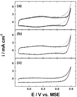
Figure 2 presents the voltammograms of the three differ-ent electrodes in a 0.5mol L-1 H2SO4 solution in the absence
cover-ing mainly the double layer potential region. The behaviour observed is typical of thermally prepared oxide layer elec-trodes2-6 with the surface oxidation potential range
present-ing a displacement to more positive values when in the pres-ence of the organic substance. The broadness of the peaks can be understood in terms of a large heterogeneity in the surface sites, as proposed by Trasatti and Kurzweil 17.
How-ever, by comparison of the three voltammograms, one can see that for the oxides containing iridium in their composi-tions the displacement is bigger. Additionally, the activity of the electrodes, estimated by the voltammogram area follows the order: (Ru + Ti) < (Ir + Ru + Ti) < (Ir + Ti). Both observa-tions are characteristic of the presence of iridium oxide, as shown in the literature18.
can be formed through a reaction of the formaldehyde in acidic medium19. Thus, the experimental observations
described above can be interpreted in terms of the detec-tion of the hydrate form in single aqueous medium while, in acid medium, only one third of the formaldehyde is in the hydrate form and the rest is in the trimeric form.
0 3
6 (a)
0 3
6 (b)
i
/
m
A
c
m
-2
0.0 0.3 0.6 0.9
0 3
6 (c)
E / V vs. MSE
0 2 4 6 8
32 34 98 100 102
C
/
m
m
o
l
L
-1
time/h
Figure 2. Cyclic voltammogram of DSA type electrodes in a 0.5 mol
L-1 H
2SO4 in the absence (dashed line) and presence (full line) of 0.1 mol L-1 formaldehyde. (a) Ti/Ir0.3Ti0.7O2; (b) Ti/Ru0.2Ir0.2Ti0.6O2; (c) Ti/Ru0.3Ti0.7O2. v = 50 mV s-1.
Formaldehyde behavior in acidic medium
In order to determine the formaldehyde concentration as a function of the electrolysis time, it was used the HPLC technique with a refraction index detector. To establish the standards for the chromatograms two solutions were used: 100 mmol L-1 of formaldehyde in water and 100 mmol L-1 of
formaldehyde in 0.5 mol L-1 H
2SO4 aqueous solution. As
illustrated in Figure 3, in acidic medium the detected formal-dehyde concentration is approximately 30% of the concen-tration detected when it is dissolved in pure water. This discrepancy is related to the different forms in which form-aldehyde is present in the solution. In a pure aqueous solu-tion, up to 99% of formaldehyde is present as the hydrate (HCHO. H2O). However, a cyclic trimeric form called trioxane
Figure 3. Dependence of formaldehyde concentration detected by
HPLC with time in the following systems: (l) 100 mmol L-1 in water; (u) 100 mmol L1 in 0.5 mol L-1 H2SO4.
Electrolyses
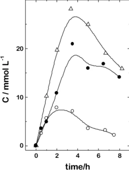
The electrolyses were performed at constant current (40 mA cm-2) and anolyte samples were taken at several
times during the experiment. By the chromatographic re-sults it was possible to observe the concentration varia-tion of formaldehyde, as well as the formavaria-tion of formic acid which was identified as the direct product of formalde-hyde electrooxidation. An example of these results is shown in Figure 4 for the electrolysis of formaldehyde using a Ti / Ir0.3Ti0.7O2 anode. One can see that the concentration of
formaldehyde decreases fast reaching a value below detec-tion in less than 5 h of electrolysis. In the same time period of time the concentration of formic acid increases and reaches a plateau. After four h of electrolysis the concen-tration of formic acid starts decreasing.
In the anodic compartment outlet of the cell a trap con-taining a sodium hydroxide solution was placed in order to determine the CO2 formed in the reaction through the
due to some CO2 lost in the system tubing. However, for all the electrode materials tested, the detectable products in solution were formic acid and carbon dioxide formed through the possible reactions:
Following the same procedure, the curves of formic acid concentration as a function of the electrolysis time, for the different anodes, are shown in Figure 6. In this case, the influence of the anode material is much stronger than in the case of the oxidation of formaldehyde, with the activity varying as: (Ir + Ti) < (Ru + Ir + Ti) < (Ru + Ti).
Figure 4. Dependence of (l) formaldehyde and (m) formic acid
concentration with electrolysis time at 40 mA cm-2 in an aqueous solution of 0.5 mol L- 1 H2S O4 containing 100 mmol L- 1 of formaldehyde and using a Ti/Ru0.3Ti0.7O2 electrode.
HCHO
HCOOH
CO
2H2O -2H+,
-2e--4H+,
-4e--2H+
-2e-H2O
Scheme 1
In order to analyze the influence of the anode composi-tion, the curves of formaldehyde concentration as a func-tion of the electrolysis time, for the different anodes used, are presented in Figure 5. It is possible to observe that the curve corresponding to the ternary oxide anode (Ru + Ir + Ti) is the lowest one, which indicates that the consumption of formaldehyde is faster. On the other hand, the curves corresponding to the binary oxides are almost coincident, being practically impossible to distinguish between their activities. As a first approximation, this difference in the activity between binary and ternary oxides, just for the step involving the disappearance of formaldehyde, can be inter-preted as due to synergistic effects.
0 2 4 6 8
0 10 20 30
C
/
m
m
o
l
L
-1
time/h
Figure 5. Dependence of formaldehyde concentration with
electrolysis time at 40 mA cm-2 from an aqueous solution of 0.5 mol L-1 H2SO4 containing 100 mmol L-1 of formaldehyde and using: (m) Ti/Ru0.3Ti0.7O2; (∆) Ti/Ir0.3Ti0.7O2; (l) Ti/Ru0.2Ir0.2Ti0.6O2.
0 2 4 6 8
0 10 20
C
/
m
m
o
l
L
-1
time/h
Figure 6. Dependence of formic acid concentration with electrolysis
time at 40 mA cm-2 from an aqueous solution of 0.5 mol L-1 H2SO4 containing 100 mmol L-1 of formaldehyde and using: (m) Ti/ Ru0.3Ti0.7O2; (∆) Ti/Ir0.3Ti0.7O2; (l) Ti/Ru0.2Ir0.2Ti0.6O2.
A similar behavior can also be seen in Figure 7, where the increase of the amount of carbon dioxide, in percentage (cal-culated from the mass balance), is shown as a function of the electrolysis time.
From the above observations, it appears that the oxida-tion of formaldehyde to formic acid step (see Scheme 1, reaction 1) is the rds of the total oxidation process on (Ru + Ti) oxide. On the other hand, the rds on (Ir + Ti) and (Ir + Ru
0 2 4 6 8
0 10 20 30
C
/
m
m
o
l
L
-1
+ Ti) oxides seems to be the oxidation of formic acid to carbon dioxide (reaction 2 in Scheme 1). Additionally, there is no experimental evidence for the formation of carbon dioxide directly from formaldehyde, as is represented in Scheme 1 by reaction 3.
The oxidation of formaldehyde on DSA type electrodes only takes place under conditions of simultaneous oxygen evolution, that is, on a surface fully covered by a higher metal oxide20. It is likely that this oxide plays a key role in
the oxidation process. From the results of this work, it is proposed a general mechanism for the oxidation of formal-dehyde with simultaneous oxygen evolution, in acid me-dium, shown in Scheme 2.
Under the experimental conditions imposed to promote the faradaic processes involving formaldehyde oxidation, it is assumed that chemisorptive active sites act as hetero-geneous mediators. Thus, the necessary oxygen transfer is mediated by the higher metal oxides electrogenerated at the surface of the electrode, (MOx)-OH or (MOx)-O. These
models must obviously consider simultaneous oxygen evo-lution as pointed out in steps 1-3 in Scheme 2.
It can be assumed that the electroactive chemisorptive sites can either be decomposed by evolving molecular oxygen, via reaction 3, or intermediate the oxidation of formaldehyde to formic acid, steps 4 and 5, and also inter-mediate the oxidation of formic acid to carbon dioxide, reactions 6 and 7. The nucleophilic attack of the activated sites, (MOx)-O, leads to the O-adsorbed species via the
possible intermediates generated in steps 4 and 6, and in sequence leading to a free formic acid and carbon dioxide,
0 2 4 6 8
20 40 60 80
% C
O2
time/h
Figure 7. Variation of calculated carbon dioxide concentration (in
percentage) with the electrolysis time for the systems using the electrodes: (m) Ti/Ru0.3Ti0.7O2; (∆) Ti/Ir0.3Ti0.7O2; (l) Ti/ Ru0.2Ir0.2Ti0.6O2.
(MOX)-OH
MOX
H2O
H++e
-H++e
-1/2 O2
(MOX)-O
O
C H H
(MOX)
H
H O C O -e
-O C OH
H O C O
-H OH
(MOX) e
-(MOX)-O
e -CO2+H2O
e
-
H H
O C
O C O -H
H (MOX)
H+
CO2+2H++2e
-
Scheme 2.
steps 5 and 7, respectively. The possible direct oxidation of formaldehyde to carbon dioxide involves the hydroxyl species, (MOx)-OH, and can be rationalized through the
reactions 8 and 9. All the above mentioned processes take place simultaneously with competing molecular oxy-gen electrooxy-generation.
Conclusions
The main observations made during this work are as follows:
Prolonged electrolysis permits to identify formic acid, carbon dioxide and molecular oxygen (as a side product) during the oxidation of formaldehyde on DSA type electrodes.
The consumption of formaldehyde is faster on the ternary alloy oxide, (Ir + Ru + Ti), while the binary oxides, (Ru + Ti) and (Ir + Ti), show no difference in activity.
The variation of formic acid concentration with the electrolysis time is much more dependent on the anode material than in the case of the formaldehyde consumption. The activity for the oxidation of formic acid to carbon dioxide varies according to the sequence: (Ru + Ti) > (Ir + Ru + Ti) > (Ir + Ti).
The proposed rds for (Ru + Ti) oxide is the formation of formic acid, while for (Ir + Ti) and (Ir + Ru + Ti) oxides the
rds is carbon dioxide formation.
Acknowledgments
This work was supported by a bilateral exchange pro-gram between the University of São Paulo (USP), Brazil and (COFECUB), France (UC 32/97). A. J. M., E. R. G. and G. T. F. thank FAPESP and CNPq (Brazil).
References
1. de Nora, O. Chem. Ing. Tech. 1970, 42, 222.
2. Rolewicz, J.; Comninellis, Ch.; Plattner, E; Hinden, J.
Electrochim. Acta 1988, 33, 573.
3. Ferrer, J. E.; Victori, L. I. ibid. 1994, 39, 581.
4. Rojas M. I.;Esplandiu, M. J.;Avalle, L. B.; Leiva, E. P. M.; Macagno, V. A. ibid. 1998, 43, 1786.
5. Lassali, T. A. F.; De Castro, S. C.; Boodts, J. F. C. ibid.
1998, 43, 2515.
6. Fóti, G.; Mousty, C.; Reid, V.; Comninellis, Ch. ibid.
1998, 44 , 813.
7. Comninellis, Ch.; Nerini, A. J. Appl. Electrochem.
1995, 25, 23.
8. Belmont, C.; Ferrigno, R.; Leclere, O.; Girault, H. H.
Electrochim. Acta 1998, 44, 597.
9. Ferrigno, R.; Comninellis, Ch.; Reid, V.; Modes, C.; Scannell, R.; Girault, H.H. ibid. 1999, 44, 2871. 10. Lodowicks, E.; Beck, F. Chem. Eng. Technol. 1994, 17, 338. 11. Lyons, M. E. G.; Lyons, C. H.; Michas, A.
J. Electroanal. Chem. 1993, 351, 245.
12. Simond, O.; Schaller, V.; Comninellis, Ch. Electrochim. Acta 1997, 42, 2009.
13. Zhang, X. -G.; Murakami, Y.; Yahikozawa, K.; Takasu, Y. ibid. 1997, 42, 223.
14. Ramanauskas, R.; Jurgaitiene, I.; Vaskelis, A. ibid.
1997, 42, 191.
15. Caravaglia, R.; Mari, C. M.; Trasatti, S. Surf. Technol.
1984, 23, 41C.
16. Angelinetta, C.; Trasatti, S.; Atanasoska, Lj.D.; Atanasosski, R.T. J. Electroanal. Chem. 1986, 214, 535. 17. Trasatti, S.; Kurzweil, P. Platinum Met. Rev. 1994,
38, 46.
18. Kodintsev, I.M.; Trasatti, S.; Rubel, M.; Wieckowski, A.; Kaufher, N. Langmuir 1992, 8, 283.
19. Weissermel, K.; Arpe, H. -J. Industrial Organic Chem-istry, 3rd. Edition, VCH Publishers, Inc., New York, 1997. 20. Foti, G.; Gandini, D.; Comninellis, Ch. Current Topics
in Electrochemistry 1997, 5, 71.
Received: May 31, 1999