FAULT RIDE-THROUGH CAPABILITY OF WIND TURBINE
CONNECTED TO THE GRID IN THE CASE OF UNBALANCED
VOLTAGES
by
Zoran R. IVANOVI], Marko S. VEKI], Stevan U. GRABI], and Ivan M. TODOROVI]
Faculty of Technical Sciences, University of Novi Sad, Novi Sad, Serbia
Original scientific paper DOI:10.2298/TSCI150929033I
This paper deals with control of wind turbine connected to the grid through the back-to-back converter in case of unbalanced grid voltages. The motivation for this research has been found in recent transmission and distribution grid code, which demand modern wind turbines to stay connected to the grid and supply the highest possible apparent power during the grid disturbances. In order to comply with these requirements we proposed improved dual vector current controller to deal with the unbalance imposed by the electrical grid. Controller provides injec-tion of active and reactive power to the grid, even if the voltages are lower than the nominal one. The results are validated using low power prototype and con-temporary hardware-in-the-loop emulation platform. In both cases the controller is based on TMS320F2812 DSP.
Key words: wind turbine, distributed generator, fault ride-through capability, back-to-back converter, hardware-in-the-loop
Introduction
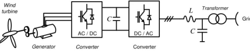
Wind energy systems, photovoltaics and small hydro power-plants are common type of DG units, integrated in the power system. They have a number of positive impacts on the grid such as, lower capital costs due to their smaller size and possibility to contribute to the overall system stability [1-3]. Wind turbine (WT) is one of the most usually employed types of DG units. Almost all WT require controllable power electronics interface [4]. One com-plete WT system is shown in fig. 1. Squirrel cage induction generator is connected through the back-to-back converter, LC filter and transformer to the grid, providing an efficient injec-tion of active and reactive power.
Figure 1. WT unit connected to the grid through the power electronic interface
_______________
Corresponding author; e-mail: zorani@uns.ac.rs
Converter Converter
Grid
L
C
AC / DC DC / AC
Тransformer
C
Wind turbine
In the early stage of the WT technology development there were no requirements, imposed by power companies, demanding WT to stay connected to the grid during the fault, or grid disturbances [5]. The main focus of engineers was protection of WT unit itself. In the last two decades, increasing of DG pene-tration has led to the fast establishment of a variety of grid codes which define WT behaviour in the case of unconventional conditions. Grid code provides minimum operational and security requirements of the WT installations connected to the electric network in order to guarantee supply continuity in the presence of volt-age sags. One of the most commonly used LVRT requirements is created by the German company E.ON Netz. Grid code in other countries usually relies on the German grid code, taking into ac-count specific needs of a certain power system. According to E.ON Netz grid code require-ments in the case of grid faults, the generating plant must stay connected and inject available active and reactive power [7]. These grid code requirements are illustrated in fig. 2. It shows voltage pattern limit of the WT plant based on the induction generator in the point of grid connection.
This paper proposes control algorithm which improves WT behaviour in the case of grid voltage sags. It allows WT to stay connected to the grid and inject active and reactive power, even in the case of severe voltage drops at the connection point. Balanced and unbal-anced voltage sags are considered. Controller is based on the standard DVCC technique and introduces regulation of both, positive and negative sequence components. The main im-provement proposed here has been modification in calculating currents references, which reflects on the amount of active and reactive power injected to the grid.
Tests on WT systems are difficult to perform in a real laboratory due to high power rating of hardware, system complexity, difficulties associated with generation of desired grid voltage profile, and impracticability of disconnecting a WT unit form the rest of the system [8, 9]. The alternatives to the final system testing are either to build a small-scale prototype, which is time consuming, inflexible and expensive, or to use the HIL rapid prototyping simu-lation tools [10]. In this paper both approaches have been combined to achieve comprehensive test results. Firstly, HIL device behaviour was verified in normal operation circumstances by comparison with the real hardware low power test bench, and after that the HIL emulation platform was employed to evaluate the ability of the proposed control algorithm in order to meet pre-defined grid code requirements in balanced and severely unbalanced grid voltage conditions. The entire hardware is emulated in the real–time, using the FPGA platform with a fixed simulation time step of 1 μs. The FPGA based platform interacts with the controller through the custom made I/O board. The control algorithm is implemented using a control platform based on the TMS320F2812 DSP.
Voltage sags
A three phase fault in the power system leads to an equal voltage drop in each phase. Unsymmetrical faults leads to drops in one, two or three phases, with not all phases having
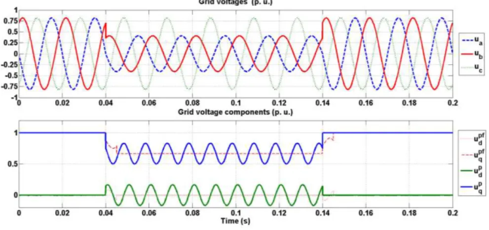
the same attenuation [11]. Unbalanced voltage sags caused by network faults introduce nega-tive sequence grid voltage and current components. The control and operation of a grid-connected VSC under these circumstances have been widely investigated in the literature [12-21]. One example of unbalanced voltage sag is shown in fig. 3. Voltages in two phases drop down to 50% of the nominal one, while third phase remain the same. Disturbance lasts for three periods.
Figure 3. Example of unbalanced voltage sag
In order to calculate balanced voltage sag amplitude in the radial distribution net-works, the schematic shown in fig. 4 has been used. The ZS represents the source impedance, while ZF represents impedance between connection point and fault location.
Figure 4. Balanced voltage sag calculation
Remained voltage at the connection point could be calculated:
E Z Z
Z V
F S
F
sag (1)
the solid line. Voltage sags A, B, and E do not introduce phase shift, while voltage sags F, C, D, and G introduce both, phase and amplitude change.
Figure 5. Voltage sags types – ABC classification
Voltage sags A-D are caused by one-phase, two-phase or three-phase fault, while voltage sags E-G are consequence of two-phase to ground fault. If there is any transformer in the system, like in fig. 6 it can lead to changing of voltage types at the converter terminals from one to other [11].
Figure 6. DG unit connected to the grid
Regardless winding connection of the transformer, voltage sag classification men-tioned in fig. 5 include all possible cases and explain the propagation of three-phase unbal-anced sags from one voltage level to another [11].
System description under unbalanced grid voltages
Unbalanced system voltages and currents can be represented by its positive and negative sequence equivalents. A fast and precise detection of positive and negative sequence voltage angle and magnitude during the transient faults in the grid is an important issue. An unbalanced system of the three phase-voltages (ua ,ub , uc ,) could be represented with its posi-tive (udpq = udp + juqp) and negative sequence (udnq = udn + juqn) components, as given by:
n dq t j p dq t
j
u
e
u
e
u
(2)grid-frequency. In the same manner, unbalanced grid currents also appear and they could be repre-sented in terms of positive and negative sequence current components, similarly to eq. (2):
n dq t j p dq t
j i e i
e
i (3)
where idpq = idp + jiqp and idnq = idn + jiqn.
One case of unbalanced grid-voltage in the original and synchronously rotating ref-erence frame (type C) is shown in fig. 7. It should be noted that in the positive sequence refer-ence frame, a positive component appears as DC, whereas a negative component oscillates at twice the grid frequency. In negative reference frame it is opposite, which is explained thor-oughly in [12]. After filtrating oscillating components DC values for positive and negative sequences (ud f q, ud
f
p) are obtained.
Figure 7. Unbalanced grid voltage representation
The representation of a two-level VSC, used as an actuator in DG application, could be described by differential eq. (4) in the stationary reference frame:
Ri
dt di L u
v (4)
whereR is the grid resistance, and
L
– the grid inductance and
2 /3 2 /3
3
2
c j
j b
a ve ve
v
v (5)
2 /3 2 /3
3
2
c j
j b
a ie ie
i
i (6)
where ναβ and iαβ denote converter pole voltages and line currents, respectively.
Equation (4) can now be transformed and decomposed into two parts in the positive and negative synchronous rotating reference frames, respectively, as shown in eqs. (7) and (8) [12]:
p dq p dq p
dq p dq p
dq Ri j Li u
dt di L
n dq n dq n dq n dq n
dq Ri j Li u
dt di L
v (8)
With regards to this, instantaneous apparent power could be expressed:
)
(
)
(
t
jq
t
p
i
u
s
(9)where active power p(t) and reactive power q(t) are:
) (2 sin )
(2
cos t P t
P P ) t (
p 0 c2 s2 (10)
) (2 sin )
(2
cos t Q t
Q Q ) t (
q 0 c2 s2 (11)
Terms P0 and Q0 designate the value of the average power, while PC2, PS2, QC2, and QS2 are magnitudes of power oscillations caused by unbalance. Detailed expressions for all six
terms are given in [12]. If eqs. (10) and (11) are written in matrix form, it follows:
n q n d p q p d p q p d n q n d p d p q n d n q n d n q p d p q n q n d p q p d c s i i i i u u u u u u u u u u u u u u u u P P Q P 2 2 0 0 (12)
Control algorithm development
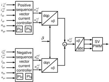
Song and Nam [15] recommended the DVCC to achieve robust operation of a VSC under unbalanced grid-voltage conditions. Its core is regulation of positive and negative se-quence components, allowing transfer of active power to grid at grid frequency, while sup-pressing oscillations at twice grid frequency and maintaining the desired average power fac-tor. A conventional DVCC cannot be implemented under extreme voltage conditions [21]. For severe voltage sags, grid currents could reach unacceptably high values, several times higher than the nominal value. For reliability and converter protection reasons, this should not be per-mitted. Therefore, the modified DVCC with imposed current limitation is proposed here [23].
Current references in the case of modified DVCC are extracted from the equation:
nref q nref d pref q pref d p q p d n q n d p d p q n d n q n d n q p d p q nref q nref d pref q pref d LIM S C GRID i i i i u u u u u u u u u u u u i i i i I P P Q I 0 0 0 2 2 2 0 2 (13)
First row in the eq. (13) is current limiting condition imposed by the grid side inverter. When solving this matrix equation, current components references are obtained:
D u I i p d LIM pref
d (14)
D u I i p q LIM pref
D u I i
n d LIM nref
d
(16)
D u I i
n q LIM nref
q
(17)
where D = [(udp)2 + (uq p
)2 + ((udn)2 + (uq n
)2]1/2. The power delivered to the grid will be lower due to lower grid voltages and imposed current limitation. The conventional DVCC controller structure is shown in fig. 8. In the case of modified DVCC the only difference is in calcula-tion of current references, according to eqs. (14)-(17).
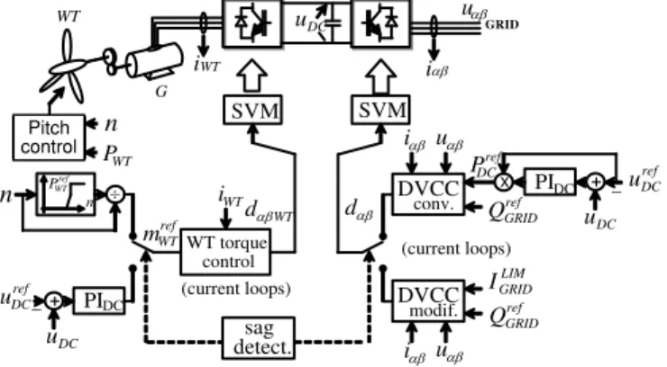
The control block scheme of the whole WT system is repre-sented in fig. 9. The back to back converter which is fed from squir-rel cage induction generator unit is connected to the grid through the LC filter and grid impedance. Transformer is also used between grid and DG unit. Three phase grid currents (iabc) and voltages
(uabc) are measured and
trans-formed to αβ (iαβ uαβ) and dq
do-main (idq udq) using the transfor-mation angle which is obtained by employing PLL estimator. The PLL is designed to estimate accu-rately frequency and phase angle in the case of distorted voltages, including phase jump. More
de-tails can be found in [12] Voltages and currents in dq domain are used to calculate active and reactive power according to eqs. (10)-(11). These expressions are used in order to design dual vector current controller, which is employed in the case of unbalanced voltages.
There are two separate control structures. During the normal system operation WT side inverter is in charge of controlling WT torque (mWT) and speed (n) using vector control
technique, while grid side inverter is in charge of controlling active and reactive power and DC bus voltage. In normal grid conditions torque reference mWTref for WT controller is obtained
based on optimal turbine power characteristic PWTref = f(n) [11]. At the grid side, in normal
conditions conventional DVCC is used (fig. 5.). There, power transfer reference command
PrefDC comes from the output of DC voltage controller and reference average reactive power is
set to Q0 = Qref
GRID = 0. If reactive power different from zero is injected, reference Q0 = Q ref GRID
will be set to the desired value.
After the voltage sag has been detected, control structure has to be altered so that modified DVCC imposes current limit in the output current and WT side converter takes over DC voltage control. Obviously, power flow through the back-to-back converter will be re-duced. Therefore, the WT mechanical input has to be restricted by means of the pitch control. The control structure completes sag detector that manipulates the switching between the two control objectives.
Positive sequence
vector current controller
Negative sequence
vector current controller
dqn dqp
αβ
αβ + ref
dp
i
ref qp
i
qp
i
dp
i
qp
u
dp
u
ref dn
i
ref qn
i
qn i
dn
i
qn u
dn
u
ref dp
u
ref qp
u
ref dn
u
ref qn
u
uref
SV
PWM abc
αβ PId PIq
PId PIq
Control parameters are obtained using symmetrical and module optimum. For prac-tical implementation, the controller is transformed into a time-discrete form using bilinear transformation.
Figure 9. The WT control structure
System performance verification using HIL emulator and experimental set-up
Performance of the proposed control structure is difficult to verify in laboratory for all operating conditions. Difficulties are associated with the lack of high power equipment and impracticability of doing such experiments on live power systems [24-26]. Here, it was de-cided to combine two standard approaches. Firstly, fidelity of HIL emulator was verified us-ing low power hardware setup. After that, HIL platform was configured with the parameter of real 560 kW wind turbine, equipped with induction generator in order to confirm proposed control algorithm for real operating condition.
The HIL verification
In order to verify HIL platform fidelity, experimental setup shown in the fig. 10 is used. Two electrical machines are mechanically coupled, one synchronous machine which is used to set-up wind profile and one induction generator, as a part of wind energy conversion system. Synchronous generator is fed by standard industrial ABB frequency converter, while the wind generator is fed bytailor made back-to-back converter. In this case, dSpacesystem was used as a control card, located inside the PC computer.
Figure 10. Low power hardware prototype
ref WT
P
n
ref DC
u + PIDC
DC
u
n
WT torque control
ref WT
m
(current loops)
WT
d
SVM SVM
ref DC
u
PIDC +
DC
u
x
ref DC
P
DVCC conv. ref
GRID
Q
WT
i
DC
u
i
u
i u
LIM GRID
I
DVCC modif. ref
GRID
Q
i u
(current loops)
d
sag detect. pitch
control
WT
i
n
WT
P
GRID
WT
G
In addition, HIL experiment has been carried out due to show system fidelity. Power stage including power converters and machines is emulated with the universal ultra-low la-tency HIL FPGA-based platform dedicated to power electronics applications. Experimental results are shown in figs. 11-14.
Figure 11. q axis machine current (left – experiment, right – HIL)
Figure 12. d axis machine current (left – experiment, right – HIL)
Figure 13. Wind turbine generator speed (left – experiment, right – HIL)
0.4
0.3
0.2
0.1
0.0
–0.1
0.4
0.3
0.2
0.1
0.0
–0.1
iq
ln
1
iq
ln
1
0.0 0.5 1.0 1.5 0.0 0.5 1.0 1.5 Current reference
Current response
Current reference Current response
Current reference
Current response Current reference Current response
0.0 0.5 1.0 1.5 0.0 0.5 1.0 1.5 1.0
0.5
0.0
–0.5
–1.0
id
ln
1
id
ln
1
1.0
0.5
0.0
–0.5
–1.0
0.1
0.0
–0.1
–0.2
–0.3
–0.4
–0.5
0.1
0.0
–0.1
–0.2
–0.3
–0.4
–0.5
w
_
re
f
ln
1
w_r
e
f
ln
1
0.0 0.5 1.0 1.5 0 1 2
Speed reference Speed response
Figure 14. Grid dq axis currents (up – experiment, down – HIL)
Step response of induction machine currents has been shown. In both cases critical periodical response is obtained, according to control aims. Figure 13 shows induction genera-tor speed response. It can be seen that set reference is achieved in both cases. The HIL and experimental results perfectly match, which means that HIL platform can be used for further algorithm testing.
Verification of DVCC control algorithm using HIL platform
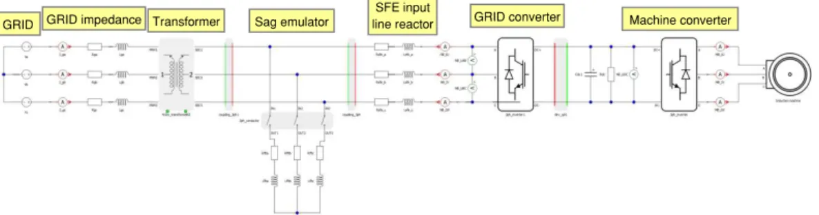
In this section performance of the proposed control principle is verified by using HIL platform. Power stage of the emulated electrical system (fig. 15) is comprised of electri-cal grid, power transformer, voltage sag emulator, grid side converter, machine side converter (back-to-back) and induction generator. It is executed on the FPGA based platform with 1μs latency.
Figure 15. Schematic diagram of WT connected to the grid
–1 0 1 2 3 4 –1 0 1 2 3 4
–1 0 1 2 3 4 –1 0 1 2 3 4 2.0
1.0
0.0
–1.0
–2.0
2
1
0
–1
–2
0.5
0.0
–0.5
–1.0
1.0
0.5
0.0
–0.5
–1.0
iq_
re
f
ln
1
iq_
re
f
ln
1
id_
re
f
ln
1
id
ln1
Current reference Current response
Current reference Current response Current reference
Current response
Current reference Current response
GRID GRID impedance Transformer Sag emulator
SFE input
The VSC is modelled using HIL emulator. They are inherently nonlinear switched circuits where the control of power flow is achieved with precisely timed switching events. The combination of continuous time dynamics (continuous-time state-space) and discrete events (finite automaton) that VSC
exhib-its lends exhib-itself naturally to a hybrid sys-tem modelling approach. Thus, modelling framework was adopted based on GHA with piecewise linear continuous dynamics. The PE circuits (grids side inverter sup-ported by WT) is represented with passive elements (R, L, and C), piece-wise linear switches, a controlled current source and independent voltage sources that yield a piecewise linear state-space representation.
The hardware set-up is shown in fig. 16. On the right side, the HIL emulator box can be seen and on the left side the DSP-based control board. TMS320F2812 DSP controller for control code generation has been used.
Control algorithm is tested for three cases: performance in normal operating condi-tion, behaviour in the case of balanced voltage sag and behaviour in the case of unbalanced voltage sag. Figures 17-21 illustrates behaviour of WT based system in normal voltage condi-tion.
Grid voltages are nominal with the line voltage of 400 V. Parameters of electrical transformer are: 1.5 MVA, 11.4/0.63 kV/kV. These parameters are selected based on real power system data. From fig. 18 it can be seen that grid currents are balanced. There is some ripple due to chosen switching frequency of 2 kHz, but PWM filter cut off most of it. It is similar with the induction generator line currents, shown in fig. 19. Machine electrical torque is quite constant and equals 2500 Nm. The DC bus voltage is also stable, which indicate that the power transfer is correctly managed. In this case generator produces 560 kW of active power, while the reactive power is kept to zero.
Figure 17. Grid voltages – no fault
0 0.01 0.02 0.03 0.04 0.05 0.06 0.07 0.08 0.09 0.1 -600
-400 -200 0 200 400 600
Grid voltages
Time (s)
V
olt
a
g
e
(V
)
Va Vb Vc
Figure 16. The HIL experimental set-up
600
400
200
0
–200
–400
–600
V
o
lta
g
e
[
V
]
0 0.01 0.02 0.03 0.04 0.05 0.06 0.07 0.08 0.09 0.1 Time [s]
Figure 18. Grid currents – no fault
Figure 19. Machine currents – no fault
Figure 20. Machine electrical torque – no fault
0 0.01 0.02 0.03 0.04 0.05 0.06 0.07 0.08 0.09 0.1 -600
-400 -200 0 200 400 600
Grid currents
Time (s)
Curr
e
n
t
(A
)
Ia Ib Ic
0 0.01 0.02 0.03 0.04 0.05 0.06 0.07 0.08 0.09 0.1 -800
-600 -400 -200 0 200 400 600 800
Machine currents
Time (s)
Curr
e
n
t
(A
)
Ia Ib Ic
0 0.01 0.02 0.03 0.04 0.05 0.06 0.07 0.08 0.09 0.1 -3400
-3200 -3000 -2800 -2600 -2400 -2200 -2000
Torque
Time (s)
T
or
q
u
e
(N
m
)
Mel
600
400
200
0
–200
–400
–600
Cur
re
n
t
[
A
]
800
600
400
200
0
–200
–400
–600
–800
0 0.01 0.02 0.03 0.04 0.05 0.06 0.07 0.08 0.09 0.1 Time [s]
0 0.01 0.02 0.03 0.04 0.05 0.06 0.07 0.08 0.09 0.1 Time [s]
Cur
re
n
t
[
A
]
0 0.01 0.02 0.03 0.04 0.05 0.06 0.07 0.08 0.09 0.1 Time [s]
–2000
–2200
–2400
–2600
–2800
–3000
–3200
–3400
T
o
rq
u
e
[
Nm
]
Grid currents
Machine currents
Figure 21. DC bus voltage – no fault
Figures 22-27 show test results in the case of balanced voltage sag (type A). Bal-anced voltage sag is introduced using RL impedance and contactor. With the proper selection of R and L the depth of voltage sag can be chosen.
Figure 22 shows grid voltage sag, type A, with the amplitude attenuation of 49% in regards to nominal voltage. Transient can be seen in the instant of voltage change which is due to RL circuit dynamic. During the voltage sag grid currents are higher than nominal, but they are limited in accordance to the grid side converter control algorithm. A lower grid volt-age and limited grid current imply a decrease in active power flow from the generator to the grid (fig. 24).
Figure 22. Grid voltages – voltage sag type A
Figure 23. Grid currents – voltage sag type A
0 0.01 0.02 0.03 0.04 0.05 0.06 0.07 0.08 0.09 0.1 1028
1030 1032 1034 1036 1038 1040 1042
DC bus voltage
Time (s)
V
olt
a
g
e
(V
)
Vdc
0 0.05 0.1 0.15 0.2 0.25 0.3 0.35 0.4 -1000
-500 0 500 1000
Grid voltages
Time (s)
V
olt
a
g
e
(V
)
Va Vb Vc
0 0.05 0.1 0.15 0.2 0.25 0.3 0.35 0.4 -1000
-800 -600 -400 -200 0 200 400 600 800 1000 1200
Grid currents
Time (s)
Curr
e
n
t
(A
)
Ia Ib Ic
0 0.01 0.02 0.03 0.04 0.05 0.06 0.07 0.08 0.09 0.1 Time [s]
0 0.05 0.1 0.15 0.2 0.25 0.3 0.35 0.4 Time [s]
0 0.05 0.1 0.15 0.2 0.25 0.3 0.35 0.4 Time [s]
DC bus voltage
Grid voltages
Grid currents 1042
1040
1038
1036
1034
1032
1030
1028
1000
500
0
–500
–1000
1200 1000 800 600 400 200 0
–200
–400
–600
–800
–1000
V
o
lta
g
e
[
V
]
V
o
lta
g
e
[
V
]
Cur
re
n
t
[
A
In order to keep power flow balance it is necessary to reduce energy production of distributed generator. This is achieved by proper reduction of machine torque reference. Ac-cording to the lower torque references machine currents will be also reduced (fig. 25). The DC bus voltage is still stable, except during transient, when minor deviation occurs. The DC bus stability is indicator that the power flow is correctly managed.
Figure 24. Active and reactive power – voltage sag type A
Figure 25. Machine currents – voltage sag type A
Figure 26. Electrical torque – voltage sag type A
0 0.05 0.1 0.15 0.2 0.25 0.3 0.35 0.4
0 200 400 600 800 1000 A ct ive p o w e r (kW )
0 0.05 0.1 0.15 0.2 0.25 0.3 0.35 0.4
-40 -20 0 20 40 Time (s) R eac tiv e pow er (k VAr)
0 0.05 0.1 0.15 0.2 0.25 0.3 0.35 0.4 -1000 -800 -600 -400 -200 0 200 400 600 800 Machine currents Time (s) Curr e n t (A ) Ia Ib Ic
0 0.05 0.1 0.15 0.2 0.25 0.3 0.35 0,4 -4000 -3500 -3000 -2500 -2000 -1500 -1000 -500 0 500 Torque Time (s) T or q u e (N m ) Mel
0 0.05 0.1 0.15 0.2 0.25 0.3 0.35 0.4
0 0.05 0.1 0.15 0.2 0.25 0.3 0.35 0.4 Time [s] 1000 800 600 400 200 0 A ctive p o we r [ kW ] 40 20 0 –20 –40 Rea ctiv e p o we r [ kV A r ]
0 0.05 0.1 0.15 0.2 0.25 0.3 0.35 0.4 Time [s] 800 600 400 200 0 –200 –400 –600 –800 –1000 Cur re n t [ A ]
Figure 27. The DC bus voltage – voltage sag type A
The results shown in figs. 28-33 show the response on unbalanced voltage sag type E. Two phases drop to 50 % of nominal voltage, while third one stay the same as before the voltage sag happen. Before the voltage sag active power injected to the grid was 300 kW. During the voltage sags currents are sinusoidal, but unbalanced. Currents are slightly higher than the values before sags. Due to limited currents and lower grid voltages, the power in-jected to grid is lower (fig. 30). This means that production of generator is slightly lower, due to the fact that generator speed is kept constant. The DC bus voltage is stable in this case, which means that our DVCC controller work properly.
Figure 28. Grid voltages – voltage sag type E
Figure 29. Grid currents – voltage sag type E
0 0.05 0.1 0.15 0.2 0.25 0.3 0.35 0.4 980
1000 1020 1040 1060 1080 1100 1120
DC bus voltage
Time (s)
V
olt
a
g
e
(V
)
Vdc
0 0.05 0.1 0.15 0.2 0.25 0.3 0.35 0.4 0.45 0.5
-800 -600 -400 -200 0 200 400 600 800
Grid voltages
Time (s)
V
olt
a
g
e
(V
)
Va Vb Vc
0 0.05 0.1 0.15 0.2 0.25 0.3 0.35 0.4 0.45 0.5 -1000
-800 -600 -400 -200 0 200 400 600 800 1000 1200
Grid currents
Time (s)
Curr
e
n
t
(A
)
Ia Ib Ic
800
600
400
200
0
–200
–400
–600
–800
DC bus voltage
Grid voltages
Grid currents
0 0.05 0.1 0.15 0.2 0.25 0.3 0.35 0.4 0.45 0.5 Time [s]
0 0.05 0.1 0.15 0.2 0.25 0.3 0.35 0.4 0.45 0.5 Time [s]
0 0.05 0.1 0.15 0.2 0.25 0.3 0.35 0.4 Time [s]
1200 1000 800 600 400 200 0
–200
–400
–600
–800
–1000 1120
1100
1080
1060
1040
1020
1000
980
V
o
lta
g
e
[
V
]
V
o
lta
g
e
[
V
]
Cur
re
n
t
[
A
Figure 30. Active and reactive power – voltage sag type E
Figure 31. Machine currents – voltage sag type E
Figure 32. Electrical torque – voltage sag type E
0 0.05 0.1 0.15 0.2 0.25 0.3 0.35 0.4 0.45 0.5
150 200 250 300 350 400 450 A ct ive p o w e r (kW )
0 0.05 0.1 0.15 0.2 0.25 0.3 0.35 0.4 0.45 0.5
-10 -5 0 5 10 time (s) R e a ct ive p o w e r (kV A r)
0 0.05 0.1 0.15 0.2 0.25 0.3 0.35 0.4 0.45 0.5
-800 -600 -400 -200 0 200 400 600 800 Machine currents Time (s) Curr e n t (A ) Ia Ib Ic
0 0.05 0.1 0.15 0.2 0.25 0.3 0.35 0.4 0.45 0.5
-4000 -3000 -2000 -1000 0 1000 2000 Torque Time (s) T or q u e (N m ) Mel
0 0.05 0.1 0.15 0.2 0.25 0.3 0.35 0.4 0.45 0.5 450 400 350 300 250 200 150
0 0.05 0.1 0.15 0.2 0.25 0.3 0.35 0.4 0.45 0.5 Time [s] A ctive p o we r [ kW ] Rea ctiv e p o we r [ kV A r ] 10 5 0 –5 –10 Machine Currents 800 600 400 200 0 –200 –400 –600 –800 Cur re n t [ A ]
0 0.05 0.1 0.15 0.2 0.25 0.3 0.35 0.4 0.45 0.5 Time [s]
Figure 33. The DC bus voltage – voltage sag type E
Conclusion
This paper proposed a novel power flow control strategy for wind turbine systems connected to the grid under unbalanced conditions. Proposed control algorithm enabled dis-tributed generator to stay connected to the grid during disturbances and to inject active and reactive power in accordance with its capability. Algorithm principles are verified using real hardware and hardware-in-the-loop emulation platform.
Acknowledgment
This research was partially co-funded by the Ministry of Education, Science and Technological Development of Republic of Serbia under contract No. III 042004 and by the Provincial Secretariat for Science and Technological Development of AP Vojvodina under contract No. 114-451-3508/2013-04.
Acronyms
DC – direct current DG – distributed generation DVCC – dual vector current control FPGA – field programmable gate area GHA – generalized hybrid automaton HIL – hardware-in-the-loop LVRT – low voltage ride-through
PC – personal computer PE – power electronics PLL – phase locked loop PWM – pulse width modulation VSC – voltage source converter WT – wind turbine
References
[1] Hassan, F., On Power Electronics Interface for Distributed Generation Applications and its Impact on System Reliability to Customers, Technical report, Chalmers University of Technology, Sweden, 2005 [2] Ezzat, M., et al.: Low-Voltage Ride-through Techniques for DFIG-Based Wind Turbines:
State-of-the-art Review and Future Trends, Proceedings, IEEE IECON 2013, Vienna, 2013, pp. 236-242
[3] Yang, Y., Blaabjerg, F., Low-Voltage Ride-Through Capability of a Single-Stage Single-Phase Photo-voltaic System Connected to the Low-Voltage Grid, International Journal of Photoenergy, ID 257487, 2013
[4] Magueed, F., et al.: Design of Robust Interface for Wind Power Applications, Proceedings, Nordic Wind Power Conference, Gothenburg, Sweden, 2004, pp. 1-6
[5] Dumnic, B., et. al., An Improved MRAS Based Sensorless Vector Control Method for Wind Power Generator, Journal of Applied Research and Technology – JART, 10 (2012), 5, pp. 687-697
0 0.05 0.1 0.15 0.2 0.25 0.3 0.35 0.4 0.45 0.5
980 1000 1020 1040 1060 1080 1100 1120
DC bus voltage
Time (s)
V
olt
a
g
e
(V
)
Vdc
DC bus voltage 1120
1100
1080
1060
1040
1020
1000
980
0 0.05 0.1 0.15 0.2 0.25 0.3 0.35 0.4 0.45 0.5 Time [s]
V
o
lta
g
e
[
V
[6] Sinha, R. K., et al., Analyses of Voltage Sags With Different DG for Various Faulty Conditions, Inter-national Journal of Computer Communication and Information System, 12 (2010), 1, pp. 189-193 [7] Ivanović, Z., et al.: Control of Multilevel Converter Driving Variable Speed Wind Turbine in Case of
Grid Disturbances, Proceedings, 12th IEEE EPE-PEMC, Portoroz, Slovenia, 2006, pp. 1569-1573 [8] Saccomando, G., et al., Improving Voltage Disturbances Rejection for Variable-Speed Wind Turbines,
IEEE Trans. Energy Convers., 17 (2002), 3, pp. 422-428
[9] Guo, X., et al., Flexible Control Strategy for Grid-Connected Inverter under Unbalanced Grid Faults Without PLL, IEEE Trans. Power Electron., 30 (2015), 4, pp. 1773-1778
[10] Benigni, A., Monti, A., A Parallel Approach to Real-Time Simulation of Power Electronics System,
IEEE Trans. Power Electron., 30 (2015), 9, pp. 5192-5206
[11] Boolen, M., Voltage Recovery after Unbalanced and Balanced Voltage Dips in Three-Phase Systems,
IEEE Trans. Power Del., 18 (2003), 4, pp. 1376-1381
[12] Ivanović, Z., et al., HIL Evaluation of Power Flow Control Strategies for Energy Storage Connected to Smart Grid under Unbalanced Conditions, IEEE Trans. on Power Electron., 27 (2012), 11, pp. 4699-4710
[13] Noguchi, T., et al., Direct Power Control of PWM Converter without Power-Source Voltage Sensors,
IEEE Trans. Ind. Appl., 34 (1998), 3, pp. 473-479
[14] Bellmunt, O., et al., Ride-Through Control of a Doubly Fed Induction Generator under Unbalanced Voltage Sags, IEEE Trans. Energy Convers., 23 (2008), 4, pp. 1036-1045
[15] Song, H., Nam, K., Dual Current Control Scheme for PWM Converter Under Unbalanced Input Voltage Conditions, IEEE Trans. Ind. Electron., 46 (1999), 5, pp. 953-959
[16] Jiang, W., Different Control Objectives for Grid-Connected Converter under Unbalanced Grid Voltage Using Forgotten Iterative Filter as Phase Lock Loop, IET Power Electronics., 8 (2015), 9, pp. 1798-1807
[17] Guo, X., et al., Asymmetrical Grid Fault Ride-Through Strategy of Three-Phase Grid-Connected In-verter Considering Network Impedance Impact in Low-Voltage Grid, IEEE Trans. Power Electron., 29
(2014), 3, pp. 1064-1068
[18] Wang, F. et al., Pliant Active and Reactive Power Control for Grid Interactive Converters under Unbal-anced Voltage Dips, IEEE Trans. Power Electron., 26 (2011), 5, pp. 1511-1521
[19] Suh, Y., Lipo, T., Control Scheme in Hybrid Synchronous Stationary Reference Frame for PWM AC/DC Converter under Generalized Unbalanced Operating Conditions, IEEE Trans. Ind. Appl., 42
(2006), 3, pp. 825-835
[20] Ng, C., Ran, L., Unbalanced Grid Fault Ride-Through Control for a Wind Turbine Inverter, IEEE Trans. Ind. Appl., 44 (2008), 3, pp. 845-856
[21] Suh, Y., et al., A Comparative Study on Control Algorithm for Active Front-End Rectifier of Large Motor Drives Under Unbalanced Input, IEEE Trans. Ind. Appl., 47 (2011), 3, pp. 1419-1431
[22] Zhang, L., Boolen, M., Characteristic of Voltage Dips (Sags) in Power Systems, IEEE Trans. Power Del., 15 (2000), 2, pp. 827-832
[23] Ivanović, Z., et al.: Wind Turbine Integration into the Smart Grid in Case of Unbalanced Voltage Conditions, Proceedings, The 7th International Conference on Engineering and Technology, ICET-2015, Phuket, Thailand, ICET-2015, pp. 1-4
[24] Čelanović, N., et al., Cyber Physical Systems: A New Approach to Power Electronics Simulation, Con-trol and Testing, Advances in Electrical and Computer Engineering, 1 (2012), Feb., pp. 33-38
[25] Rodriguez-Andina, J. J., et al., Advanced Features and Industrial Applications of FPGAS-a Review,
IEEE Trans. Industrial Informatics, 11 (2015), 4, pp. 853-864
[26] Weaver, W. W., Parker, G. G.,: Real Time Hardware-in-the-Loop Simulation for Optimal DC Microgrid Control Development, Proceedings, IEEE 15th Workshop on Control and Modeling for Power Electron-ics, COMPEL, 2014, pp. 1-6