*e-mail: [email protected]
Presented at the International Symposium on High Temperature Corrosion in Energy Related Systems, Angra dos Reis - RJ, September 2002.
Corrosion Resistance of a Steel Under an Oxidizing Atmosphere
in a Fluid Catalytic Cracking Regenerator
Ieda Caminhaa, Chaoliu Zengb, Marcelo Piza Paesc Maurício Jesus Monteirod, Fernando Rizzod*
aInstituto Nacional de Tecnologia, Laboratório de Metalografia e de Dureza
Av. Venezuela, 82, sala 626, 20081-310 Rio de Janeiro, Brazil
bInstitute of Corrosion and Protection of Metals,State Key Laboratory for Corrosion and
Protection, The Chinese Academy of Science, 110015 Shenyang, China cPETROBRÁS/CENPES/SUPEP/DIPLOT/SEMEC, Cidade Universitária
Quadra 7, Ilha do Fundão, 21949-900 Rio de Janeiro, Brazil
dPontifícia Universidade Católica do Rio de Janeiro,Departamento de Ciências dos
Materiais e Metalurgia, Rua Marquês de São Vicente, 225, 22 453-900 Rio de Janeiro, Brazil
Received: September 2, 2002; Revised: September 4, 2002
In the present work, the corrosion resistance of an ASTM A 387 G11 steel was evaluated under two conditions: an oxidizing atmosphere in a fluid catalytic cracking regenerator of a petro-leum processing unit and a simulated atmosphere in the laboratory, at temperatures of 650 °C and 700 °C. The characterization of the phases present in the oxidized layer was carried out by X-ray diffraction (XRD), optical microscopy (OM) and scanning electron microscopy (SEM) with X-ray energy dispersive analysis (EDS). Severe corrosion was observed after exposure to both the real and simulated conditions, with formation of several iron oxides (Fe2O3, Fe3O4 and FeO) in the
product scale layer, as well as a slight inner oxidation and sulfidation of chromium in the substrate. Internal nitridation of the silicon and the manganese was observed only in the real condition, probably related to the long-term exposure inside the regenerator.
Keywords:corrosion resistance, low alloy steel, oxidant atmosphere, regenerator, petroleum
processing unit
1. Introduction
Corrosion of materials may represent a heavy burden for industry in general, especially for the petroleum indus-try where the oil and gas compositions are responsible for reducing the service life of component materials of equip-ment due to severe corrosion attack and, consequently, to considerable expenses related to the maintenance and re-placement of parts in a processing unit1-4. Production
shut-down of a petroleum-processing unit can result in a loss of up to 80,000 distilled barrels in a single day.
In order to mitigate corrosion problems, two approaches are usually employed: the selection of corrosion resistant materials, which may increase the cost of equipment, or the application of a coating to a cheap but less corrosion resist-ance material. In recent years, several studies have been done in the field of coating protection and development of new
alloys, aiming to minimize or eliminate corrosion on the metallic structure of critical parts. In the petroleum indus-try, thermally sprayed aluminum coatings have been suc-cessfully used for the protection of offshore and marine struc-tures, due to its good corrosion resistance and consequent increase in the service life of metallic parts and equipments5.
In the present study, the corrosion resistance of an ASTM A 387 G11 low alloy steel was evaluated. This steel is widely employed in the manufacture of pressure vessels designed for elevated temperature service. Coupon samples were ex-posed to the oxidizing atmosphere in the regenerator region of a fluid catalytic cracking unit (FCCU) of an oil refinery and to a simulated condition in laboratory.
positions used in such systems.
1. Experimental
Two experimental procedures were used: degradation of specimens in service and degradation of specimens in the laboratory, simulating the real conditions of service. In both cases, the corrosion resistance of an ASTM A 387
“real condition”, the samples were fixed inside the regen-erator of a fluid catalytic cracking unit, more specifically in the stand pipe well and orifice chamber regions, under an oxidant atmosphere provided by the burning of the coke adhered to the catalyst. A schematic of the FCCU and the place where the samples were fixed is shown in Fig. 1.The samples were subjected to a temperature of around 650 °C in the stand pipe well and 700 °C in the orifice chamber regions for two and a half years, which is the usual time of a campaign in a petroleum processing unit.
In the second procedure the service atmosphere was simulated in the laboratory and was designated “simulated condition”. A gas mixture with the composition N2-2%O2 -3%SO2 -10%CO2 (vol%.) was used in order to simulate the atmosphere inside the regenerator. The resulting atmosphere was oxidizing, with the oxygen potential calculated to be 1.42 × 10⁻² atm, the sulfur potential 6.79 × 10⁻³⁴ atm and the
carbon activity virtually zero. In this condition, the samples were hung in a quartz tube inside a vertical furnace that was coupled to a temperature controller (PID). The variation in temperature was smaller than 0.5°. The flux of gas mixture was introduced in the quartz tube minutes before the nace started heating. The sample was placed inside the
fur-Table 1. Nominal composition of ASTM A 387 G11 low alloy steel (wt.%).
%C %Mn %P %S %Si %Cr %Mo
0.05-0.17 0.40-0.65 0.0035 max. 0.0035 max. 0.50-0.80 1.00-1.50 0.45-0.65
Figure 1. Schematic drawing of the FCC unit, indicating the local inside the regenerator where the G11 steel samples were fixed.
nace after the temperature of interest was reached. Sample cooling occurred inside the furnace after it had been turned off. The samples were subjected to a test temperature of 700 °C during 70 h of treatment.
After removing the samples from the regenerator (real condition) and the furnace (simulated condition), cross sec-tions were cut and cold mounted for conventional metallographic preparation. The corroded surfaces were analyzed by X-ray diffraction (XRD), optical microscopy (OM) and scanning electron microscopy (SEM) with X-ray energy dispersive analysis (EDS).
2. Results and Discussion
G11 steel before degradation
The original microstructure of the ASTM A 387 G11 before the corrosion degradation is presented in Fig. 2. It is constituted by ferrite and pearlite, with a fairly homogene-ous grain size.
G11 steel subjected to the real condition
Severe corrosion was observed for both samples exposed to the oxidizing atmosphere inside the regenerator at the temperatures of 650 °C and 700 °C. The formation of sev-eral iron oxides such as Fe2O3, Fe3O4 and FeO, as well as a slight internal oxidation and sulfidation of the chromium and the iron in the substrate near the corroded layer/substrate interface were observed. A significant internal nitridation of the silicon and the manganese was also observed for both
samples.
Figure 3 shows the morphology in cross-section of the G11 steel sample subjected to the real condition inside the regenerator, in the standpipe well region at 650 °C.
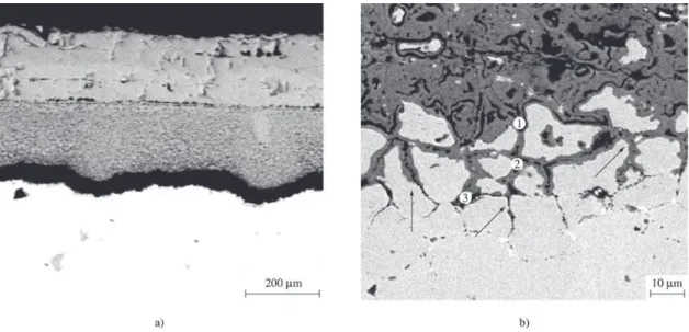
The iron oxides present in the corrosion layer were con-firmed by X-ray diffraction and are in accordance with the Figure 3. SEM cross-section of the G11 steel sample subjected to the real condition at 650°C, with different magnifications. a) General view of the corroded layer and substrate; b) Expanded view of the corroded layer/substrate interface, showing in details the fissure in the corroded layer and the presence of precipitates in the substrate.
extending from the surface to the corroded layer/substrate interface (Fig. 3b), may have formed during the cooling or metallographic preparation. This thickness value is very low if one considers the long time of sample exposure (2 1/2 years). However, the original thickness of the corroded layer might be larger. It is possible that during the campaign time of the processing unit, the corroded layer detached due to
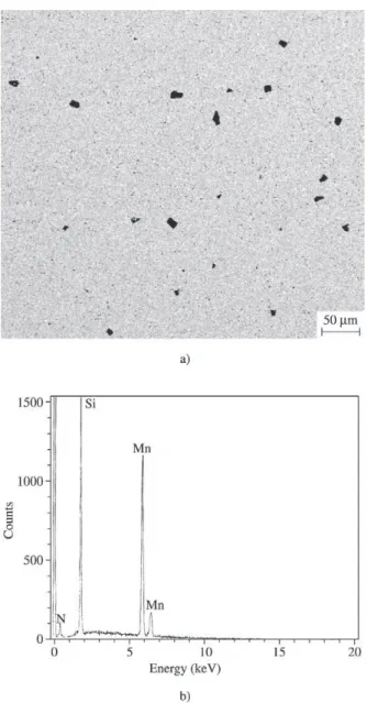
Figure 5. Detail of the internal precipitation of the G11 steel sam-ple at 650 °C in the real condition. a) SEM micrography illustrat-ing the morphology of the precipitates; b) EDS spectrum of the precipitates.
Figure 6. SEM cross-section of the G11 steel sample subjected to the real condition at 650 °C , with different magnifications. a) General view of the sample, showing in detail the fissure in the corroded layer; b) Expanded view, showing the corroded layer/ substrate interface and in detail the internal oxidation and sulfidation of the chromium and the iron.
tion at 650 °C.
chro-mium oxides and sulfides beneath the layer. In those inter-nal regions, the oxygen activity becomes very low while sulfur activity becomes relatively high, leading to the for-mation of chromium and iron sulfides6-11.
Figure 5 shows the internal precipitation found in the G11 steel subjected to the real condition at 650 °C. There was significant internal precipitation (Fig. 5a) throughout the entire substrate. The morphology of the precipitates was irregular both in size and geometry. An EDS spectrum (Fig. 5b) confirmed the presence of nitrogen, silicon and manganese suggesting an internal nitridation of the silicon and the manganese present in the alloy. The long time of exposure in the real service conditions (2.5 years), in which the temperature could reach 1000-1100 °C due to the burn-ing of abnormal amount of coke in the catalyst surface, al-lowed nitrogen diffusion into the alloy and the reaction with less noble metals (Mn, Si), leading to the formation of man-ganese and silicon nitride12-13. In this case, the oxygen
ac-tivity becomes very low (around 10-28 atm) while nitrogen
activity becomes relatively high (around 10-3 atm), leading
to the formation of silicon and manganese nitrides (Si3N4 and Mn4N), according to phase stability diagrams for Si-Mn-O and Si-Mn-N systems14.
The G11 steel sample subjected to the real condition at 700 °C showed a similar corrosion behavior to that at 650 °C. This can be seen in the Fig. 6 and 7. However, the thickness of the corroded layer, approximately 1000 µm, is
compat-ible with the long time of exposure during the campaign of the processing unit (2.5 years).
Significant internal nitridation of the silicon and the manganese was also observed, with the long time of expo-sure in the real condition undoubtedly being responsible for the intense precipitation. The amount of precipitates in the G11 steel subjected to the higher temperature (700 °C) is larger when compared to the sample exposed to the lower temperature (650 °C), indicating the occurrence of higher nucleation rate which is a contradiction with the theory. This apparent contradiction can be explained because the sam-ple subjected to the higher temperature was fixed in the ori-fice chamber region (Fig. 1), where the temperature changes during the abnormal FCCU operation conditions were not so significant when compared to the sample fixed in the stand pipe well region, where the temperature could reach 1000-1100 oC. Another feature that could contribute to
in-crease the amount of internal precipitates is the higher solu-bility of nitrogen in the alloy at 700 °C, 1685.4 ppm vs.
1335.8 ppm at 650 °C.
G11 Steel subjected to the simulated condition
Similar to the G11 steel samples exposed to the real con-dition at 650 °C and 700 °C, severe corrosion as well as a slight internal oxidation and sulfidation of the chromium and the iron near the corroded layer/substrate interface was
observed in the sample subjected to the simulated condi-tion at 700 °C. However, the corroded layer was not homo-geneous when compared to those resulting from the real condition, presenting two distinct layers: the smoother ex-ternal one, constituted predominantly by Fe3O4 and the in-ner layer with great porosity, where the EDS analysis de-tected primarily sulfur and chromium, leading probably to the formation of Cr2S3. The corroded layer was detached from the substrate along their interface.
Figure 8a shows the general view of the corroded layer and substrate. One can observe clearly the presence of two distinct layers and the detachment of the corroded layer from the substrate. In Fig. 8b, the internal oxidation and sulfidation of the substrate are indicated by arrows.
No sign of internal nitridation of the silicon and the manganese was observed in the G11 steel sample subjected to the simulated condition at 700 °C during 70 h. This may be an indication that the internal precipitation is related to the long time of exposure inside the regenerator (2.5 years) in the real service condition.
3. Conclusions
Exposure of the G11 steel samples to both real and simu-lated conditions allowed for easy oxygen and sulfur ingress into the substrate, promoting the formation of a corroded layer containing Fe oxides. The occurrence of internal sulfidation and oxidation next to the corroded layer/substrate interface was also observed.
There was significant internal nitridation of the silicon and the manganese observed in the G11 steel samples sub-jected to the real condition, which is probably related to the long time of exposure inside the regenerator of the fluid catalytic cracking unit.
The oxidizing atmosphere in both the real and simu-lated conditions, allowed for the rather rapid penetration of oxygen, sulfur, and nitrogen into the alloy, leading to inter-nal oxidation, sulfidation, and nitridation of the G11 steel, suggesting that this steel cannot be employed in the atmos-phere studied.
Acknowledgments
The authors thank the Science and Technology Minis-try of Brazil and FINEP for the financial support trough ÔMEGA project and USIMINAS for supplying the steel.
References
1. Charles, J.; Bonnefopis, B.; Dupoiron, F. Materials Sci-ence and Engineering, v. 87, p. 151-159, 1987.
2. May, V.E. Materials Performance, p. 18-22, 1985. 3. Walker, H.B. Hydrocarbon Processing, p. 80-84, 1984. 4. Agarwal, D.C.; Brill, U.; Heubner, U. The NACE Annual
Conference, Paper n. 451 1992.
5. Fischer, K.P.; Thomason, W.H.; Rosbrook, T.; Murali, J.
The NACE Annual Conference, Paper n. 499, 1994. 6. Wood, G.C. Oxidation of Metals, v. 2, n.1, p. 11-56, 1970. 7. Kofstad, P. High Temperature Corrosion, Elsevier
Ap-plied Science, London & New York, 1988.
8. Giggins, C.S.; Petit, F.S. Oxidation of Metals, v. 14, n. 5, p. 363-413, 1980.
9. Young, D.J.; Watson, S. Oxidation of Metals, v. 44, n. 1/ 2, p. 239-263, 1995.
10. Caminha, I.; et all. Materials Science Forum, v. 369-372, p. 655-662, 2001.
11. Rizzo, F.; et all., The NACE Annual Conference, Paper n. 1169, 2001.
12. Besters, D. Diffusion, American Society of Metals, Met-als Park, OH, p. 209-240, 1973.
13. Leslie, W. Physical Metallurgy of Steels, McGraw-Hill, New York, p. 112, 1981.
14. Software HSC OUTOKUMPU.