IEEE SIGNAL PROCESSING LETTERS, VOL. 19, NO. 5, MAY 2012 247
Uni
fi
ed Tensor Modeling for Blind Receivers in
Multiuser Uplink Cooperative Systems
Carlos Alexandre Rolim Fernandes, André Lima Férrer de Almeida
, Member, IEEE
, and
Daniel Benevides da Costa
, Member, IEEE
Abstract—In this letter, we present new blind receivers for
uplink multiuser cooperative diversity systems. Considering amplify-and-forward (AF), fixed decode-and-forward (FDF), and selective decode-and-forward (SDF) relaying protocols, the proposed receivers exploits a unified formulation of the received signal as a CANDECOMP/PARAFAC (CP) model with dimensions . Under the assumption that channel state information (CSI) is not available neither at the relays nor at the base station, the proposed receiver jointly and blindly estimates the transmitted symbols and channel parameters. In addition to avoiding the use of pilots symbols, the CP-based receiver can operate with less base station antennas than users or, alternatively, with a single relay per user.
Index Terms—Blind receiver, CANDECOMP/PARAFAC
de-composition, cooperative diversity, relaying.
I. INTRODUCTION
C
OOPERATIVE diversity has recently emerged as a promising wireless solution due to its ability for ex-ploiting spatial diversity without the need of multiple antennas implemented at the terminals. More specifically, cooperative diversity systems emulate an antenna array in a distributed manner by allowing one or more mobile terminals to relay the information transmitted from a source node to the destination node . Several cooperative relaying protocols have been pro-posed in the literature such as the amplify-and-forward (AF), fixed decode-and-forward (FDF), and selective decode-and-for-ward (SDF) [1]. The AF protocol avoids decoding at the relays and, therefore, is often preferable when complexity and/or latency issues are of importance. The FDF protocol includes decoding at the relay nodes, being an alternative to the AF protocol in noise-limited scenarios. The SDF protocol also uses decoding at the relays but has the key feature of relayManuscript received December 01, 2011; revised January 26, 2012; accepted February 13, 2012. Date of publication February 20, 2012; date of current ver-sion March 12, 2012. This work was supported in part by the Pronex/Funcap (Proc. 21.01.00/08). The work of C. A. R. Fernandes was supported in part by the FUNCAP/Brazil (Proc. BP1-0031-00106.01.00/10). The work of A. L. F. de Almeida was supported in part by the CNPq/Brazil (Proc. 303238/2010-0). The work of D. B. da Costa was supported in part by the FUNCAP/Brazil (Proc. BP1-0031-00090.01.00/10). The associate editor coordinating the review of this manuscript and approving it for publication was Prof. Zoltan Safar.
C. A. R. Fernandes and D. B. da Costa are with the Department of Computer Engineering, Federal University of Ceará, Sobral, Brazil (e-mail: [email protected]; [email protected]).
A. L. F. de Almeida is with the Department of Teleinformatics Engineering, Federal University of Ceará, Fortaleza, Brazil (e-mail: [email protected]).
Color versions of one or more of thefigures in this paper are available online at http://ieeexplore.ieee.org.
Digital Object Identifier 10.1109/LSP.2012.2188510
selection, meaning that a relay is only used if the associated signal-to-noise ratio (SNR) is above a certain threshold.
There are very few works in the literature dealing with the use of tensor-based receivers in cooperative diversity systems [2], [3]. In [2], a tensor-based receiver was pro-posed for two-way relaying in MIMO systems, while [3] derived a distributed tensor-based algorithm for direct-se-quence code division multiple access (DS-CDMA) based wireless sensor networks. In contrast to these works, this letter shows that cooperative diversity can be incorporated as an additional diversity dimension of the received data tensor, avoiding the use of pilot symbols as in [2] and without using spread spectrum modulation as in [3]. More specifically, we present a new blind receiver for uplink multiuser diversity systems employing an antenna array at the destination node (base station). The proposed receiver relies on modeling of the received signal as a three-way array with domains . Under the considered system set-up and propagation sce-nario, the received signal is shown to follow a CANDE-COMP/PARAFAC (CP) model [4], also known as canonical polyadic model [5], [6], which is exploited for a joint blind estimation of channel gains, antenna array responses and the transmitted symbols of all the users. Thanks to the uniqueness property of this tensor model, the proposed CP-based receiver can operate underflexible system configurations in an uplink cooperative system, e.g. using a single relay per user or with less base station antennas than users. Moreover, we show that it is valid for AF, FDF, and SDF relaying protocols.
II. SYSTEMMODEL
Let us consider that co-channel users transmit to-wards a base station equipped with a uniform linear array of half-wavelength spaced omnidirectional antennas. A cooperative diversity scenario is assumed, where each user communicates with the base station through a direct link and with the help of relays. Each user and relay are single-an-tenna devices and operate in a half-duplex mode. We assume that fading is frequency-flat and that users are synchronized at the symbol level. The discrete-time baseband signal received through the direct link (source-destination) at the th base station antenna and th symbol period can be written as
(1)
where is the channel coefficient linking the th user and th receive antenna, is the th data symbol of the th user and is the additive white Gaussian noise (AWGN) component at the th antenna and th symbol period. The data
248 IEEE SIGNAL PROCESSING LETTERS, VOL. 19, NO. 5, MAY 2012
symbols , , are assumed to be independent and identically distributed (i.i.d.), with a uniform distribution over a quadrature amplitude modulation (QAM) or phase-shift keying (PSK) alphabet.
It is assumed that the relays of a given user are multiplexed in time and that a user and its relays are located in a cluster. This assumption implies that the signal received at a relay lo-cated within the cluster of the th user contains no significant contribution from the other users. Under these assumptions, the signal received at the th relay of the th user is given by
(2)
where is the channel coefficient between the th user and its th relay (source-relay link) and is the noise com-ponent. Then, the signal received at the th base station an-tenna during the th time-slot (relay-destination link) can be ex-pressed as
(3)
where is the channel coefficient between th receive an-tenna and the th relay associated with the th user, is the corresponding noise component and is the signal trans-mitted by the th relay of the th user.
The signal depends on which relaying processing is implemented. In what follows, we briefly describe the three re-laying protocols considered in this letter.
• Amplify-and-forward(AF): In the AF protocol, the relay only amplifies and forwards the received signal, that is, , where is amplification factor of the th relay of the th user. In this letter, we usefixed
amplification factors given by ,
where is the mean channel power, and and are the variances of and , respectively. We assume that , and are the same for all users and relays; • Fixed decode-and-forward(FDF): In the FDF case, the
relay decodes the signal received from the source, re-en-code it, and then retransmits it to the the receiver, as in regenerative repeaters, with , where is an estimate of carried out by the th relay of the th user;
• Selective decode-and-forward (SDF): In this case, the relay is employed only if it is able to decode the signal re-ceived from the source. As in [1], herein we consider that if the SNR at the relay is above a certain threshold, the relay is employed for helping in the communication. Oth-erwise, it remains idle. That leads to: , where if the relay of the user is used and
otherwise.
In the following, we further work on the expressions (1) and (3) of the received signals and , respectively, by incorporating into the signal model peculiarities inherent to the propagation scenario. Firstly, we assume that the wireless links are subject to specular multipath propagation and that scattering is close to the transmitters. In particular, our propagation sce-nario includes scatterer clusters, and each cluster associates a given user with its relay. Secondly, it is assumed that the mean angle of arrival and angle spread pertaining to each cluster are
small when compared to the spatial resolution of the antenna array. This assumption implies that the user and its relay are close to each other and no local scattering occurs around the base station antenna array. This propagation scenario is typical in suburban environments, where the base transceiver station is on a tower or on the roof of a building. With these assumptions in mind, the multipath propagation channels can then be parameterized as follows: [7]
(4)
where denotes the mean angle of arrival of the th cluster, is the response of the th antenna to the paths of the th cluster, is the fading en-velope of the th direct path between the th user and the base station, being the corresponding number of multipaths,
and . Similarly, the channel can
be written as
(5)
where stands for the fading envelope of the th path between the th relay of th user and the base station, is the corresponding number of multipaths, and
. Substituting (4) into (1), we get
(6)
Likewise, substituting (5) into (3) yields
(7)
Assuming that, in the FDF and SDF schemes, the symbols are correctly estimated at the relays, (7) can be expressed in a unified way for all the four relaying protocols as
(8)
where
for AF for FDF
for SDF
and
for AF,
for FDF and SFG.
III. UNIFIEDTENSORMODELING
FERNANDESet al.: UNIFIED TENSOR MODELING FOR BLIND RECEIVERS 249
tensor model has a powerful uniqueness property that allows the development of a blind receiver for joint channel estimation and symbol detection jointly exploiting spatial and cooperative diversities.
Let be the third-order tensor collecting the received signal as follows:
(9)
where , , .
In the SDF protocol, the parameter corresponds to the max-imal number of active relays of given user. In order to sim-plify the presentation of the tensor model, hereafter we omit the AWGN terms from the received signal equations. Assuming that the channel is constant during symbol periods, a typical ele-ment of , denoted by , can be decomposed as
(10)
where and for . The
received data tensor can also be expressed as
(11)
where denotes the outer product, is the array response matrix, is the channel matrix, and is the symbol matrix. Equation (10) represents the CP decomposition [4] of the rank- received data tensor in a sum of rank-1 component tensors. Alternatively, (11) represents as a sum of “triadics”, each one given by the outer product
of vectors , and .
The key property of the CP model (10) is its essential unique-ness. This means that factor matrices are , , and are es-sentially unique if [5],
(12)
where denotes the Kruskal-rank, also called k-rank, of , i.e. the greatest integer such that any set of columns of is independent. Recall that essential uniqueness means that each factor matrix can be determined up to column scaling and permutation. Assuming that , and have full k-rank, con-dition (12) becomes
(13)
A. Considerations Involving the k-Rank of , and
If the elements of the channel matrix are statistically in-dependent and drawn from an absolutely continuous distribu-tion, then has full k-rank with probability one, that is,
[6]. For the AF and FDF protocols, such an assumption is valid when the user signals undergo independent fading channels. For the SDF protocol, an addition restriction must be taken into account. The matrix , defined as , must also have full k-rank. In our simulation, when , we forced that at least one user has for at least 1 relay, so that is full k-rank. Moreover, in our model, is a Vandermonde matrix, which has full k-rank if it has distinct generators [8]. This assumption is true if the user signals arrive
at the base station array with distinct directions of arrival. Note also that the symbol matrix has full k-rank with high proba-bility provided that is sufficiently large w.r.t the modulation cardinality.
B. Practical Implications
Condition (13) can be used to determine, for fixed system design parameters, an upper bound on the number of users to be jointly handled at the receiver. This condition also helps to choose “minimum” values for the system parameters that cope with a target number of user channels(signals) to be es-timated(detected). Theflexibility on the choice of , and provided by condition (13) leads to different tradeoffs involving
, and diversities, being the
main advantage of the proposed tensor approach. Under the rea-sonable assumption , the following practical corollaries can be deduced from (13).
• If , then a single cooperative relay per user is enough to handle users;
• If , then two base station receive antennas are enough to handle users.
Note also that, if both and , condition (13) implies that symbols are enough for blind channel estimation and symbol detection.
IV. RECEIVERALGORITHM
We present a receiver algorithm for jointly and blindly es-timate the channel parameters and the transmitted symbols in the considered cooperative diversity scheme. Specifically, we assume that channel state information is not available at the re-lays neither at the base station. The proposed receiver consists infitting a CP tensor model to the received signal using the Lev-enberg-Marquardt (LM) algorithm (see [9] for further details).
The cost function to be minimized is given by
(14)
where are the residuals. Define the global pa-rameter vector concatenating all the unknowns as
(15)
where . We can rewrite (14) as
(16)
where ,
, and is the vector
or residuals. An approximation of the parameter vector at the -th iteration can be calculated from its approximation at the -th iteration by , where the correction term is afirst-order linear approximation of the vector of residuals in the neighborhood of by a Taylor expansion.
By minimizing , is found by
250 IEEE SIGNAL PROCESSING LETTERS, VOL. 19, NO. 5, MAY 2012
Fig. 1. BER versus SNR provided by the proposed LM-based receivers.
where is the Jacobian of
is the gradient of , and is a regularization term (damping factor).1The update of the parameter vector is given by
(18)
Due to the partitioned structure of the parameter vector defined in (15), we can write the Jacobian and gradient
as a concatenation of three blocks and
, where the individual blocks are found using the compact expressions given in [9]. These expressions are not provided here due to lack of space.
V. SIMULATIONRESULTS ANDDISCUSSION
In this section, some computer simulation results are provided for evaluating the performance of the proposed receiver under the following scenario. The wireless links are characterized by a frequency-flat Rayleigh fading, the base station antenna array is composed of half-wavelength spaced antenna elements and quadrature PSK (QPSK) modulation is used, with users, symbols and relay per user. The re-sults represent an average over a large number of independent channel and noise realizations.
Fig. 1 shows the bit-error-rate (BER) versus the signal-to-noise-ratio (SNR) on the base station provided by the proposed LM-based receivers. For comparison, it is also shown the BERs provided by the alternating least squares (ALS) algorithm and by the ALS with enhanced line search (ALS-ELS) [10], , as well as by the zero forcing receiver assuming an instantaneous channel state information (ZF CSI-AF), all of them using the AF protocol. It is also shown the BERs provided by the ZF re-ceiver assuming no cooperative diversity (ZF CSI-NoCD). This figure shows that the three protocols (AF, EF and SEF) have similar performances, the AF providing BERs a little bit smaller than the other two protocols. Moreover, the proposed techniques outperform the ALS, ALS-ELS and ZF CSI-NoCD methods, but they provide BERs significantly higher than the ones of ZF CSI-AF method.
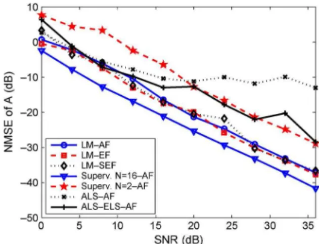
Fig. 2 shows the normalized mean square error (NMSE) of the estimated array response matrix , defined as:
, where is the
1In this work, the updating strategy of follows that of [9].
Fig. 2. NMSE of versus SNR provided by the proposed LM-based method.
number of Monte Carlo simulations, is the matrix esti-mated at the Monte Carlo simulation and denotes the Frobenius norm, versus SNR provided by the proposed LM-based receivers. For comparison, it is also shown the MSE provided by the ALS and ALS-ELS algorithms, and by a supervised technique denoted by least squares–Khatri–Rao factorization [2], all of them using the AF protocol. The super-vised technique assumes that the transmitted symbols are known at the receiver. From thisfigure, it can be concluded that the NMSEs provided by the three proposed receivers are very close and, for high SNRs, significantly smaller than the ones obtained with the ALS and ALS-ELS algorithms. Moreover, the proposed techniques showed a 7 dB gain in SNR with respect to the supervised technique with and a 3.5 dB loss with respect to the supervised technique with , with the same slope. The results concerning the estimation of the matrix are omitted due to lack of space.
REFERENCES
[1] K. J. Ray Liu, A. K. Sadek, W. Su, and A. Kwasinski, Cooperative Communications and Networking. Cambridge, U.K.: Cambridge University Press, 2009.
[2] F. Roemer and M. Haardt, “Tensor-based channel estimation and iterative refinements for two-way relaying with multiple antennas and spatial reuse,”IEEE Trans. Signal Process., vol. 58, no. 11, pp. 5720–5735, Nov. 2010.
[3] A. Y. Kibangou and A. L F. de Almeida, “Distributed PARAFAC based DS-CDMA blind receiver for wireless sensor networks,” in
Proc. SPAWC 2010, Marrakech, Morocco, Jun. 2010.
[4] R. A. Harshman, Foundations of the PARAFAC Procedure: Models and Conditions for an “Explanatory” Multimodal Factor Analysis UCLA Working Papers in Phonetics16th ed. , Dec. 1970.
[5] N. D. Sidiropoulos, G. B. Giannakis, and R. Bro, “Blind PARAFAC receivers for DS-CDMA systems,”IEEE Trans. Signal Process., vol. 48, no. 3, pp. 810–823, Mar. 2000.
[6] N. D. Sidiropoulos, R. Bro, and G. B. Giannakis, “Parallel factor anal-ysis in sensor array processing,”IEEE Trans. Signal Process., vol. 48, no. 8, pp. 2377–2388, Aug. 2000.
[7] A.-J. van der Veen, “Algebraic methods for deterministic blind beam-forming,”Proc. IEEE, vol. 86, no. 10, pp. 1987–2008, Oct. 1998. [8] N. D. Sidiropoulos and X. Liu, “Identifiability results for blind
beam-forming in incoherent multipath with small delay spread,”IEEE Trans. Signal Process., vol. 49, no. 1, pp. 228–236, Jan. 2001.
[9] G. Tomasiet al., “A comparison of algorithms forfitting the PARAFAC model,”Comput. Staistt. Data Anal., vol. 50, pp. 1700–1734, 2006. [10] D. Nion and L. De Lathauwer, “An enhanced line search scheme for
complex-valued tensor decompositions. Application in DS-CDMA,”