Abstract
The dynamic compressive behavior of ice is investigated using a large-sized (37 mm in diameter) modified aluminum split Hopkinson pressure bar (SHPB) with pulse shaper at the strain rate from 500 s-1 to 1200 s-1. A series of relatively stable experimental results of dynamic compressive strength versus strain rate and a linear fitting curve have been obtained by controlling data scatter within 25%. The composition of incident wave has been discussed. The effects of pulse shaper diameter and velocity of striker bar have been tested. The properties and principles of incident wave in different stage has been elaborated when using pulse shaper. A theoretical analysis of pulse shaper and bar size effects on the rising time of incident wave has been conducted. Results show the thickness of pulse shaper is proportional to the rising time. Enlarging the diameter and reducing the velocity of the striker bar could increase the rising time and suppress the dispersion. The diameter and wave impedance of bars also contribute to the rising time.
Keywords
Ice, strain rates, pulse shaper, dynamic compressive strength, SHPB.
Pulse Shaper and Dynamic Compressive Property Investigation on
Ice Using a Large-Sized Modified Split Hopkinson Pressure Bar
1 INTRODUCTION
Various outdoor structures, such as aircrafts, vehicles and buildings, are continually under attack by hail ice storm in air or on the ground. These disasters may cause serious structural damage and functional failure. To improve the performance of these structures on eliminating the damage of hail ice storm hazards, the dynamic mechanical property of ice should be understood well.
Zhenhua Song a,c* Zhihua Wang b Hyonny Kim c Hongwei Ma d
a School of Engineering, Sun Yat-Sen
University, Guangzhou 510006, China. [email protected]
b Institute of Applied Mechanics and
Bio-medical Engineering, Taiyuan University of technology, Taiyuan 030024, China. [email protected]
c Department of Structural Engineering,
University of California at San Diego, La Jolla, CA 92093-0085, United States. [email protected]
d College of Science & Engineering, Jinan
University, Guangzhou 510632, China. [email protected]
*Corresponding author
http://dx.doi.org/10.1590/1679-78252458
Latin American Journal of Solids and Structures 13 (2016) 391-406
The research on ice mechanical property started at the late seventies of the last century by U.S. Navy researcher Haynes (1978). Schulson’s research team (Currier and Schulson, 1982; Nixon and Schulson, 1987; Schulson, 1995, 2005) and Dempsey et al. (1999a, 1999b) investigated the static mechanical properties and crack growth of ice under compressive loading. Tensile and compressive loading tests concluded that the tensile strength of ice is much smaller than that of compressive strength. Under static compressive loading, the ice experienced ductile failure.
Existing studies show that the compressive performance of ice depends significantly on strain rates (Weber and Nixon, 1996). The mechanical property of ice also varied from ductile to brittle under different strain rates (Batto and Schulson, 1993). Schulson (2001) observed this phenomenon that ice is subjected to strain rates in the range from 10-8 s-1 to 10-1 s-1. And these experimental results exhibited extensive scatter at strain rate from 10-3 s-1 to 10-1 s-1. Cole (2001) conducted experiments on ice at strain rates from 10-2 s-1 to 10-1 s-1 to reveal the relationship between the microstructures of different type of ice on its flow and fracture behavior under a wide range of condition. And their results were quite different from Schulson’s experiments data. A series of compression experiments on freshwater ice and sea ice were conducted by Jones (1997) at strain rates from 10-1 s-1 to 10 s-1. The research results show that the strength of freshwater ice is 1.3 times higher than that of sea ice at strain rate of 10 s-1. Compressive strength of ice was been tested by Dutta et al. (2003, 2004) at the strain rates from 10 s-1 to 100 s-1. And largediameter (41.64 mm and 71.12 mm) ice cylinder specimens were employed to measure stress-strain curves at strain rates of 100 s-1 by Fasanella et al. (2006). This report also concluded that when ice fractured under high speed impact, the failure behave more like a fluid, and the loading time history curves were much less dependent on the internal crystalline structure (single crystalline or polycrystalline) of ice. More recently, lake and distilled water large-sized (19 mm diameter)ice cylinderspecimens were tested by Wu and Prakasha (2015) at strain rates in range of 80 s-1 to 600 s-1 using a modified split Hopkinson pressure bar (SHPB) with pulse shaper. For obtaining higher strain rate of ice in SHPB tests, a small diameter (12.5 mm) SHPB and small diameter (10 mm) ice cylinder specimen has been employed by Kim and Keune (2007) to test the stress-strain relationships of ice at 400 s-1 to 2600 s-1 strain rates.
Latin American Journal of Solids and Structures 13 (2016) 391-406 The modified SHPB pulse shaper has been carefully used by researchers when dynamic stress/force equilibrium and constant strain rate requirements could not be achieved by using the SHPB directly (Gong et al. 1990; Ligshitz and Leber, 1994). Frantz et al. (1984) was the first to design a thin disk on the head of the incident bar to increase rising time and eliminate the dispersion of incident wave. An extensive set of materials have been tested by researchers (Hsiao and Daniel, 1998; Togami et al. 1996; Vecchio and Jiang, 2007) and found copper is ideal for the SHPB tests (Rome et al. 1998; Song et al. 2008). Meanwhile, the effect of wave shaping by changing the dimen-sions of the pulse shaper has also been discussed (Song et al. 2007; Sedighi et al. 2010). The recent work by Naghdabadi et al. (2012) show that by reducing the velocity of the striker bar could increase the rising time and suppress the dispersion of incident wave. However, their work also claim that by reducing the diameter of the pulse shaper could achieve the same effect, which is conflict with the conclusions of our theoretical analysis and experimental results. Meanwhile, although pulse shaper is a mature technology to be applied in SHPB testing, there is few research about the theoretical analysis, properties and principles illumination of incident wave in each stage when using pulse shaper.
In this paper, a series of experiments on the dynamic mechanical properties of ice have been conducted by using a large diameter (37 mm) SHPB to reduce the data scatter of compressive strength versus strain rate. The appropriate size and aspect ratio of specimen has been carefully considered to suppress data scatter and eliminate inertia and friction effects. The relationship between compressive strength and strain rate has been researched by using pulse shapers. The properties and principles of incident wave in different stage has been elaborated when using pulse shaper. The effects on waveform shaping by changing the diameter and thickness of pulse shaper have been investigated by experi-ments and theoretical analysis. The effects of varying the velocity of striker bar and the functions of bars parameters on waveform shaping have also been explained.
2 EXPERIMENTAL PROCEDURE
2.1 Ice and Specimens
Latin American Journal of Solids and Structures 13 (2016) 391-406 2.2 Experiments Setup
The dynamic compressive material properties experiments of ice have been conducted by using a split Hopkinson pressure bar (SHPB). For increasing testing sensitivity, an aluminum SHPB system has been chosen for impedance matching.
There are several design considerations in selecting the diameter of the bars, which is almost consistent with the diameter of the specimen. And for the specimen, a thinner geometry is preferred for more easily to achieve stress equilibrium and obtaining high strain rates according to the nominal strain rate defined Equation.
0
n s
v
L
(1)In this equation, is the impact velocity of the striker bar, is the thickness of the specimen. As the reasonable aspect ratio of specimen is set to be a constant, a thinner thickness would match to a smaller diameter of the specimen, and likewise, a smaller diameter of the bars.
However, crystalline brittle weak materials inevitably contain invisible initial cracks. These tiny defects are non-uniformly distributed in the material, which affect the local performance. When the sample is small, the difference between samples would be significant because the local properties of the material are largely the global properties as well. Also, scatter of the mechanical property would be more severe when specimen becomes smaller. Therefore, to eliminate date scatter and differences between specimens in experiments, an appropriate bigger specimen dimension should be chosen.
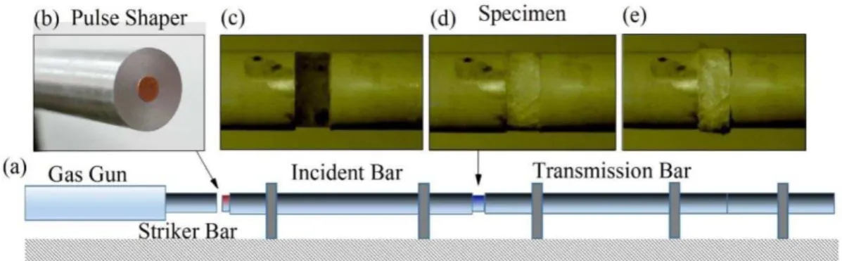
In this research, the balance between strain rates and data scatter has been taken into consider-ation and a SHPB system with a common diameter of 37 mm, which is larger than that of references, has been employed for the ice testing. The diameter and thickness of ice specimen have been set to be 36 mm and 15mm for reasonable aspect ratio(Davies and Hunter, 1963), respectively. The length of striker bar, incident bar, transmission bar and momentum trap bar are 400 mm, 2000 mm, 2000 mm and 600 mm. The SHPB system is shown in Figure 1a. Each strain rate has been tested 4 times to verify the reproducibility and accuracy of the experimental results.
Figure 1: SHPB, pulse shaper and specimen failure procedure.
Latin American Journal of Solids and Structures 13 (2016) 391-406 There are many ways to prevent ice melting during the tests. Kim and Keune (2007) use ice bags to cool down whole incident bar and transmission bar by embracing whole bars into the ice bags for a while. But for such a large (2000 mm length and 37 mm diameter) aluminum bar in our experiments, it hard to cool down the bars enough before the ice bags melted in room temperature circumstance. Since it would be difficult to cool down a 2000 mm long bar in an open air environment, liquid nitrogen has been employed to locally cool just the heads of incident and transmission bar where the specimen has been placed. The heads of the bars were submerged in liquid nitrogen for 30 s. It should be pointed out that although the temperature of liquid nitrogen is -196 degree Celsius, aluminum is a very good thermal conductivity material and only very small part (<5%) of the bar has been submerged into liquid nitrogen for just 30 s, the bar head would be not so cold when rest of the bar has been heated by air during the same time. While the soaking time is precisely controlled, the temperature of bar head would be maintained at the temperature of a little bit lower than 0 degree Celsius for few minutes after removing from liquid nitrogen. Thus, bars heads should be re-cooled once every 4 tests. A very thin layer of petroleum jelly was used to not only make vacuum between the specimen and bars, but also insulate heat and prevent ice melting by bars until the temperature of bar head rises to around 0 degree Celsius (ensure the petroleum is uncondensed).
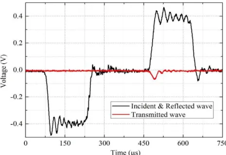
Figure 2: Signals of SHPB testing on ice.
Latin American Journal of Solids and Structures 13 (2016) 391-406
local premature failure on the specimen would be caused by the oscillation, which has no relationship with the material property, and causes errors in the testing results.
Meanwhile, as Figure 2 shows, the rising time of the incident wave is around 20 s. To meet the dynamic stress equilibrium requirements (Chen et al. 2002) in SHPB tests, the wave should traverse 3 to 5 times in the thickness direction of the specimen (Ravichandran and Subhash, 1994). The traverse time is determined by the thickness of the specimen and the wave velocity of the material. For ice specimens, the thickness is much higher than that of other references, and the wave velocity is much slower than that of other metal materials. The minimal rising time to achieve dynamic stress equilibrium as shown in Equation (2).
0
2
3
s6
i27.95
min s
i i
L
t
L
s
C
E
(2)Here the specimen thickness is 15 mm, the density of ice is 900 kg/m3and the young’s module of ice is 9.38 GPa (static state) (Tippmann et al. 2013).
The result of Equation (2) shows that the rising time of incident wave is too short to meet the dynamic stress equilibrium requirement in SHPB tests on the ice specimen in this experiment. And Wu and Prakasha (2015); Shazly et al. (2009) elaborated the necessity of using pulse shaper for obtaining stress equilibrium in SHPB testing when large-sized ice specimen has been employed. In summary, a pulse shaper is indispensable for adjusting the incident wave in SHPB experiments on ice.
3 PULSE SHAPER DESIGN
3.1 Composition and Mechanism of Incident Wave
There are three basic assumptions in SHPB testing: (i) One-dimensional stress wave propagation; (ii) Dynamic stress/force equilibrium; (iii). Constant strain rate. Three-dimensional stress wave propaga-tion, caused by the transverse inertia effect of the bars, is the reason of dispersion of the incident wave and should be controlled for meeting the assumption (i). The wave should traverse 3 to 5 times (Ravichandran and Subhash, 1994) in the thickness direction of the specimen during the rising time of the incident wave to meet assumption (ii). For the elastic brittle material, such as ice, it is difficult to maintain a constant strain rate during tests as required in assumption (iii) using only the bars themselves. A pulse shaper should be employed to adjust the waveform and fulfill the requirements of these three assumptions in testing.
A pulse shaper is a disk attached to the head of incident bar, as Figure1b shown. When struck, the pulse shaper softens the impact force by elastic and plastic deformation, which has the effect of increasing the rising time of the incident wave and changes the waveform thereby eliminating the dispersion at the same time (Gong et al. 1990).
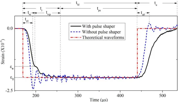
Latin American Journal of Solids and Structures 13 (2016) 391-406 As Figure 3 shown, the waveform is assumed to be rectangular during impact (as red dashed curve) in ideal state. However, force/stress loading stage inevitably requires a process due to the elastic contacting between two bars, the waveform is not perfectly rectangular as a finite time is required to achieve the fully contact, that is, the contact force/stress from 0 to a stable/maximum level. This time period is defined as the rising time of the incident wave. Similarly, there is an unloading time in the wave.Meanwhile, due to the unavoidable transverse dimension of bars, dis-persion exists when the wave propagates along the length. It appears as the high frequency oscillation of the waveform (dashed bluecurve). The original rising and unloading time of bar impact are shown as and in Figure 3, respectively. The response appears linear since the contacting and dynamic response of bars are elastic. When a pulse shaper is placed between the striker and the incident bars, the incident wave (as black curve) could be divided into three parts: rising period , plateau period
and unloading period .
Figure 3: Composition of incident wave.
In the rising period , there are two stages: and . The is the first rising stage of the rising period, during which the response of bars and pulse shaper is elastic; the second rising stage is the period of elastic response of the bars and plastic response of pulse shaper. The turning point between and is the time that the stress in pulse shaper reaches the yield stress of the material (copper).
Latin American Journal of Solids and Structures 13 (2016) 391-406
compressed after this. The value of this maximum compressed stress in bars is shown in Equation (3).
0 0 0
1
2
bC v
b
(3)Here is the density of bar material and is the wave velocity in bars material. In the unloading period , both bar and pulse shaper experience elastic unloading.
It is notable that the parts of elastic and plastic response during the loading period and the elastic response of the pulse shaper during the unloading period increase the response time of rising and unloading and also increase the width of incident wave. Therefore, when a pulse shaper has been used in SHPB, the length of incident bar should be more than twice that of the striker bar. However, the references (Naghdabadi et al. 2012) attributes the contribution of the waveform changes exclusively to the pulse shaper and not influenced by the bars. Therefore, an experimental and theoretical analysis has been conducted.
3.2 Experimental and Theoretical Analysis of Incident Wave
For testing the effect of varying velocities of striker bar on changing the waveform of the incident wave, a series of experiments with the velocity of striker bar ranging from 10 m/s to 20 m/s have been conducted using a pulse shaper with a thickness of 0.25 mm and diameter of 8 mm, as shown in Figure 4.
Latin American Journal of Solids and Structures 13 (2016) 391-406 By increasing the velocity of the striker bar, the signal of stable/maximum stress has been in-creased and the rising time has been dein-creased. The high-frequency oscillation, which was caused by dispersion, also becomes seriously further.
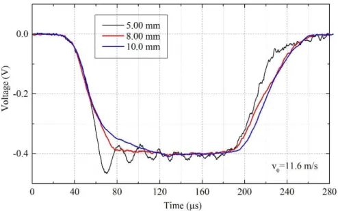
A series of experiments with different diameters of pulse shaper has also been conducted at 11.6 m/s as shown in Figure 5. When the diameter of pulse shaper increased, there was no change in the stable/maximum stress strength, but the rising time and dispersion of the incident wave have been increased and suppressed better, respectively, which were in contradiction to references listed in ref-erences (Naghdabadi et al. 2012).
For verifying the results, a theoretical analysis has been performed as shown in Figure 6. When the striker bar first impacts/contacts the incident bar, the time is set to 0. And the end of the elastic response is the time point - where the copper pulse shaper reaches yield strength. Therefore, this impact stage which we investigate here is an elastic dynamic response and all the deformation of the materials is elastic.
Figure 5: Incident waves with different diameter of pulse shaper.
Figure 6: Impact procedure schematic.
Latin American Journal of Solids and Structures 13 (2016) 391-406
the particle stress, strain energy, kinetic energy differential and mass could be defined as following Equations, respectively:
0
1
2
C v
(4)
0 0 0
1
1
2
2
re
V t
U
dV
t
t AC dt
(5)
dW
v vdm mdv
(6)0
m
V
AC t
(7)where ρis the density of the material, is the velocity of the particles, is the wave velocity in that material, εis the strain of that particles, Ais the cross section,Vis volume and the
m
is the mass ofthe particles.
As the dynamic stress/force equilibrium assumption, the following equation should hold true:
c
A
c bA
b
(8)where the subscript c represents the copper/pulse shaper and b represents the bars.
Due to the elastic dynamic response, the strain energy and kinetic energy of pulse shaper in this elastic procedure is:
2
2 0
1
1
1
2
2
2
4
V yc
c c yc c
c c
U
dV
A d
A d
E
E
(9)2 2 2 0 0 0 0
2
2
rev t yc c
c
c c c
c c re c c
A d
W
vmdv
A tdt
C t
C
(10)where
d
is the thickness of pulse shaper andE
is Young’s module.The strain energy and kinetic energy increase of the incident bar in this procedure is:
2
2 2
0 0 0
0 0
1
1
1
2
2
6
re re
t t yc c
i i i b b b b yc b c re
b re b b b
A
U
t
t A C dt
t
A C dt
C A t
E
t A
E A
(11)2 2 2 2
2 2
2
0 0 0
0 0
8
8
3
re
m v t yc c yc c
i re
b b b re b b b
A
A
W
v dm
vmdv
t dt
t
C A t
C A
(12)The strain energy and kinetic energy variation of striker bar in this procedure is:
2 2
0
1
6
sk i yc b c re
b b
U
U
C A t
E A
Latin American Journal of Solids and Structures 13 (2016) 391-406
2 2 2 2
2 2 2
0 0 2 0 0
0 0
8
8
1
1
2
2
3
re
t yc c yc c
sk b b b re re
b b b re b b b
A
A
W
mv
t dt
A C t v
t
C A t
C A
(14)Since energy is conserved, then
sk sk i i c c
W
U
W
U
W
U
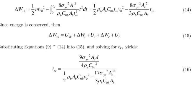
(15)Substituting Equations (9) ~ (14) into (15), and solving for yields:
2 2 0 2 2 2 0 0 0
9
4
17
1
2
3
yc c c c re yc c b b bb b b
A d
C
t
A
A C v
C A
(16)By Equation (16), it showed that reducing the velocity of striker bar and adding thickness of pulse shaper
d
would increase , which agrees with the experimental results and references (Nagh-dabadi et al. 2012). Meanwhile, increasing cross-sectional area of pulse shaper would also in-crease , which agrees with experimental results and is opposite to the results in references (Nagh-dabadi et al. 2012). Furthermore, the cross-sectional area and wave impedance of bars also contribute to the rising time.According to the experimental results and theoretical analysis, a series of velocities of the striker bar versus the size of pulse shaper have been obtained as shown in Table 1.
Velocity of striker bar Diameter of pulse shaper Thickness of pulse shaper
10 m/s 8.0 mm 0.25 mm
15 m/s 9.0 mm 0.25 mm
20 m/s 10.0 mm 0.25 mm
25 m/s 11.0 mm 0.25 mm
Table 1: Velocity of striker bar versus size of pulse shaper
Latin American Journal of Solids and Structures 13 (2016) 391-406
4 RESULT AND DISCUSSION
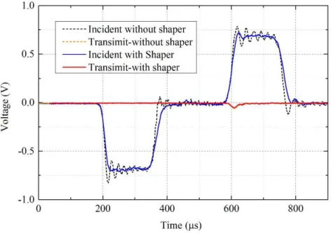
The test signals, which were obtained from the incident and transmission bar by using and without using pulse shaper are shown in Figure 7. The dispersion has been well suppressed and the rising time has been increased as expected when pulse shaper has been employed. Meanwhile, the amplitude of high-frequency oscillation has also been suppressed to a much lower level than that of transmitted wave.
Figure 7: Signals contrast of SHPB testing with and without pulse shaper.
Using the SHPB system, time histories for the incident, reflected and transmitted wave signals were obtained using strain gauges on the incident and transmission bar. As the classic Equation (17) of SHPB (Togami et al. 1996), the engineering stress, strain and strain rate could be calculated by the strains of the incident, reflected and transmitted wave.
0 0 ˙
0
2
b b
s i r t
s
t
s i r t
s
s i r t
s
E A
t
A
C
t
dt
L
C
t
L
(17)where , and are strains of incident, reflected and transmitted wave, respectively. The subscript s means that of specimen.
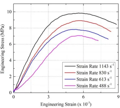
Latin American Journal of Solids and Structures 13 (2016) 391-406 sensitive and the slope of the curves steepens with the increase in strain rate. In addition, the peak stress of ice increases significantly with the increase in strain rate. The failure strain is around 0.5 % and stress-strain curve appears similar to that of a brittle material when it is under 0.5% deformation. However, at higher stresses, just prior to reaching the peak stresses, the ice appears to be in a state between solid and fluid-like materials, and the curve is no longer linear. After that, unloading process is relatively slow when compared to brittle or ductile materials. This appearance agree with the description of ice failure under impact in report of Fasanella et al (2006) and the curve shape agree with that type of curve in other references Shazly et al. (2009).
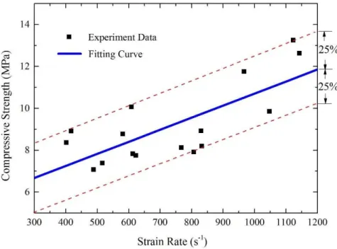
To understand the relationship between peak strength and strain rate of ice, the experimental data (including scattering data) were plotted in Figure 9 and a linear curve fitted through them has also been obtained as Equation (18):
ip
a
ib
(18)where
a
0.005778
andb
4.922
.Figure 8: Dynamic stress-strain curves at different strain rates.
Latin American Journal of Solids and Structures 13 (2016) 391-406
Figure 9: Data and fitting curve of compressive strength versus strain rate.
There are many reasons affect the dynamic strength of ice. Water types (Jones, 1997; Wu and Prakasha, 2015) and purification (Kim and Keune, 2007) of ice are most significant reasons. In this research, deionized water is used to make ice, which is different from that in other reference. And Shazly et al. (2009) prove that the dynamic strengths of ice in -30 degree Celsius are higher than that of -10 degree Celsius, which means that temperature of ice is a crucial factor affecting its dynamic strength. In this testing, even the ice specimens are stored in -16 degree Celsius for at least 24 hours and bars heads are cooled down by liquid nitrogen, the ice specimens still been exposed at room temperature for a few seconds when placing specimen at bars heads and triggering the gas gun system of SHPB. That might slightly affect the strength of ice. And this environment temperature is more close to the real engineering case, such as that of hail ice impact on ground buildings and vehicles.
The experimental data show 25% scatter to the fitted curve in Figure 9. This is because ice is composed of crystals which inevitably contain uneven invisible small cracks. Also, the material prop-erties are changed slightly when subject to the room temperature environment. However, the 25% data scatter could still be acceptable and the data is more consistent with the fitted curve overall than statistic results (Tippmann et al. 2013) of other references (>100% data scatter).
5 CONCLUSIONS
Latin American Journal of Solids and Structures 13 (2016) 391-406 1) Dispersion phenomena and the rising time of incident wave has been suppressed and
in-creased by increasing the diameter of pulse shaper. The rising time decreases and dispersion becomes seriously with the increasing of the striker bar velocity.
2) By theoretical analysis, the thickness of pulse shaper is proportional to the rising time. The cross-sectional area and wave impedance of bars also contribute to the rising time. 3) Ice are strain-rate sensitive and the slope of the curves steepens with the increase in strain rates. The peak compressive strength of ice increases significantly with the increase in strain rates. The failure mode of ice is crush and the failure strain is around 0.5%.
4) A modified large-sized (37mm diameter) SHPB with pulse shaper is more suitable for test-ing brittle crystal weak materials (ice), than smaller ones without pulse shaper for obtaintest-ing less scattering experimental data in dynamic mechanical property tests. And the scatter of this research experimental results has been well controlled within 25%.
Acknowledgements
The authors of this paper acknowledge the financial supports of the Chinese National Science Foundation (NSFC 11032005). The authors also acknowledge the assistance of Dr. Daniel Whisler for helping to improve the quality of the language in this paper.
References
Batto R.A., Schulson E.M., (1993). On the ductile-to-brittle transition in ice under compression. Acta Metall Mater. 41, 2219-25.
Chen W., Lu F., Winfree N., (2002). High-strain-rate compressive behavior of a rigid polyurethane foam with various densities. Exp Mech. 42, 65–73.
Cole D.M., (2001). The microstructure of ice and its influence on mechanical properties. Eng Fract Mech. 68, 1797– 822.
Currier J.H., Schulson E.M., (1982). The tensile-strength of ice as a function of grain-size. Acta Metall. 30(8), 1511–4. Davies E.D.H., Hunter S.C., (1963). The dynamic compression testing of solids by the method of the split Hopkinson pressure bar. J Mech Phys Solids. 11,155-79.
Dempsey J.P., Defranco S.J., Adamson R.M., Mulmule S.V., (1999a). Scale effects on the in-situ tensile strength and fracture of ice. Part I: Large grained freshwater ice at Spray Lakes Reservoir, Alberta. Int J Fracture. 95, 325–45. Dempsey J.P., Adamson R.M., Mulmule S.V., (1999b). Scale effects on the in-situ tensile strength and fracture of ice. Part II: First-year sea ice at Resolute, NWT. Int J Fracture, 95, 347–66.
Dutta P.K., Cole D.M., Schulson E.M., Sodhi D.S., (2003). A fracture study of ice under high strain rate loading. Proc of the 37th Intern offshore and polar Eng Conf. p.465-472.
Dutta P.K., Cole D.M., Schulson E.M., Sodhi D.S., (2004). A fracture study of ice under high strain rate loading. Int J Offshore Polar. 14, 182-8.
Fasanella E.L., Boitnott R.L., Kellas S., (2006). Dynamic Crush Characterization of Ice. NASA/TM-2006-214278 ARL-TR-3753.
Frantz C.E., Follansbee P.S., Wright, W.T., (1984). New experimental Techniques with the Split Hopkinson Pressure Bar. Proc 8th Intern Conf on High Energy Rate Fabrication, Texas, p.229-36.
Latin American Journal of Solids and Structures 13 (2016) 391-406
Haynes F.D., (1978). Effect of temperature on the strength of snow-ice. CRREL-78-27, Army Corps of Engineers. Hsiao H.M., Daniel I.M., (1998). Dynamic compressive behavior of thick composite materials. Exp Mech. 38, 172-80. Jones S.J., (1997). High Strain-Rate Compression Tests on Ice. J Phys Chem B. 101, 32: 6099-6101.
Kim H., Keune J.N., (2007). Compressive strength of ice at impact strain rates. J Mater. 42, 2802-6.
Ligshitz J.M., Leber H., (1994). Data Processing in the split Hopkinson pressure bar tests. Int J Impact Eng. 15, 723-33.
Naghdabadi R., Ashrafia M.J., Arghavanic J., (2012). Experimental and numerical investigation of pulse-shaped split Hopkinson pressure bar test. Mat Sci Eng A-Struct. 539, 285–293.
Nixon W.A., Schulson E.M., (1987). A micromechanical view of the fracture-toughness of ice. J Phys Coll C. 48, 313– 9.
Ravichandran G., Subhash G., (1994). Critical appraisal of limiting strain rates for compression testing of ceramics in a split Hopkinson pressure bar. J Am Ceram Soc. 77, 263-7.
Rome J., Isaacs J., Nemat-Nasser S., (1991). Hopkinson techniques for dynamic recovery experiments. Proc Royal Soc. 435, 371-91.
Schulson E.M., (1999). The structure and mechanical behavior of ice. J Min Met Mat S. 51, 21–7. Schulson E.M., (2001). Brittle failure of ice. Eng Fract Mech. 68, 1839-87.
Schulson E.M., Iliescu D., Frott A., (2005). Characterization of ice for return-to-flight of the space shuttle. Part 1 – Hard ice. NASA CR-2005-213643-Part 1.
Sedighi M., Khandaei M., Shokrollahi H., (2010). An approach in parametric identification of high strain rate consti-tutive model using Hopkinson pressure bar test results. Mat Sci Eng A-Struct. 527, 3521-8.
Shazly M., Prakash V., Lerch B.A., (2009). High strain-rate behavior of ice under uniaxial compression. Int J Solids Struct. 46, 1499-515.
Song B., Chen W., Antoun B.R., Frew D.J., (2007). Determination of early stress for ductile specimens at high strain rates by using an SHPB. Exp Mech. 47, 671-80.
Song B., Syn C.J., Grupido C.L., Chen W., Lu W.Y., (2008). A Long Split Hopkinson Pressure Bar (LSHPB) for Intermediate-rate Characterization of Soft Materials. Exp Mech. 48, 809-15.
Tippmann J.D., Kim H., Rhymer J.D., (2013). Experimentally validated strain rate dependent material model for spherical ice impact simulation. Int J Impact Eng. 57, 43-54.
Togami T.C., Baker W.E., Forrestal M.J., (1996). A split Hopkinson bar technique to evaluate the performance of accelerometers. J Appl Mech. 63, 353-6.
Vecchio K.S., Jiang F., (2007). Improved Pulse Shaping to Achieve Constant Strain Rate and Stress Equilibrium in Split-Hopkinson Pressure Bar Testing. Metall and Mat Trans A. 38, 2655-65.
Weber L.J., Nixon W.A., (1996). Fracture toughness of freshwater ice. Part1. Experimental technique and results. J Offshore Mech Arctic Engng. 118, 135–40.