ABSTRACT: A series of geometric models of lobed nozzles with a central plug was created by different scalloping positions and widths. The shapes of lower and upper edges, cutting depth were kept unchanged. In this study, by the use of numerical simulation, the effects of scalloped width and position on the performance of jet mixing in the pumping condition were analyzed. The results indicated that, as the position of scalloped lower edge kept constant, the radial position of the accelerated mixing region of sidewalls did not change. The accelerated mixing region is enlarged as scalloped width increased, while the growth rate of enlarged region is less than the growth rate of scalloping width. When the scalloped region with the same width moved outward in the radial direction, the mixing rate of the region of the lobe outer edges increased. However, the distance for complete mixing of the primary stream in the core region was increased. It was also found that inward moving of scalloped lower edge enhanced the effect of strengthening streamwise vortices but induced more pressure loss.
KEYWORDS: Lobed nozzles, Scalloping, Thermal mixing eficiency, Streamwise vorticity, Numerical simulation.
The Effects of Scalloping Width and
Position on Jet Mixing of Lobed Nozzles
Liu DaWei1, Huang Jun1, Sheng Zhiqiang1, Ji Jinzu1
INTRODUCTION
Lobed nozzles can increase the interface area of primary and secondary low (Elliott et al. 1992) and the interaction between streamwise and normal vorticity can enhance the mixing between primary and secondary low (Povinelli and Anderson 1984; McCormick and Bennett 1994). Such ejector schemes provide a simple mean of reducing jet noise by mixing high velocity primary low with cool ambient air which can also provide a thrust gain (Presz et al. 1994; Acheson et al. 2011). For the military infrared stealth purpose, the lobed nozzles can dilute the engine plume with cold ambient air, decrease CO2 concentration and temperature; therefore it reduces the target detectability (Pan et al. 2013; Zhang et al. 2014). Meanwhile, from the fuel savings, full fuel combustion can be achieved by enhancing the mixing of reactants while delaying ignition in a controlled manner (Smith et al. 1997; Mitchell et al. 2004). Previous studies show that the scalloping of lobed nozzles can improve the mixing performance (Presz et al. 1994; Abolfadl and Sehra 1993; Yu et al. 1997, 2000; Hu et al. 1999; Mao et al.
2009; Lei 2011) but cause some extra total pressure loss (Hu
et al. 1999). Presz et al. (1994) found that the scalloping could generate additional vortices, which are upstream the lobe exit plane. he scalloped lobes with large angle can generate beneits like lower wall friction loss and more rapid mixing. hen a short compact ejector is feasible. Yu attributed the enhancement to that, and the streamwise vorticity is stronger because of some additional streamwise vortices formed due to the scalloping (Yu
et al. 1997). hrough the scalloping of sword alternating lobed nozzle, Sheng et al. (2014) found that the degree of scalloping was increased, and the mixing in the downstream region of the lobe peak was accelerated; however, the primary low in
1.Beijing University of Aeronautics and Astronautics – School of Aeronautic Science and Engineering – Beijing – China.
Author for correspondence: Liu Dawei | Beijing University of Aeronautics and Astronautics – School of Aeronautic Science and Engineering | Beijing 10019 – China Email: [email protected]
center needed larger mixing length. Lei found that the overall streamwise circulation was not necessarily increased after scalloping. In an experimental investigation of a scalloped mixer, Lei (2011) showed that the overall streamwise circulation was not necessarily increased ater scalloping. he more rapidly decaying streamwise vorticity presented a more efective mixing process because of smaller-scale but more developed vortices (Lei 2011; Lei et al. 2012; Wright et al. 2013).
All the previous works on scalloped lobed nozzles were concentrated on large lobe penetration angles lobe nozzles. However, in practical applications of helicopter or warship, designers have preferred small angle lobed nozzles. Because the diameter of mix tube is limited, small lobe penetration angles can penetrate the sidewalls of mix tube. Large angle lobe may cause the primary stream impacting the sidewalls, then the temperature of sidewalls and the pressure loss increase. Also, no parametric studies were performed on these previous studies; in general, scalloping parameters like width, depth, shape, and position were coupled together. In this work, the effects of scalloping width and position on the jet mixing in pumping condition were analyzed numerically. To achieve this, a series of small angle lobed nozzle models with a central plug and different scalloping positions and widths were used. The lower and upper edges and cutting depth were kept unchanged.
INVESTIGATED CONFIGURATIONS
The geometry model of lobed nozzles with a central plug (PLN) and mixing tube are illustrated in Fig. 1. The abbreviations for diameter and radius are D and R, respectively. The annular entrance of the nozzle is formed by two circles with diameters of 210 and 400 mm. The inward and outward lobe penetration angles are 12.9° and 12.1°, respectively. The length of mixing duct is 1,150 mm and its entrance is 100 mm ahead of the exit of the nozzle. The diameter D of the duct is 700 mm, and the length-to-diameter ratio of the mixing segment L/D is 1.5.
Figure 2 shows the scalloped lobed nozzles which are investigated in this paper, and the geometrical dimensions for each scalloping are shown in Fig. 3. he scalloped lobed nozzles No 1, 2, and 3, i.e. scalloping No 1, 2, and 3 (S1, S2, and S3), have the same cut shape, but with the radial cut position moving towards outside in an equal distance. Scallopings No 4 and 5
Figure 1. Geometry dimensions of the baseline lobed mixer
(all dimensions are in mm).
Figure 2. The scalloped lobed nozzles schemes.
(S4 and S5) also have the same cut shape, and the lower and upper edges of S4 lap over with the lower edge of S1 and the upper edge of S2, and those of S5 lap over with the lower edge of S2 and the upper edge of S3. Scalloping No. 6 (S6) has the largest cut width with the lower and upper edges lapping over with the lower edge of S1 and the upper edge of S3, respectively.
CFD MODEL
he numerical simulation domain and grids are illustrated in Fig. 4. Owing to the complicated geometry shapes, tetrahedral cells were adopted to discretize the whole low-ield domain. hree boundary layer cells were used and the irst layer height
S3
S6 S2
S5 S1
Figure 3. Geometry dimensions of each scalloping alternating lobed nozzle (all dimensions are in mm).
Figure 4. Numerical simulation of low-ield domain and grids.
was 0.05 mm. Also in Fig. 4, a reined domain was adopted near the region where severe changes in the velocity and temperature were expected. In the refined domain, the maximum grid size was about 15 mm, and more than 20 million tetrahedral cells were meshed. Total number of cells in the whole low-ield was more than 23 million.
The flow-field simulation is based on Fluent software packages. hree-dimensional Reynolds averaged N-S equations were solved. According to previous studies (Sheng et al. 2014; Sheng et al. 2015), the most appropriate turbulence model is the SST k-ω. he far-ield boundary condition was set to pressure inlet and pressure outlet. he operating pressure was 101,325 Pa, the temperature was 300 K and the turbulence intensity was set to 5%. The discretized scheme was second-order. The
Figure 5. Velocity vector and axial velocity distributions of
the six lobes nozzles. Comparison of (a) Experimental data with (b) Numerical results.
jet inlet velocity was set to 125 m/s and temperature was 850 K. Energy equation was involved in the simulation. In this paper, the wall heat transfer and thermal radiation were not coupled, thus the boundary condition of adiabatic wall was used.
CFD MODEL VALIDATION
To quantify the numerical method, a comparison against the available experimental results (Hu et al. 2000, 2005) is performed for the velocity vector and axial velocity distributions. he lobed nozzle in Hu’s experiment has six lobes. he width of lobe is 6 mm, and the height of the lobe is 15 mm. The inward and outward lobe penetration angles are 25° and 14°, respectively. he diameter of the lobed nozzle is d = 40 mm. he jet velocity at the exit of the tested nozzle is set at about 20 m/s. he Reynolds number of the jet low, based on the lobed nozzle diameter and the jet velocity, is about 55,000. Particle Image Velocimetry (PIV) system, called Dual-Plane Stereoscopic PIV (DP-SPIV), was used to measure the mixing low results.
The results are illustrated in Fig. 5, where 20, 60 and 80 mm are the distances from the nozzle exit. It can be seen that the simulated results compare well with the experimental data. Figure 6 displays the mixing decay of the maximum value of the streamwise vorticity in the simulation and Hu’s experiment. Except for some diferences ater the breakdown, the simulated maximum value of the streamwise vorticity has a good agreement. According to the corresponding references (Hu et al. 2000, 2005), the major part of the enhanced mixing caused by the special geometry of the lobed nozzle is concentrated within the irst two diameters
DP-SPIV 20 mm
SST k-w 20 mm
60 mm
60 mm (a)
(b)
120 mm
RESULTS AND DISCUSSION
JET MIXING FLOW-FIELD ANALYSIS
Figure 7 shows the axial velocity isolines and temperature cloudscape at x/d = 0.25 and 0.5. As can be seen in this igure, the mixing of wave trough is more rapid than the lobe peak and sidewall region for the PLN; with a constant scalloping width, the improved mixing regions of conigurations S1, S2 and S3 change on the radial direction with the scalloping position (see Figs. 7b, 7c and 7d). he improved mixing regions of S4 are almost equal to that of S1; that of S5 is almost equal to that of S2; and that of S6 is almost equal to that of S4; the unmixed primary stream near the lobe peaks of S4 is less than that of S1 but more than that of S2; that of S5 is less than that of S2 but more than that of S3; and that of S6 is less than that of S4 but more than that of S5 (Figs. 7e, 7f, and 7g). As the position of scalloped lower edge kept invariant, the radial position of the accelerated mixing region of sidewalls did not change. he accelerated mixing region is enlarged as scalloped width increased, while the growth rate of enlarged region is less than the growth rate of scalloping width.
STREAMWISE VORTICITY
Figure 8 shows the non-dimensional streamwise vorticity distribution at x/d = 0.25 for each lobed nozzle. he streamwise vorticities of S1, S4 and S6 are higher than other scalloped schemes and PLN. One can deduce that inward moving of of the lobed nozzle, thus the diference in the maximum value of
the streamwise vorticity ater the vortices break down only has slight inluence on the accuracy of the simulated jet mixing. herefore, these results validate that the numerical method is suitable for the simulation of the lobed nozzles in this study.
he dimensionless streamwise vorticity ωx (Hu et al. 2005) is deined as:
where:
Figure 7. Distributions of axial velocity (m/s) and temperature at 0.25 d and 0.50 d for each lobed nozzle.
wx
ma
x
x/d
DP-SPIV SST k-w 5.0
4.0
3.0
2.0
1.0
0.0
0.0 0.50 1.00 1.50 2.00 2.50 3.00
Figure 6. The maximum value of the streamwise vorticity of
the lobed nozzle with six lobes.
D is the diameter of the mixing duct; v and w are the
velocities of mixing stream in the y and z directions; upis the initial velocity of the primary stream.
(1)
(a)
0.50 d 0.50 d 0.50 d 0.50 d 0.50 d 0.50 d 0.50 d
PLN 0.25 d S1 0.25 d S2 0.25 d S3 0.25 d S4 0.25 d S6 0.25 d S6 0.25 d
Figure 8. Distributions of the non-dimensional streamwise vorticity at 0.25 d for each lobed nozzle.
Figure 9. 700K temperature isosurface for each lobed nozzle.
scalloped lower edge enhances the effect of strengthening streamwise vortices.
Figure 9 shows the 700 K temperature iso-surface for each lobed nozzle. he mixing near the sidewalls of PLN is slightly faster than that in the region near the lobe peaks. he scalloping accelerates the mixing in the downstream regions of the lobe peaks and sidewalls, but the complete mixing distance of the primary stream in the core region increases. For the mixing near the sidewalls of all the schemes, the scheme S4 is faster than S1 and S2; S5 is faster than S2 and S3; S6 has the highest mixing rate in these regions. he mixing rate increases as the scalloping width increases. In the region near the lobe peaks, all scalloped schemes mixing rate are higher than PLN. When the scalloped region with the same width (S1, S2, S3) moves outward in the radial position, the mixing rate increases. he complete mixing distances of the primary stream in the core region for all scalloped schemes are almost the same, except S3, which has slightly shorter complete mixing distance. he scalloping accelerated the mixing of sidewalls region. Part of the mixing air lowed to the core region, and the temperature of secondary low penetrating into the core region increased. herefore, the complete mixing distances of the primary stream in the core region increased. he scalloped inner edge of S3
is farther to the core region, less mixing air lows to the core region, and the complete mixing distance of core region for S3 is slightly shorter than other scalloped schemes.
JET MIXING PERFORMANCE
In the present investigation, the components of primary and secondary streams are treated as the same. he thermal mixing eiciency η t r (Xie and Liu 2011) can be expressed as:
where:
m p and m s are the mass flux of primary and secondary stream, respectively; m m is the mass lux of the local mixing stream; the parameters Tp and Ts are the initial temperature of primary and secondary streams; Tm is the temperature of the local mixing stream; TM (Xie and Liu 2011) is the temperature for the complete mixing stream of the primary and secondary streams, i . e . :
(2)
(3)
(a)
(a) PLN
PLN
S1
S1
S2
S2
S3
S3
S6
S6 S5
S5 S4
S4 (b)
(b)
(c)
(c)
(d)
(d)
(e)
(e)
(f)
(f)
(g)
Figure 10. Thermal mixing eficiency along the axis for each lobed nozzle.
Figure 11. The total pressure recovery coeficients of
cross-sections along the lobed nozzles. hermal mixing eiciency is a vital factor of jet mixing.
It indicates the degree of uniform mixing of the primary and secondary streams. he thermal mixing eiciencies against x / d
is plotted in Fig. 10, where x is the axial distance measured from the exit of the nozzle. Figure 10 shows that the thermal mixing eiciencies for all the lobed nozzles increase rapidly from 0.25 d
to 1.0 d and then slow down. The values for the scalloped schemes are higher than the PLN scheme. In the range of 2.0 d to 2.5 d , only the S3 scheme index value is higher than the PLN. For the thermal mixing eiciencies of all the scalloped schemes, the values are similar as the scalloped widths kept invariant and increase if the scalloped width is enlarged in the range from 0.25 d to 0.5 d ; while in the range of 1.5 d to 2.5 d , the scalloped inner edge is a decisive factor, a higher thermal mixing eiciency can be achieved by the outward moving of scalloped inner edge. All these results indicate that in a short mixing distance, the accelerated mixing of sidewalls region for the scalloped schemes is the primary cause for thermal mixing eiciency improving. As the mixing distance increases, the inluence of mixing in the downstream of the lobe peaks and core region becomes more important. As can be seen in Fig. 8, the streamwise vorticity of S1, S4 and S6 are higher than other scalloped schemes; however, the thermal mixing eiciencies of these schemes do not improve. It can be concluded that the streamwise vortices more intensiied by the scalloping do not bring more enhancement on the mixing efectiveness.
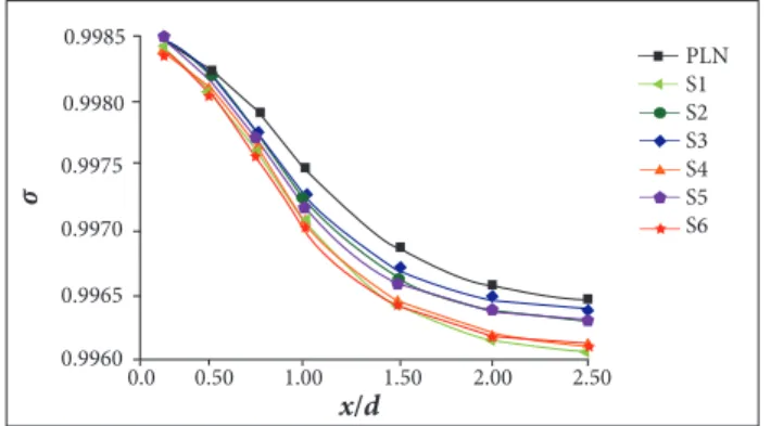
THE TOTAL PRESSURE RECOVERY COEFFICIENT Another important performance parameter for jet mixing is the total pressure recovery coeicient. A superior total pressure recovery coeicient signiies less energy being consumed in the mixing. he equation is given by (Zhang and Li 2006):
where:
P *m is the total pressure of the local mixing stream. The initial total pressure of primary and secondary stream are expressed as P*p and P*S.
It can be seen from Fig. 11 that the total pressure recovery coefficients of cross-sections along the lobed nozzles decreased rapidly up to 1.5 d, then it slowed down. The coefficients of all scalloped schemes are lower than the PLN scheme between 0.5 d and 2.5 d. The scalloping inner edge is a decisive factor for the total pressure recovery coefficient. Only a slight variation of the total pressure recovery coefficient was found for the configurations S1, S4, S6, in which the inner edge was closely located. The total pressure loss increases as the inner edge moves inside. According to previous analysis (Fig. 8), compared to other schemes, S1, S4 and S6 enhanced the effect of strengthening streamwise vortices more significantly but induced more pressure loss at 0.25 d. Therefore, if the scalloping strengthens streamwise vortices more significantly, more pressure loss will be caused.
ηtr
x/d
PLN S1 S2 S3 S4 S5 S6 1.0
0.8 0.9
0.7
0.6
0.5
0.4
0.0 0.50 1.00 1.50 2.00 3.50
σ
x/d
PLN S1 S2 S3 S4 S5 S6 0.9985
0.9980
0.9975
0.9970
0.9965
0.9960
0.0 0.50 1.00 1.50 2.00 2.50
CONCLUSIONS
A series of geometric models of lobed nozzles with central plug were created by diferent scalloping positions and widths. he shapes of lower and upper edges, cutting depth were kept unchanged. By the use of numerical simulation, the efects of scalloped width and position on the performance of jet mixing in the pumping condition were analyzed. he results are summarized as follows:
• As the degree of scalloping increased, the mixing in the downstream regions of the lobe peaks and sidewalls were accelerated; however, the primary low in center needed a larger mixing length. When the position of scalloped lower edge kept invariant, the radial position of the accelerated mixing region of sidewalls did not change.
• When the scalloped region with the same width moved outward in the radial, the mixing rate of downstream
lobe peak region increased. he accelerated mixing region was enlarged as scalloped width increased; however, the growth rate of enlarged region was less than the growth rate of scalloping width.
• he inward moving of scalloped lower edge enhanced the efect of strengthening streamwise vortices; however, the strengthened streamwise vortices by the scalloping did not bring higher mixing efectiveness but induced more pressure loss.
REFERENCES
Abolfadl MA, Sehra AK (1993) Experimental investigation of exhaust system mixers for a high bypass turbofan engine. AIAA-93-0022. Proceedings of the 31st Aerospace Sciences Meeting; Reno, USA.
Acheson KE, Marques EC, Moore MD (2011) A partial mixer nozzle for turbofan nacelles to provide signiicant jet mixing control. AIAA-11-3189. Proceedings of the 29th AIAA Applied Aerodynamics Conference; Honolulu, Hawaii.
Elliott JK, Manning TA, qiu YJ, Greitzer, EM, Tan CS, Tillman TG (1992) Computational and experimental studies of low in multi-lobed forced mixers. AIAA-92-3568. Proceedings of the 28th Joint Propulsion Conference and Exhibit; Nashville, USA.
Hu H, Kobayashi T, Saga T, Sage T, Taniguchi, N, Liu HX, Wu SS (1999) Research on the Rectangular Lobed Exhaust Ejector/Mixer Systems. Trans Jpn Soc Aeronaut Space Sci 41(34):187-192.
Hu H, Kobayashi T, Saga T, Segawa S, Taniguchi N (2000) Particle image velocimetry and planar laser-induced luorescence measurements on lobed jet mixing lows. Exp Fluids 29:141-157. doi: 10.1007/s003480070016
Hu H, Saga T, Kobayashi T (2005) Dual-plane stereoscopic PIV measurements in a lobed jet mixing low. AIAA-05-0443. Proceedings of the 43rd AIAA Aerospace Sciences Meeting and Exhibit; Reno, USA.
Lei ZJ (2011) Experimental study on the mixing mechanism of lobed mixer with inlet swirl in model turbofan engines (PhD thesis). Beijing: University of Chinese Academy of Sciences. In Chinese.
Lei ZJ, Mahallati A, Cunningham M, Germain P (2012) Effects of core low swirl on the low characteristics of a scalloped forced mixer. J Eng Gas Turbines Power 134(11):111-201. doi: 10.1115/1.4005968
Wright A, Lei ZJ, Mahallati Ali (2013) Effects of scalloping on the mixing mechanisms of forced mixers with Highly swirling core low. J Eng Gas Turbines Power 135(7):1-10. doi: 10.1115/1.4024043
Mao R, Yu SCM, Zhou T, Chua LP (2009) On the vorticity characteristics of lobed-forced mixer at different conigurations. Exp Fluids 46:1049-1066. doi: 10.1007/s00348-009-0613-x
McCormick DC, Bennett JC (1994) Vortical and turbulent structure of a lobed mixer free shear layer. AIAA J 32(9):1852-1859. doi: 10.2514/3.12183
Mitchell MG, Smith OI, Karagozian AR (2004) Passive fuel-air mixing and emissions control via lobed injectors. AIAA J 42(1):61-69.
Pan CX, Zhang JZ, Shan Y (2013) Effects of exhaust temperature on helicopter infrared signature. Appl Therm Eng 51(1-2):529-538. doi: 10.1016/j.applthermaleng.2012.09.016
Povinelli LA, Anderson BH (1984) Investigation of mixing in a turbofan exhaust duct, part II: computer code application and veriication. AIAA J 22(4):518-525. doi: 10.2514/3.8433
Presz Jr WM, Reynolds Jr G, McCormick D (1994) Thrust augmentation using mixer-ejector- diffuser systems. AIAA-94-0020. Proceedings of the 32nd Aerospace Sciences Meeting and Exhibit; Reno, USA.
Sheng Zq, Chen SC, Wu Z, Huang PL (2015) High mixing effectiveness lobed nozzles and mixing mechanisms. Sci China Tech Sci 58:1218-1233. doi: 10.1007/s11431-015-5846-8
Sheng Zq, Huang PL, Ji JZ, Wang Y (2014) Effects of modiication on jet mixing of Sword Alternating Lobed Nozzle. J Beijing Univer Aeronau Astronau 40(10):1417-1423. doi: 10.13700/j.bh.1001-5965.2013.0633
Smith LL, Majamaki AJ, Lam IT, Delabroy O, Karagozian AR, Marble FE, Smith OI (1997) Mixing enhancement in a lobed injector. Phys Fluids 9(3):667-678. doi: 10.1063/1.869224
Xie Y, Liu YH (2011) A modiied thermal mixing eficiency and its application to lobed mixer nozzle for aero-engines. Heat Transf Res 42(4):317-335. doi: 10.1615/HeatTransRes.2011003398
Yu SC, Hou Y, Chan WK (2000) Scaring and scalloping effects on lobed forced mixer at low-speed conditions. J Propul Power 16(3):440- 448. doi: 10.2514/2.5608
Yu SCM, Yip TH, Liu CY (1997) Mixing characteristics of forced mixers with scalloped lobes. J Propul Power 13(2):305-311. doi: 10.2514/2.5164
Zhang JZ, Li LG (2006) Aeronautic ejector/mixer. Beijing: National Defense Industry Press.