Reinforced concrete wafle slabs have become a common option for designers due to a need of rationalization in construction with reduction in costs and deadlines. To better understand the behavior of this structural system, and more realistically quantify stresses and displacements, a full scale wafle slab was tested. The structure, designed to serve as a tennis court loor, was submitted to a load of 12 kN/m2 and instrumented
to measure strains and delections at different locations. The loading process used the loor’s constructive base illing material and readings were taken at different loading stages and arrangements during the loor’s construction. Test data was compared to results obtained from the matrix analysis program Sistema Computacional TQS v11.0 and from the inite element model program SAP2000 v14.2.2. Slab behavior was as ex
-pected, with delection and bending moments close to those determined by the numerical analysis.
Keywords: wafle slab, reinforced concrete, matrix analysis of grids, inite element method.
A necessidade de racionalização na construção civil com a minimização de custos e prazos vem fazendo das lajes nervuradas de concreto armado uma opção cada vez mais adotada pelos projetistas. Com o objetivo de compreender melhor o comportamento desse sistema estru
-tural e quantiicar as tensões e deslocamentos da estrutura de uma forma mais realista, foi realizado um programa experimental em uma laje nervurada em escala natural. O estudo mediu deformações no concreto e deslocamentos verticais em diversos pontos da estrutura, submetida a um carregamento de 12 kN/m2, correspondente a várias camadas de enchimento necessárias para servir de base para quadras de tênis.
Devido à impossibilidade de aplicação do carregamento experimental de forma regular e em etapas, optou-se pela realização de leituras em diferentes situações de carga. Os dados coletados experimentalmente foram comparados com os resultados de duas análises computacionais, empregando-se um modelo de análise matricial de grelhas do programa Sistema Computacional TQS v11.0 e um modelo em elementos initos do programa SAP2000 v14.2.2. O comportamento da laje esteve dentro do previsto, com deslocamentos verticais e momentos letores próximos aos determinados pelas análises numéricas.
Palavras-chave: laje nervurada, concreto armado, análise matricial de grelhas, elementos initos.
Numerical and experimental study of a wafle slab
designed to serve as a tennis court loor
Análise numérico-experimental de uma laje nervurada
projetada como piso de uma quadra de tênis
P. F. SCHWETZ a
F. P. S. L. GASTAL b
L. C. P. SILVA F° c
a Programa de Pós Graduação em Engenharia Civil, Universidade Federal do Rio Grande do Sul, [email protected], Av. Osvaldo Aranha, 99 – Térreo, CEP 90035-190, Porto Alegre, Brasil;
b Programa de Pós Graduação em Engenharia Civil, Universidade Federal do Rio Grande do Sul, [email protected], Av. Osvaldo Aranha, 99 – Térreo, CEP 90035-190, Porto Alegre, Brasil.
c Programa de Pós Graduação em Engenharia Civil, Universidade Federal do Rio Grande do Sul, [email protected], Av. Osvaldo Aranha, 99 – Térreo, CEP 90035-190, Porto Alegre, Brasil.
Abstract
1. Introduction
Sophisticated and rational structural solutions are on increasing demand in the daily work of structure designers due to the evolu
-tion of architectural designs and new construc-tion management concepts. Therefore, it is necessary to evaluate a variety of struc
-tural systems, seeking to ind the solution that can best deliver economic viability, speed and versatility of application.
According to Dias R.[1], in multi-storied reinforced concrete struc
-tures, the slabs are responsible for a signiicant share of the con
-crete consumption. In the case of solid slabs, this share reaches almost two thirds of the total volume of the structure. Therefore, it is important to study different types of slab to be used in multi-story buildings to ind solutions that are both technically viable and less expensive.
From this perspective, the use of wafle slabs is proving to be an interesting option. This structural system can be deined as a set of ribs distributed in two directions, spaced at regular intervals and connected by a top concrete slab.
The wafle slab structure was conceived with the reduction of con
-crete below the neutral axis, creating voids in a rhythmic pattern. This leads to a reduction in the weight of the structure and to a more eficient use of materials.
However, the behavior of reinforced concrete wafle slabs still raises some questions due to their complexity, which has led some researchers to undertake numerical and experimental stud
-ies (Ajdukiewicz & Kliszczewicz, 1986 [2]; Selistre, 2000 [3]; Ab
-dul-Wahab & Khalil, 2000 [4]; Dias, 2003 [1]; Soares, 2003 [5]; Schwetz, 2005 [6]; Schwetz, 2011 [7]).
In Brazil, there has been a gradual increase in the use of wafle slabs, but conventional structural arrangements made of solid slabs and concrete frames remain the preferred model for rein
-forced concrete structures. However, it is necessary to develop procedures and standards to guide the use of wafle slabs con
-structive system. In fact, as the development of numerical algo
-rithms that allow the design of this type of structure is quite recent,
many questions still remain with regards to the quantiication of the slab stresses and their adequate modeling by the design methods and the mathematical models currently used.
This study, which is part of an ongoing research project [7], seeks to improve the knowledge about reinforced concrete wafle slabs
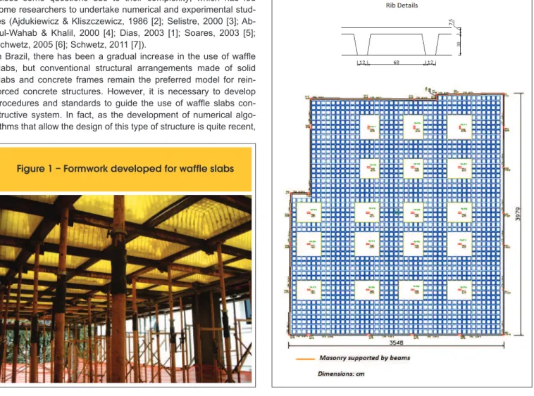
Figure 1 – Formwork developed for waffle slabs
Figure 2 – Position of top and bottom reinforcement
The loading adopted in the original design was the structure’s own weight of 4.8 kN/m2 with an additional dead load of 12 kN/m2, a live load of 3.0 kN/m2 and a masonry load applied directly on the edge beams. The high value of the additional dead load is due to the several layers of the base illing material of the tennis court. Only the additional dead load was used in the experimental program.
2.2 Instrumentation
The experimental program predicted measurement of strains and vertical displacements.
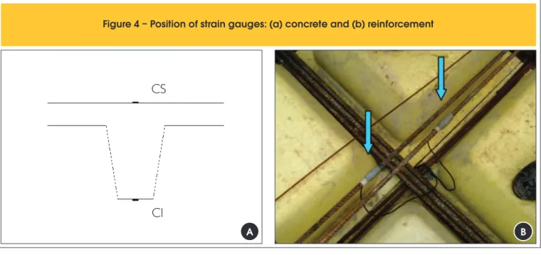
In the concrete, strain gauges were placed in four slab locations, at the top and bottom surfaces (Fig. 4a). In the reinforcement, two strain gauges were placed at each instrumented location, protect
-ed with an epoxy bas-ed resin (Fig. 4b).
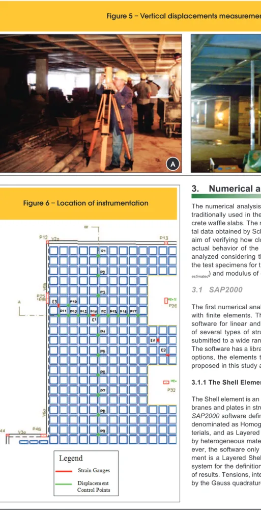
A precision optical level was used to measure the vertical displace
-ments (Fig. 5) at locations as shown in Fig. 6.
2.3 Testing
The test began 63 days after casting. The loading was to be car
-ried out in three stages and strain and vertical displacements were to be measured at the end of each loading stage. However, the load was distributed unevenly throughout the testing period. Some areas of the slab were used to store other types of material gen
-erating a non-uniform load (Fig. 7a and b). Hence, readings were made at different points in time and care was taken to register the actual load applied at each reading. The process of loading the structure lasted 87 days and readings were taken at 5 different times. Cylinder tests were also carried out to determine the modu
-lus of longitudinal elasticity of the concrete (E) and the character
-istic concrete strength (fck). The average value of the modulus of elasticity of the concrete E28 measured experimentally was equal to 28,45 GPa, and the average concrete strength obtained at 28 days was equal to 33,27 MPa, corresponding to a concrete characteris
-tic strength fck, estimated equal to 30 MPa. and to verify whether their behavior is adequately simulated by
the design methods and mathematical models widely used today. In order to achieve this aim, an experimental program was imple
-mented, measuring strains and delections in a full-scale wafle slab, designed to receive several layers of illing material neces
-sary for use as the loor of a tennis court. The experimental results were compared with results obtained from numerical analyses per
-formed using two different approaches to represent the structure (a grid matrix analysis and FEM analysis).
2. Experimental program
The loor analyzed was designed commercially by a structural en
-gineering design ofice located in the city of Porto Alegre, Brazil. It is to be used as a tennis court loor.
The formwork was built with plastic formwork developed for wafle slabs by Ulma Fôrmas e Escoramentos Ltda. This system is com
-posed by a two-way ribbed structure that serves as support for the plastic molds. The ribbed structure is supported by a set of tubular metallic braces that are easy to disassemble (Fig. 1).
The slab reinforcement was made with type CA-50. The weight of
positive reinforcement used was about 16,000 kg and the amount of negative one was around 23,000 kg.
Fig. 2shows the generic position of the steel in the ribs. Besides the top and bottom reinforcements predicted in the numerical analysis, the structural designer considered the possibility of tensile stress on the bottom of the slab topping located between the ribs and placed a welded CA-60 steel mesh on the bottom part of the top slab.
2.1 Geometry and loading
The geometry of the wafle slab loor is shown in Fig. 3. The de
-signer used semi-inverted edge beams to increase stiffness in order to prevent excessive deformation. Around the internal col
-umns, a 37.5 cm solid slab was used due to punching shear and high bending moments.
Figure 4 – Position of strain gauges: (a) concrete and (b) reinforcement
CS
CI
3. Numerical analysis
The numerical analysis was done with two computer programs traditionally used in the design and analysis of reinforced con
-crete wafle slabs. The results were compared to the experimen
-tal data obtained by Schwetz [7] in the actual structure, with the aim of verifying how close the mathematical models are to the actual behavior of the slab. The tested slab was numerically analyzed considering the values obtained experimentally from the test specimens for the parameters compressive strength (fck, estimated) and modulus of elasticity (E28).
3.1 SAP2000
The irst numerical analysis was done using SAP2000 software with inite elements. The SAP2000 is a structural engineering software for linear and nonlinear static and dynamic analyses of several types of structures, simulating their behavior when submitted to a wide range of demands [8].
The software has a library of inite elements. Among the existing options, the elements that were used in the numerical models proposed in this study are described below.
3.1.1 The Shell Element
The Shell element is an area element used to model shells, mem
-branes and plates in structures in two and three dimensions. The SAP2000 software deines two types of Shell element. They are denominated as Homogeneous Shell, used for homogenous ma
-terials, and as Layered Shell, used when the element is formed by heterogeneous materials or by more than one material. How
-ever, the software only allows nonlinear analyses when the ele
-ment is a Layered Shell. Each ele-ment has its local coordinate system for the deinition of material properties, loads and output
Figure 5 – Vertical displacements measurement
A
B
3.1.2 The Frame Element
The Frame Element is a tridimensional element with six de
-grees of freedom per node: three de-grees of freedom for translation and three degrees of freedom for rotation. It is used for two or three dimensional modeling of frames, trusses and grids.
The formulation of the Frame element includes the determina
-tion of biaxial bending, torsion, axial and shear stress, through the integration of the tensions along the section. Those stresses
are determined at the ends of each element and at points along the element chosen by the user.
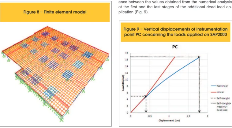
In the FE model of the wafle slab under study, which is shown in Fig. 8, the top slab, the ribs, the edge beams and the solid slab regions were modeled using shell elements, totaling approxi
-mately 23,000 elements, and the columns were modeled with frame elements. A nonlinear analysis of the structure was car
-ried out, applying three types of loads in the following sequence: self-weight, a masonry load applied directly on the edge beams and the additional dead load. The numerical results correspond
-ing to the experimental load were considered as be-ing the differ
-ence between the values obtained from the numerical analysis at the irst and the last stages of the additional dead load ap
-plication (Fig. 9).
Figure 7 – (a) Unevenly distribution of the load and (b) Slab totally loaded
A
B
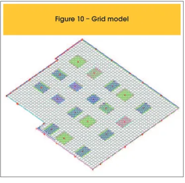
3.2 TQS software
TQS is a software developed by TQS Informática Ltda. for
rein-forced concrete structural design using the matrix analysis method for grids. This system, formed by a set of modules, creates a da
-tabase on the entire construction, grouping geometries and loads, managing the structural analysis, the transference and calculation of stresses and the detailing of all the elements that constitute the structure [9].
In the case of wafle slabs, the TQS software allows both linear and non-linear grid analysis. In linear analysis, the reinforcement is not considered in the determination of the cross sections stiff
-ness. Nonlinear analysis calculates the vertical displacements considering the reinforcement used and the physical non-linearity of concrete due to cracking, based on the recommendations of the Brazilian Concrete Code (ABNT, 2004[10]).
This software allows the structural designer to enter user deined values when determining stresses and detailing the reinforcement. In the speciic case of wafle slabs, the most relevant choices are related to the structure´s lexibility. The user may change the tor
-sional and/or lexural inertia of the bars, as well as adjust the stiff
-ness of the connections between beams and columns.
In this investigation, however, no reduction on torsional or lexural stiffness was used for the ribs or edge-beams. Additionally, the connections between ribs and beams and/or beams and columns were fully considered. This decision was made based on a para
-metric analysis, performed in a rectangular wafle slab, where the stiffness of the elements were varied and the results were com
-pared to the ones obtained using the inite element program[7]. Given the necessary input data, the software automatically gen
-erates a numerical model of the slab, such as the one shown in Fig. 10. A nonlinear analysis of the structure was also carried out. However, in the case of nonlinear analysis, this computational pro
-Figure 10 – Grid model
gram considers only the sum of all loads applied on the structure, including its self-weight. This load can, however, be divided into a number of stages to be deined by the user. Hence, in this study, the results originated only from the consideration of the additional dead load were obtained through the difference between two dif
-ferent analyses: one applying the sum of self-weight load, addition
-al dead load and masonry applied straight on beams and the other applying only the self-weight and the masonry load on the beams.
4. Analysis of the results
This study presents the results obtained in the numerical analyses and those measured experimentally regarding the additional dead load applied as indicated in Fig. 11. Slab delections and distribu
-tion of bending moments are compared using numerical and ex
-perimental results obtained along slab lines indicated as Line A and Line B as shown in Fig. 6.
4.1 Vertical displacements
Fig. 12 and 13 present delection along slab lines A and B obtained with the nonlinear analyses of the structure as well as the values obtained experimentally.
A similar behavior is veriied between numerical results of the two
models and the experimentally measured data, showing that both numerical design strategies are fairly able to represent actual waf
-le slab deformed behavior.
4.2 Bending moments
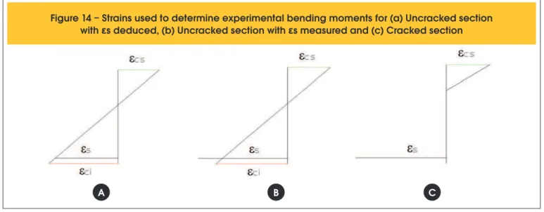
In order to compare the numerical results with the ones obtained experimentally, the measured strains had to be transformed into bending moment estimates, considering the equilibrium of internal forces in the instrumented cross-sections [11].
Three values of bending moments were determined for each sec
-tion, as shown in Fig. 14:
n Experimental uncracked section with calculated ε
s: Bending
moment is calculated considering the uncracked cross-section, with the reinforcement strain inferred from a strain gradient de
-ined from the experimental strain values measured;
n Experimental uncracked section with measured ε
s: Bending
moment is calculated considering the uncracked cross-section, but takes into account the measured reinforcement strain. This estimate of the bending moment cracking onset concerns con
-crete contribution between cracks (tension stiffening effect);
n Experimental cracked section: Bending moment is cal
-culated considering a cracked section with measured rein
-forcement strain.
Figure 12 – TQS, SAP and experimental:
deflections along line a shown in Fig. 6
Figure 13 – TQS, SAP and experimental:
deflections along line B shown in Fig. 6
Figure 14 – Strains used to determine experimental bending moments for (a) Uncracked section
with
ε
s deduced, (b) Uncracked section with
ε
s measured and (c) Cracked section
Fig. 15 shows the distribution of bending moments obtained using both numerical models, compared to the estimates of bending mo
-ments derived from the experimental data obtained at location E1. Both numerical models present a similar shape, indicating maxi
-mum positive bending in the loading area and maxi-mum negative moment in the solid slab region.
At location E1, the bending moment obtained experimentally using uncracked section with measured εs close to the values predicted by the numerical models, indicating a possible beginning of crack
-ing around this section.
Both models indicate a negative moment between the ribs and the edge beams. The value indicated by the model in FE is, higher. This difference is probably due to the fact that this model considers the top slab as a continuous plate, generating greater clamping ef
-fect on the edge beam, when compared with the grid model. Moreover, the FE model presents peaks of negative moments that are much more pronounced in the solid slab regions. This divergence may be associated to the different modeling of the solid slab regions in the soft
-wares. At these locations, unfortunately no experimental data was col
-lected, which could allow for a better assessment of the most adequate modeling for those connections and the inluence of the solid slabs.
5. Conclusions
This study presented a comparative analysis between numerical and experimental results obtained for a reinforced concrete waf
-le slab designed to serve as a loor for tennis courts. The results indicate that, with the two numerical methods used, grid matrix analysis and inite elements, there are still issues that require fur
-ther studies. The results also show the importance of undertaking experimental studies with the aim of verifying and adjusting the numerical models, particularly when new elements are adopted. The main conclusions are:
1. The results of the numerical analysis of the wafle slab system,
obtained through the grid analogy, represented here by the TQS software, show that modeling by this method is very effec
-tive, as long as the actual values for the moment of inertia are used with no reduction in the ribs, slab and beams, and rigid connections between the structural elements.
2. The inite element model, conceived in the SAP2000 software,
proved to be equally adequate. However, when compared with the simplicity of an analogy to grids, the FE model proves to be very
laborious, and dificult to use in the daily routine of design irms.
3. The grid analogy results in negative moments both in the
slab-edge beam connection and in the solid slab regions lower than those indicated by the inite element model. This difference in results may be related to the different modeling adopted by each computer program. Therefore, it is important the collection of experimental data that help deine which of the models best represent this particular aspect of the behavior of a wafle slab.
6. Aknowledgements
The authors would like to thank CNPq (the Brazilian Research Council) and the companies Projetak - Tavares Eng. Associados S/C Ltda and Construtora Tedesco for the support they have given to this project.
7. References
[01] DIAS, R. H. Análise Numérica de Pavimentos de Edifícios em Lajes Nervuradas. Dissertação (Mestrado em Engenharia) – Escola de Engenharia de São Carlos, Universidade de São Paulo (USP), São Carlos, 2003. [02] AJDUKIEWICZ, A.; STAROLSKI, W. Reinforced-
concrete slab-column stuctures. New York: Elsevier Science Publishers, 1986.
[03] SELISTRE, S. L.C. Análise Teórico-Experimental de uma Laje Nervurada de Microconcreto Submetida a um Carregamento Uniformemente Distribuído. Dissertação (Mestrado em Engenharia) – Curso de Pós-Graduação em Engenharia Civil, Universidade Federal do Rio Grande do Sul, Porto Alegre, 2000. [04] ABDUL-WAHAB, H. M. S.; KHALIL, M. H. Rigidity and
Strength of Orthotropic Reinforced Concrete Wafle Slabs. Journal of Structural Engineering, v. 126, n. 2,
Feb., p. 219-227, 2000.
[05] SOARES, Y.V. Análise Experimental de Lajes Cogumelo Nervuradas de Concreto Armado com Pilares Metálicos. Dissertação (Mestrado em Engenharia) – Curso de Pós-Graduação em Engenharia Civil, UFSC, Florianópolis, 2003.
[06] SCHWETZ, P. F. Análise teórico-experimental de uma laje nervurada modelo reduzido sujeita a um
carregamento linear. Dissertação (Mestrado em Engenharia) – Curso de Pós-Graduação em Engenharia Civil, UFRGS, Porto Alegre, 2005. [07] SCHWETZ, P.F. Análise Numérico-Experimental de
Lajes Nervuradas Sujeitas a Cargas Estáticas de Serviço. Tese (Doutorado em Engenharia) – Escola de Engenharia, Universidade Federal do Rio Grande do Sul, Porto Alegre, 2011.
[08] COMPUTERS AND STRUCTURES, INC. CSI Analysis Reference Manual. Berkeley: University Avenue, 2010. [09] TQS Informática Ltda. (a) . Sistemas Computacionais
– Engenharia Estrutural: CAD/Formas. São Paulo, s.d. várias paginações.
[10] ASSOCIAÇÃO BRASILEIRA DE NORMAS TÉCNICAS. NBR 6118:2003 : projeto e execução de obras de